Echo PB-460LN User manual

X753002784
04/13
X7531121804
Power Blower
Operator's Manual
MODEL PB-460LN
WARNING
Users of this equipment risk injury to themselves and others if the unit is used im-
properly and/or safety precautions are not followed. ECHO provides an operator’s
manual. It must be read and understood for proper and safe operation. Failure to
do so could result in serious injury.

2
TABLE OF CONTENTS
Introduction................................................................2
- The Operator's Manual .......................................2
Safety .........................................................................3
- Manual Safety Symbols and Important
Information.........................................................3
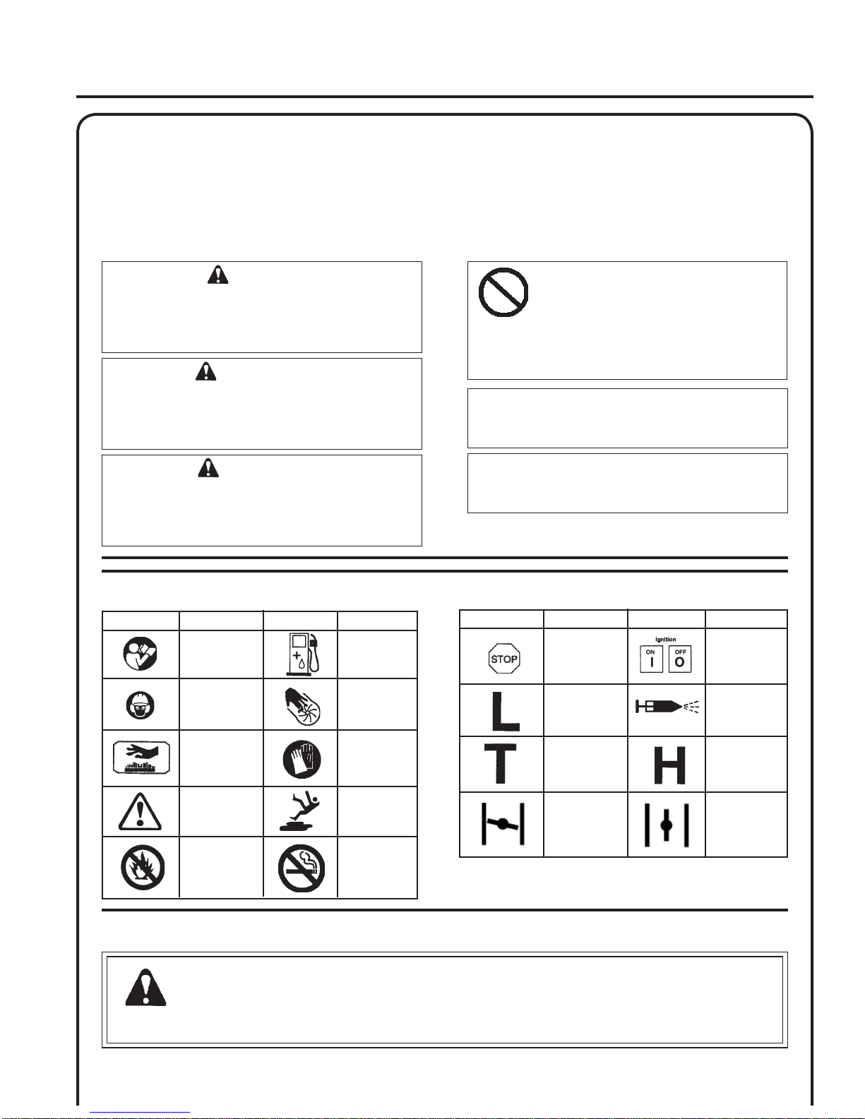
- International Symbols.........................................3
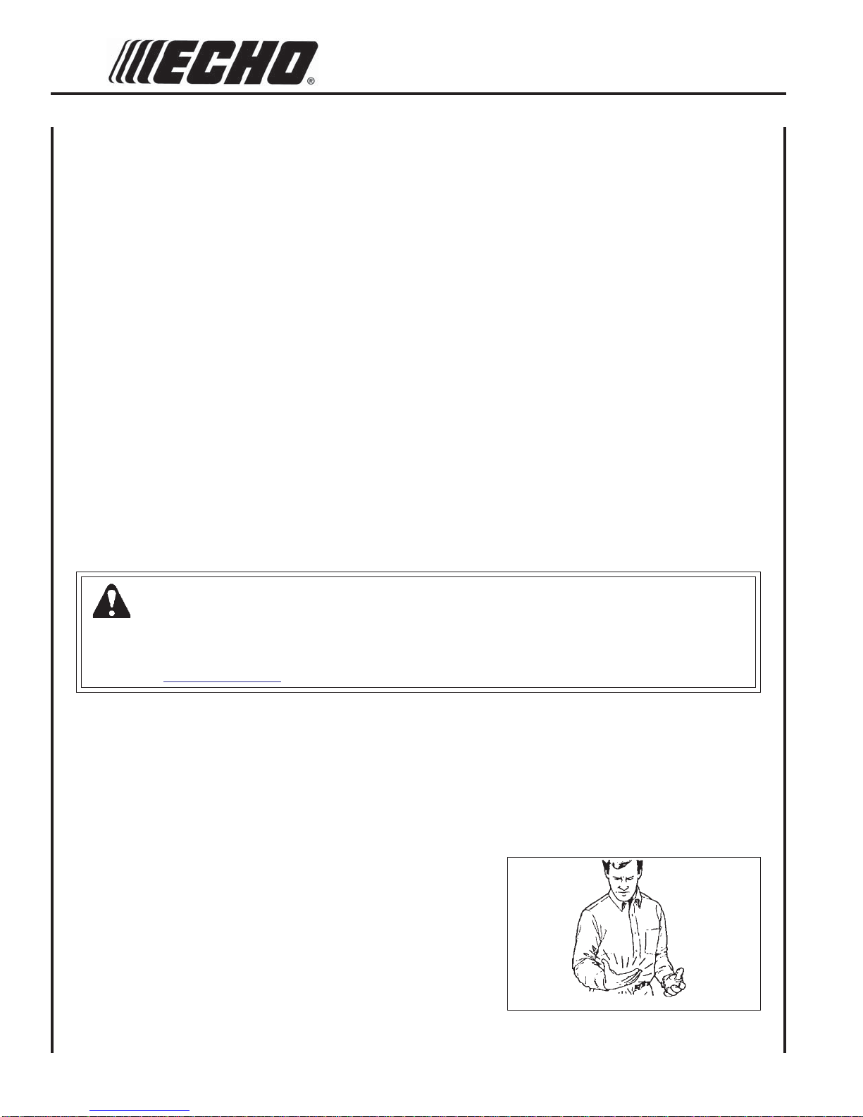
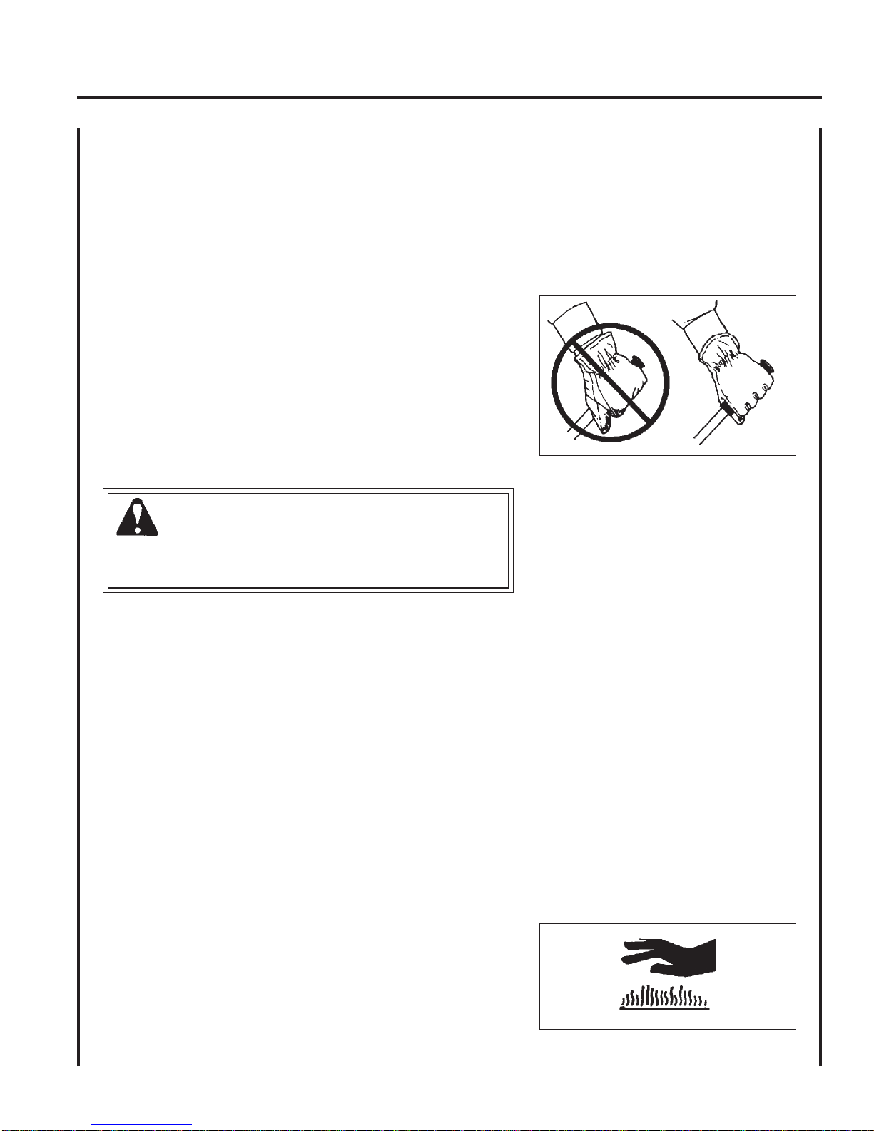
- Personal Condition and Safety Equipment.........3
- Equipment...........................................................6
Emission Control .......................................................6
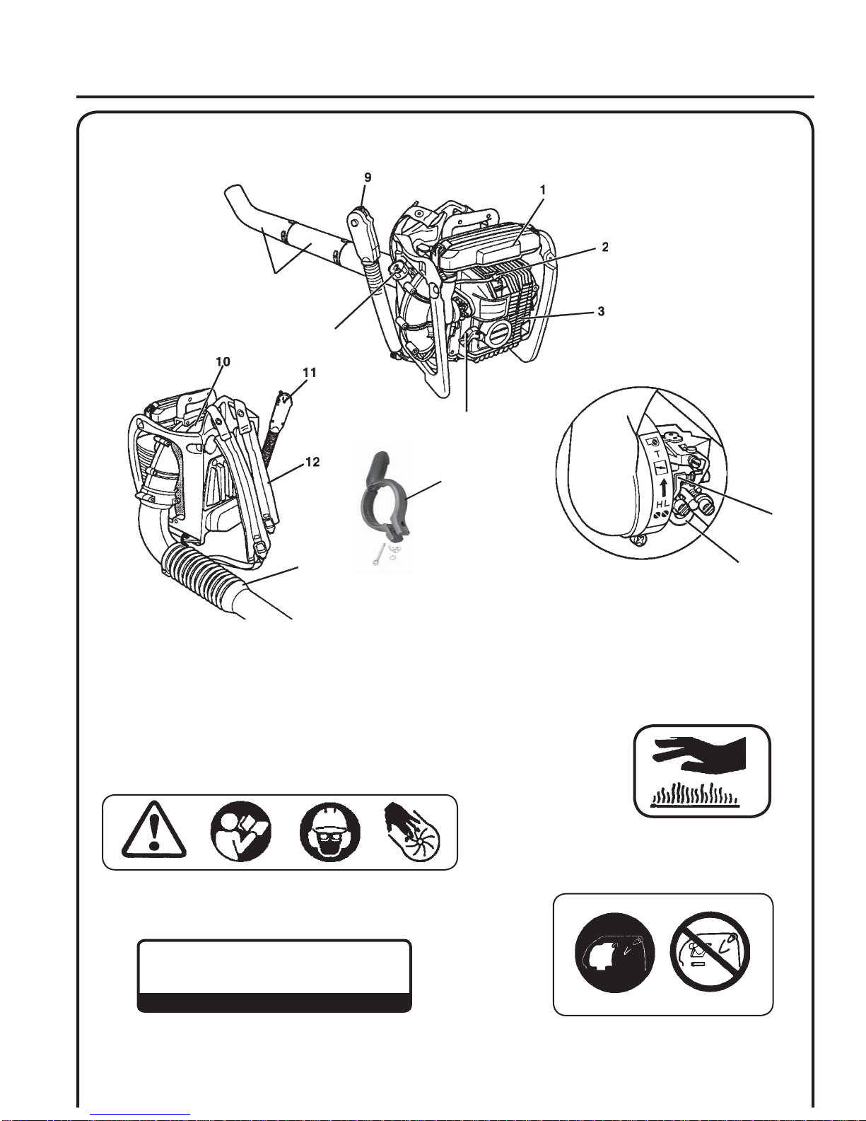
Description.................................................................7
Contents .....................................................................8
Assembly....................................................................9
- Install Blower Pipes / Stick Handle....................9
Operation..................................................................10
- Fuel...................................................................10
- Starting Cold Engine.........................................12
- Starting Warm Engine.......................................13
- Stopping Engine................................................13
- Operating Blower..............................................14
Maintenance.............................................................15
- Skill Levels.......................................................15
- Maintenance Intervals.......................................15
- Air filter ............................................................16
- Fuel Filter..........................................................17
- Spark Plug.........................................................17
- Cooling System.................................................18
- Exhaust System.................................................18
- Carburetor Adjustment......................................21
- High Altitude Operation................................21
Troubleshooting.......................................................23
Storage .....................................................................24
Specifications...........................................................25
Warranty Statements................................................26
Servicing Information..............................................28
- Parts ..................................................................28
- Service ..............................................................28
- Customer Assistance.........................................28
- Warranty Card...................................................28
- Additional or Replacement Manuals................28
- Manual Ordering Instructions...........................28
Specifications, descriptions and illustrative material in this
literature are as accurate as known at the time of publica-
tion, but are subject to change without notice. Illustrations
may include optional equipment and accessories, and may
not include all standard equipment.
Copyright© 2013 By Echo, Incorporated
All Rights Reserved.
INTRODUCTION
Welcome to the ECHO family. is ECHO product was designed and manufactured to provide long life and on-the-
job-dependability. Read and understand this manual. You will nd it easy to use and full of helpful operations tips and
SAFETY messages.
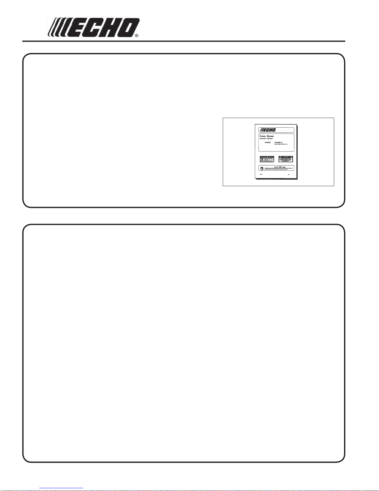
THE OPERATOR'SMANUAL
Keep it in a safe place for future reference. Contains specications and
information for safety, operation, maintenance, storage, and assembly
specic to this product.

3
POWER BLOWER
OPERATOR'SMANUAL
SAFETY
MANUAL SAFETY SYMBOLS AND IMPORTANT INFORMATION
Throughout this manual and on the product itself, you will find safety alerts and helpful, informational messages pre-
ceded by symbols or key words. The following is an explanation of those symbols and key words and what they mean to
you.
INTERNATIONAL SYMBOLS
Symbol
description/application Symbol form/shape Symbol
description/application
Symbol form/shape
Read and understand
Operator's Manual. Fuel and oil mixture
Symbol
description/application Symbol form/shape Symbol
description/application
Symbol form/shape
Hot
Surface Carburetor adjustment
- Idle speed Carburetor adjustment
- High speed mixture
Wear eyes, ears and
head protection
Emergency stop
Finger Severing Carburetoradjustment
- Low speed mixture
Safety/Alert
Wear hand
protection. Use
two handed.
DO NOT smoke
near fuel.
DO NOT allow
flames or sparks
near fuel.
Wear slip resis-
tant foot wear.
Ignition
ON/OFF
Primer
bulb
Choke Control
"Cold Start"
Position
(Choke Closed)
Choke Control
"Run"
Position
(Choke Open)
WARNING
The safety alert symbol accompanied by the word
“WARNING” calls attention to an act or condi-
tion which CAN lead to serious personal injury or
death if not avoided.
CIRCLE AND SLASH SYMBOL
This symbol means the specific action
shown is prohibited. Ignoring these prohi-
bitions can result in serious or fatal injury.
CAUTION
The safety alert symbol accompanied by the word
“CAUTION” calls attention to an act or condition
which may lead to minor or moderate personal
injury if not avoided.
NOTE
This enclosed message provides tips for use, care and
maintenance of the unit.
IMPORTANT
The enclosed message provides information neces-
sary for the protection of the unit.
DANGER
The safety alert symbol accompanied by the word
“DANGER” calls attention to an act or condition
which WILLlead to serious personal injury or
death if not avoided.
PERSONAL CONDITION AND SAFETY EQUIPMENT
WARNING
Users of this product risk injury to themselves and others if the unit is used improperly and/or safety precautions are
not followed. Proper clothing and safety gear must be worn when operating unit.

4
Vibration and Cold
It is believed that a condition called Raynaud’s Phenomenon, which affects the fingers of certain individuals, may be
brought about by exposure to vibration and cold. Exposure to vibration and cold may cause tingling and burning sen-
sations, followed by loss of color and numbness in the fingers. The following precautions are strongly recommended,
because the minimum exposure, which might trigger the ailment, is unknown.
• Keep your body warm, especially the head, neck, feet, ankles,
hands, and wrists.
• Maintain good blood circulation by performing vigorous arm
exercises during frequent work breaks, and also by not smoking.
• Limit the hours of operation. Try to fill each day with jobs where
operating the unit or other hand-held power equipment is not
required.
• If you experience discomfort, redness, and swelling of the fingers
followed by whitening and loss of feeling, consult your physician
before further exposing yourself to cold and vibration.
Physical Condition
Your judgment and physical dexterity may not be good:
• if you are tired or sick,
• if you are taking medication,
• if you have taken alcohol or drugs.
Operate unit only if you are physically and mentally well.
Eye Protection
Wear eye protection that meets ANSI Z87.1 or CE require-
ments whenever you operate the unit.
Hand Protection
Wear no-slip, heavy-duty work gloves to improve your grip
on the blower handle. Gloves also reduce the transmission of
machine vibration to your hands.
Breathing Protection
Wear a facemask to protect against dust.
Hearing Protection
ECHO recommends wearing hearing protection whenever
unit is used.
Proper Clothing
Wear snug fitting, durable clothing;
• Pants should have long legs, shirts with long sleeves.
• DO NOT WEAR SHORTS,
• DO NOT WEAR TIES, SCARVES, JEWELRY,
or clothing with loose or hanging items that could
become entangled in moving parts or surrounding
growth..
Wear sturdy work shoes with nonskid soles;
• DO NOT WEAR OPEN TOED SHOES,
• DO NOT OPERATE UNIT BAREFOOTED.
Wear no-slip, heavy duty work gloves.
Keep long hair away from engine and air intake. Retain
hair with cap or net.
Hot Humid Weather
Heavy protective clothing can increase operator fatigue
which may lead to heat stroke. Schedule heavy work for
early morning or late afternoon hours when temperatures
are cooler.
WARNING
The ignition components of this machine generate an electromagnetic field during operation which may interfere
with some pacemakers. To reduce the risk of serious or fatal injury, persons with pacemakers should consult with
their physician and the pacemaker manufacturer before operating this machine. In the absence of such informa-
tion, ECHO does not recommend the use of ECHO products by anyone who has a pacemaker.

5
POWER BLOWER
OPERATOR'SMANUAL
DANGER
Do not operate this product indoors or in inadequately ventilated
areas. Engine exhaust contains poisonous emissions and can cause
serious injury or death.
Read the Manuals
• Provide all users of this equipment with the Operator’s Manual
for instructions on Safe Operation.
Clear the Work Area
• Spectators and fellow workers must be warned, and children and
animals prevented from coming nearer than 15 m (50 ft.) while
the unit is in use.
• Take wind conditions into account: avoid open doors and win-
dows.
• Do not point blower at people or animals.
Keep a Firm Grip
• Hold the front and rear handles with both hands, with thumbs
and fingers encircling the handles.
Keep a Solid Stance
• Maintain footing and balance at all times. Do not stand on slip-
pery, uneven or unstable surfaces. Do not work in odd positions
or on ladders. Do not over reach.
Avoid Hot Surfaces
• Keep exhaust area clear of flammable debris.Avoid contact dur-
ing and immediately after operation.
Repetitive Stress Injuries
It is believed that overusing the muscles and tendons of the fingers, hands, arms, and shoulders may cause soreness,
swelling, numbness, weakness, and extreme pain in those areas. Certain repetitive hand activities may put you at a high
risk for developing a Repetitive Stress Injury (RSI). An extreme RSI condition is Carpal Tunnel Syndrome (CTS), which
could occur when your wrist swells and squeezes a vital nerve that runs through the area.
Some believe that prolonged exposure to vibration may contribute to CTS. CTS can cause severe pain for months or
even years.
To reduce the risk of RSI/CTS, do the following:
• Avoid using your wrist in a bent, extended, or twisted position.
Instead try to maintain a straight wrist position. Also, when
grasping, use your whole hand, not just the thumb and index
finger.
• Take periodic breaks to minimize repetition and rest your hands.
• Reduce the speed and force with which you do the repetitive
movement.
• Do exercises to strengthen the hand and arm muscles.
• Immediately stop using all power equipment and consult a doc-
tor if you feel tingling, numbness, or pain in the fingers, hands,
wrists, or arms. The sooner RSI/CTS is diagnosed, the more
likely permanent nerve and muscle damage can be prevented.

6
EQUIPMENT CHECK
WARNING
Use only ECHO approved attachments. Serious injury may result from the use of a non-approved attachment combi-
nation. ECHO, INC. will not be responsible for the failure of cutting devices, attachments or accessories which have
not been tested and approved by ECHO. Read and comply with all safety instructions listed in this manual and safety
manual.
• Check unit for loose/missing nuts, bolts and screws. Tighten and/or replace as needed.
• Do not use blower if any part is missing or damaged.
• Have repairs done only by an authorized ECHO Service dealer.
• Do not use any attachment, accessory or replacement part unless it is recommended in this Operator's Manual.
WARNING
Check fuel system for leaks due to fuel tank damage, especially if the unit is dropped. If damage or leaks are found,
do not use unit, otherwise serious personal injury or property damage may occur. Have unit repaired by an authorized
servicing dealer before using.
WARNING
Moving parts can amputate fingers or cause severe injuries. Keep hands, clothing and loose objects away from all
openings.
• ALWAYS stop engine, disconnect spark plug, and make sure all moving parts have come to a complete stop
before removing obstructions, clearing debris, or servicing unit.
• DO NOT start or operate unit unless all guards and protective covers are properly assembled to unit.
• NEVER reach into any opening while the engine is running. Moving parts may not be visible through openings.
An Emission Control Label is located on the engine.
(This is an EXAMPLE ONLY, information on label varies
by engine FAMILY).
EMISSION CONTROL (EXHAUST &EVAPORATIVE)
EPA 2010 and Later and/or C.A.R.B. TIER III
PRODUCT EMISSION DURABILITY (EMISSION COMPLIANCE PERIOD)
e 50 or 300 hour emission compliance period is the time span selected by the manufacturer certifying the engine
emissions output meets applicable emissions regulations, provided that approved maintenance procedures are fol-
lowed as listed in the Maintenance Section of this manual.
e emission control system for the engine is EM (engine
modication) and, if the second to last character of the Engine
Family on the Emission Control Information label (sample
below) is “C”, “K”, or “T”, the emission control system is EM
and TWC (3-way catalyst). e fuel tank/fuel line emission
control system is EVAP (evaporative emissions). Evaporative
emissions for California models are only applicable to fuel
tanks.

7
POWER BLOWER
OPERATOR'SMANUAL
4
5
6
7
8
13
DESCRIPTION
14
65 Category I
dB(A)
Measured at 50 ft. (15m) per ANSI B175.2
Spark Plug Cover Label
Hot Decal (near muffler)
General Warning Decal (located on top of blower)
Sound Label (located on blower housing)
Locate these safety decals on your unit. Make sure the decals are
legible and that you understand and follow the instructions on them.
If a decal cannot be read, a new one can be ordered from your ECHO
dealer. See PARTS ORDERING instructions for specific information.

8
1. AIR CLEANER - Contains replaceable air filter element.
2. SPARK PLUG - Provides spark to ignite fuel mixture. Spark plug is located under the cover on LN models.
3. SPARK ARRESTOR MUFFLER OR SPARK ARRESTOR MUFFLER WITH CATALYST - The muffler or
catalytic muffler controls exhaust noise and emission. The spark arrestor screen prevents hot, glowing particles of
carbon from leaving the muffler. Keep exhaust area clear of flammable debris.
4. RECOIL STARTER HANDLE - Pull recoil handle slowly until starter engages, then quickly and firmly. When
engine starts, return handle slowly. DO NOT let handle snap back or damage to unit will occur.
5. PURGE BULB - Pumping purge bulb before starting engine draws fresh fuel from the fuel tank, purging air from
the carburetor. Pump purge bulb until fuel is visible and flows freely in the clear fuel tank return line. Pump purge
bulb an additional 4 or 5 times.
6. CHOKE - Move lever up to Cold Start ( ) starting position and for emergency stopping. Move lever down to
Run position ( ).
7. FUELTANK CAP - Covers and seals fuel tank.
8. BLOWER PIPES - Twist lock design.
9. THROTTLE POSITION LEVER/STOP SWITCH - Combination stop switch and variable speed throttle lever.
When the lever is moved all the way forward the blower is at Wide Open Throttle (W.O.T.). When the lever is
moved rearward to detent, the blower is at idle. When the lever is moved rearward past the idle detent the blower
will stop.
10. SAFETY DECAL - Lists important safety precautions.
11. THROTTLE HANDLE - Rotates downward for throttle control access. Spring loaded for flexible operation.
12. SHOULDER HARNESS - Supports unit on operator's back. Pull down on loose ends of straps to position unit for
comfortable operation. Loosen straps to remove the unit.
13. FLEXIBLE PIPE - Allows for full range of movement.
14. STICK HANDLE - Provides comfortable grip for directing air flow.
CONTENTS
___ 1 - Power Head
___ 1 - Flex Pipe
___ 1 - Pipe with Swivel
___ 1 - Straight Pipe
___ 1 - Curved Pipe
___ 1 - Operator's Manual
___ 1 - Warranty Registration Card
___ 1 - Emission Control Warranty Statement
___ 2 - Clamps w/screws
___ 1 - Stick Handle Assembly

9
POWER BLOWER
OPERATOR'SMANUAL
ASSEMBLY
WARNING
Never perform maintenance or assembly procedures with engine
running or serious personal injury may result.
INSTALL BLOWER PIPES / STICK HANDLE
1. Assemble clamps (A) onto both ends of flexible pipe (B).
2. Assemble swivel pipe (C) into flexible pipe (B) and tighten clamp
(A).
3. Assemble flexible pipe (B) to elbow (D) on blower and tighten
clamp (A).
NOTE
A light lubricant may be used to ease assembly of flexible pipe to
blower elbow.
4. Loosen wing nut (E) completely and open stick handle clamp.
5. Align notches (F) in handle clamp with tabs (G).
6. Slide stick handle onto swivel pipe (C). Stick handle should be
angled away from operator.
7. Position stick handle (H) for comfortable operation, and tighten
wing nut (E).
8. Assemble straight pipe (I) to swivel pipe (C), turning straight pipe
clockwise to lock in place.
9. Assemble curved pipe (J) to straight pipe (I) turning curved pipe
(J) clockwise to lock in place.
I
J
C
C
AA
B
B
D
H
E
G
F
G

10
NOTICE: Use of unmixed, improperly mixed, or fuel older than 90 days, (stale fuel), may cause hard starting, poor
performance, or severe engine damage and void the product warranty. Read and follow instructions in the Storage
section of this manual.
WARNING
Alternative fuels, such as E-15 (15% ethanol), E-85 (85% ethanol) or any fuels not meeting ECHO requirements are
NOT approved for use in ECHO 2-stroke gasoline engines. Use of alternative fuels may cause performance prob-
lems, loss of power, overheating, fuel vapor lock, and unintended machine operation, including, but not limited to,
improper clutch engagement. Alternative fuels may also cause premature deterioration of fuel lines, gaskets, carbu-
retors and other engine components.
Fuel Requirements
Gasoline - Use 89 Octane [R+M/2] (mid grade or higher) gasoline known to be good quality. Gasoline may contain up to
10% Ethanol (grain alcohol) or 15% MTBE (methyl tertiary-butyl ether). Gasoline containing methanol (wood alcohol)
is NOT approved.
Two Stroke Oil - A two-stroke engine oil meeting ISO-L-EGD (ISO/CD 13738) and J.A.S.O. FD Standards must be
used. Echo brand premium Power Blend X TM Universal 2-Stroke Oil meets these standards. Engine problems due to
inadequate lubrication caused by failure to use an ISO-L-EGD (ISO/CD 13738) and J.A.S.O. FD certified oil, such as
Echo premium Power Blend X TM, will void the two-stroke engine warranty.
OPERATION
WARNING
Moving parts can amputate fingers or cause severe injuries. Keep hands, clothing and loose objects away from all
openings. Always stop engine, disconnect spark plug, and make sure all moving parts have come to a complete stop
before removing obstructions, clearing debris, or servicing unit. Blower housing may contain shredder blades and
other sharp edges that can cause serious injuries if touched, even if engine is off and blades are not moving. Wear
gloves to protect hands from sharp edges and hot surfaces.
FUEL
IMPORTANT
Echo premium Power Blend X TM Universal 2-Stroke Oil may be mixed at 50:1 ratio for application in all Echo en-
gines sold in the past regardless of ratio specified in those manuals.
WARNING
Operation of this equipment may create sparks that can start res. is unit is equipped with a spark arrestor to
prevent discharge of hot particles from the engine. Metal blade use also can create sparks if the blade strikes rocks,
metal, or other hard objects. Contact local re authorities for laws or regulations regarding re prevention require-
ments.

11
POWER BLOWER
OPERATOR'SMANUAL
Handling Fuel
DANGER
Fuel is VERY flammable. Use extreme care when mixing, storing or handling or serious personal injury may result.
• Use an approved fuel container.
• DO NOT smoke near fuel.
• DO NOT allow flames or sparks near fuel.
• Fuel tanks/cans may be under pressure. Always loosen fuel caps slowly allowing pressure to equalize.
• NEVER refuel a unit when the engine is HOT or RUNNING!
• DO NOT fill fuel tanks indoors. ALWAYS fill fuel tanks outdoors over bare ground.
• DO NOT overfill fuel tank. Wipe up spills immediately.
• Securely tighten fuel tank cap and close fuel container after refueling.
• Inspect for fuel leakage. If fuel leakage is found, do not start or operate unit until leakage is repaired.
• Move at least 3m (10 ft.) from refueling location before starting the engine.
Mixing Instructions
1. Fill an approved fuel container with half of the required amount
of gasoline.
2. Add the proper amount of 2-stroke oil to gasoline.
3. Close container and shake to mix oil with gasoline.
4. Add remaining gasoline, close fuel container, and remix.
IMPORTANT
Spilled fuel is a leading cause of hydrocarbon emissions. Some
states may require the use of automatic fuel shut-off containers
to reduce fuel spillage.
After use
• DO NOT store a unit with fuel in its tank. Leaks can occur. Return
unused fuel to an approved fuel storage container.
Storage - Fuel storage laws vary by locality. Contact your local gov-
ernment for the laws affecting your area.As a precaution, store fuel in
an approved, airtight container. Store in a well-ventilated, unoccupied
building, away from sparks and flames.
IMPORTANT
Stored fuel ages. Do not mix more fuel than you expect to use in
thirty (30) days, ninety (90) days when a fuel stabilizer is added.
IMPORTANT
Stored two-stroke fuel may separate. ALWAYS shake fuel con-
tainer thoroughly before each use.
Fuel to Oil Mix - 50:1 Ratio
U.S. METRIC
Gas Oil Gas Oil
Gallons FL. oz. Liter cc.
1 2.6 4 80
2 5.2 8 160
5 13 20 400

12
STARTING COLD ENGINE
• Recoil starter: Use short pulls - only 1/2-2/3 of rope length for
starting. Do not allow the rope to snap back in. Always hold the
unit firmly.
• Rotate throttle handle downward to a comfortable operating posi-
tion.
1. Throttle Lever
Move throttle lever (A) to Wide Open Throttle position.
2. Choke
Move choke (B) up to Cold Start position ( ).
3. Purge Bulb
Pump purge bulb (C) until fuel is visible and flows freely in the
clear fuel tank return line. Pump bulb an additional 4 or 5 times.
4. Recoil Starter
Pull recoil starter handle (D) until engine fires (5 pulls).
5. Choke
After engine fires (or 5 pulls), move choke lever to Run ( )
position. Keep throttle lever in wide open throttle position, and
pull recoil starter handle until engine starts and runs.
NOTE
If engine does not start with choke in “Run” position after 5 pulls,
move choke to “Cold Start” ( ) position, and repeat steps 4 & 5.
6. Throttle Lever
Move throttle lever to IDLE position, and allow engine to warm
up at idle for several minutes.
7. Throttle Lever
After engine warm-up, move throttle lever gradually to increase
engine RPM to desired operating speed.starting warm engine
A
D
B
C

13
POWER BLOWER
OPERATOR'SMANUAL
STARTING WARM ENGINE
1. Throttle Lever
Move throttle lever (A) to IDLE DETENT position.
2. Purge Bulb
Pump purge bulb (C) until fuel is visible and flows freely in the
clear fuel tank return line. Pump bulb an additional 4 or 5 times.
3. Recoil Starter
Pull recoil starter handle (D) and engine should start. Do not use
choke (B).
NOTE
If engine does not start after 5 pulls, use cold start procedures.
STOPPING ENGINE
1. Throttle Lever
Move throttle lever (A) to idle detent position and allow engine to
return to idle before shutting off engine.
2. Move throttle lever (A) to "O" (Stop) position.
WARNING
If engine does not stop when stop switch is moved to STOP posi-
tion, close choke - COLD START position - to stall engine. Have
your ECHO dealer repair stop switch before using blower again.
A
A
C
D

14
OPERATING BLOWER
WARNING
Engine exhaust IS HOT, and contains Carbon Monoxide (CO), a
poison gas. Breathing CO can cause unconsciousness, serious in-
jury, or death. Exhaust can cause serious burns. ALWAYS position
unit so that exhaust is directed away from your face and body.
WARNING
Always wear safety glasses, hearing protection, a face filter mask
and take all safety precautions or serious personal injury may result.
Do not point the blower pipe in the direction of people or pets.
IMPORTANT
Use reduced speed only when performing light-duty tasks or to
comply with local noise regulations. Continuous low speed opera-
tion may allow fuel/oil residue to build-up on the piston and cause
rapid build-up of carbon on the spark arrestor screen, resulting in
overheating and engine damage. To reduce harmful build-up, run
engine at wide open throttle for at least 5 minutes every hour, and
inspect/clean the spark arrestor screen after approximately 40 hours
of operation.
Read the Safety Section carefully.
IMPORTANT
To avoid engine damage due to over-revving, do not block
blower pipe opening.
1. Use only during appropriate hours.
2. Make sure all blower pipes are installed.
3. Allow the engine to warm up at a fast idle for a few minutes.
4. Set engine speed with throttle (A).
5. Use lower speed to blow dry grass and leaves from walks, patios
and drives.
6. Additional speed may be necessary to clean leaves from a lawn or
flower bed.
7. Higher speed may be necessary to move gravel, dirt, snow, bottles
or cans from a driveway, street, parking lot or stadium.
NOTE
Never use a higher speed setting than necessary to perform a task.
Remember, the higher the engine speed, the louder the blower
noise. Minimize dust by using blower at lower speeds and by
dampening material with water/mist when necessary. Keep debris
on your property.
Be Smart - be a good neighbor.
A

15
POWER BLOWER
OPERATOR'SMANUAL
Your ECHO blower is designed to provide many hours of trouble free service. Regular scheduled maintenance will help
your blower achieve that goal. If you are unsure or are not equipped with the necessary tools, you may want to take your
unit to an ECHO Service Dealer for maintenance. To help you decide whether you want to DO-IT-YOURSELF or have
the ECHO Dealer do it, each maintenance task has been graded. If task is not listed, see your ECHO Dealer for repairs.
SKILL LEVEL
Level 1 = Easy to do.Common tools may be required.
Level 2 = Moderate difficulty. Some specialized tools may be required.
ECHO offers REPOWERTM Maintenance Kits and Parts to make your maintenance job easier.
MAINTENANCE
WARNING
Moving parts can amputate fingers or cause severe injuries. Keep hands, clothing and loose objects away from all
openings. Always stop engine, disconnect spark plug, and make sure all moving parts have come to a complete stop
before removing obstructions, clearing debris, or servicing unit. Allow unit to cool before performing service. Wear
gloves to protect hands from sharp edges and hot surfaces.
MAINTENANCE INTERVALS
COMPONENT / SYSTEM MAINTENANCE
PROCEDURE
REQ'D
SKILL
LEVEL
DAILY OR
BEFORE USE
EVERY
REFUEL 3 MONTHS YEARLY
Air Filter Inspect/Clean 1I / C * R *
Choke Shutter Inspect/Clean 1I / C
Fuel Filter Inspect/Replace 1I * I / R *
Fuel Cap Gasket Inspect/Replace 1I * R *
Fuel System Inspect/Replace 1I (1) * I (1) *
Spark Plug Inspect/Clean/Replace 1I / C / R *
Cooling System Inspect/Clean 2I / C
Muffler Spark Arrestor Inspect/Clean/Replace 2I / C / R *
Cylinder Exhaust Port Inspect/Clean/Decarbon 2I / C
Recoil Starter Rope Inspect/Clean 1I / C *
Screws/Nuts/Bolts Inspect/Tighten/Replace 1I *
* All recommendations to replace are based on the finding of damage or wear during inspection.
MAINTENANCE PROCEDURE LETTER CODES: I = INSPECT, R = REPLACE, C = CLEAN
IMPORTANT NOTE - Time intervals shown are maximum. Actual use and your experience will determine the
frequency of required maintenance.
MAINTENANCE PROCEDURE NOTES:
(1) Low evaporative fuel tanks DO NOT require regular maintenance to maintain emission integrity.

16
AIR FILTER
Level 1.
Parts required: Tune Up Kit
NOTE
Always brush dirt and debris away from air cleaner area prior to
cleaning air filter.
1. Brush dirt off air cleaner area. Keep dirt away from engine and
air intake grid.
2. Remove air filter cover. Brush dirt from inside cover and away
from edges of air filter.
3. Check air filter seal for tight fit with air filter case.
4. Remove air filter from case. Use care to prevent dirt and debris
from falling into air filter case.
5. Inspect filter element and seal. Replace filter if any of these prob-
lems are present:
•Air filter seal does not fit tightly against case
•Air filter seal is distorted, worn, or damaged
•Air filter element has holes or other damage
•Air filter element is saturated with dirt
•Air filter element is soaked with fuel mix
6. If air filter is in good condition and can be cleaned and reused,
lightly brush debris from air filter element, or blow filter element
clean using low pressure (40 psi or less) compressed air directed
at inside of filter.
IMPORTANT
When using compressed air, always direct air stream at inside sur-
face of filter so dust and debris will be blown out of filter. Keep air
nozzle 6 - 8 inches away from filter to prevent damage to filter.
7. Install air filter in case, and replace cover.
NOTICE
Actual replacement interval for air filter depends on operating con-
ditions. Operation in dustier applications requires more frequent
cleaning and replacement. Continued operation with a damaged
or excessively dirty filter will allow dirt and debris to enter engine,
and result in poor performance, rapid engine wear, and premature
engine failure.

17
POWER BLOWER
OPERATOR'SMANUAL
FUEL FILTER
Level 1.
Parts required: Tune Up Kit
DANGER
Fuel is VERY flammable. Use extreme care when mixing, storing
or handling.
1. Use a clean rag to remove loose dirt from around fuel cap and
empty fuel tank.
2. Use the “fuel line hook” to pull the fuel line and filter from the
tank.
3. Remove the filter from the line and install the new filter.
NOTE
Federal EPA regulations require all model year 2012 and later gaso-
line powered engines produced for sale in the United States to be
equipped with a special low permeation fuel supply hose between
the carburetor and fuel tank. When servicing model year 2012 and
later equipment, only fuel supply hoses certified by EPA can be
used to replace the original equipment supply hose. Fines up to
$37,500 may be enforced for using an un-certified replacement part.
SPARK PLUG
Level 2.
Parts Required: Tune Up Kit
IMPORTANT
Use only NGK BPM-8Y spark plug (BPMR-8Y in Canada)
otherwise severe engine damage may occur.
1. Remove spark plug cover and spark plug, check for fouling, worn
and rounded center electrode.
2. Clean the plug or replace with a new one. DO NOT sand blast to
clean. Remaining sand will damage engine.
3. Adjust spark plug gap by bending outer electrode.
4. Tighten spark plug to 150-170 kgf • cm (130-150 in • lbf).
5. Install spark plug cover.
IMPORTANT
Always reinstall spark plug cover, otherwise engine cooling will
be greatly reduced, and engine failure will result.
0.65 mm
(0.026 in.)

18
COOLING SYSTEMS CLEANING
Level 2.
Parts Required: None, if you are careful.
IMPORTANT
To maintain proper engine operating temperatures, cooling air
mustpass freely through the cylinder fin area. This flow of air
carriescombustion heat away from the engine.
Overheating and engine seizure can occur when:
• Air intakes are blocked, preventing cooling air from reaching the
cylinder.
• Dust and grass build up on the outside of the cylinder. This build-
up insulates the engine and prevents the heat from leaving.
Removal of cooling passage blockages or cleaning of cooling fins is
considered “Normal Maintenance.” Any failure attributed to lack of
maintenance is not warranted.
Cleaning Grill
1. Remove accumulated debris from intake grill between backpack
frame and blower housing.
Cleaning Cylinder Fins
1. Remove spark plug cover and spark plug.
2. Remove engine cover (five screws), pull cover away from engine,
and tie temporary knot in starter rope. Clean cylinder fins to allow
cooling air to pass freely.
IMPORTANT
Always reinstall spark plug cover, otherwise engine cooling will
be greatly reduced, and engine failure will result.
INTAKE
GRILL

19
POWER BLOWER
OPERATOR'SMANUAL
EXHAUST SYSTEM
Spark Arrestor Screen
Level 2.
Parts Required: Spark arrestor screen, Gaskets (3)
IMPORTANT
Carbon deposits in muffler will cause a drop in engine output
and overheating. Spark arrestor screen must be checked periodi-
cally.
1. Remove spark plug and engine cover.
IMPORTANT
Exact placement of exhaust gaskets on muffler is critical. Care-
fully note orientation of each gasket when removing and install-
ing.
2. Remove spark arrestor cover (A), gaskets (B), (C), (D), and spark
arrestor screen (E) from muffler.
NOTE
When cleaning carbon deposits, be careful not to damage the cata-
lytic element inside muffler.
3. Clean carbon deposits from muffler components.
NOTE
The exhaust gasket outlets should be partially restricted. The gas-
kets will be properly assembled when all six (6) small round holes
are in alignment.
4. Replace screen if it is cracked, plugged, or has holes burned
through.
5. Assemble components in reverse order.
DCB
A
E

20
Exhaust Port Cleaning
Level 2.
Parts Required: As needed: Heat Shield
1. Remove engine cover. See “Cleaning Cylinder Fins” for step by
step instructions.
2. Place piston at top dead center. Remove muffler (A) gasket (B),
and heat shield (C).
3. Use a wood or plastic scraping tool to clean deposits from cylin-
der exhaust port.
IMPORTANT
Never use a metal tool to scrape carbon from the exhaust port.
Do not scratch the cylinder or piston when cleaning the exhaust
port. Do not allow carbon particles to enter the cylinder.
4. Inspect heat shield (C) and gasket (B) and replace if damaged.
5. Install heat shield (C) , gasket (B), and muffler.
6. Tighten muffler mounting bolts (or nuts) to 105-150 in•lbf
(120-170 kgf•cm).
7. Install engine cover.
8. Install spark plug and tighten spark plug to 150-170 kgf • cm
(130-150 in • lbf).
9. Attach spark plug lead.
10. Install spark plug cover.
11. Start engine, and warm to operating temperature.
12. Stop engine, and re-tighten mounting bolts (or nuts) to specifica-
tions.
A
B
C
Other manuals for PB-460LN
2
Table of contents
Other Echo Blower manuals

Echo
Echo PB-413H - PARTS CATALOG SERIAL NUMBER... Instruction Manual

Echo
Echo PB-620 User manual

Echo
Echo PB-255LN User manual

Echo
Echo PB-251 User manual

Echo
Echo PB-580 H User manual

Echo
Echo CPLB-58VVN User manual

Echo
Echo PB-265ESL Mounting instructions

Echo
Echo PB-602 User manual

Echo
Echo PB-251 User manual

Echo
Echo PB-625 User manual

Echo
Echo PB-413H - 06-06 User manual

Echo
Echo PB-200 - 12-05 User manual

Echo
Echo PB-755T User manual

Echo
Echo PB-265L User manual

Echo
Echo Power Blower PB-230LN User manual

Echo
Echo PB-260L User manual

Echo
Echo PB-2155 User manual

Echo
Echo DPB-600 User manual

Echo
Echo PB-201 - User manual

Echo
Echo Shred 'N' Vac ES-1000 User manual