Echo GT-200R - SERIAL NUMBER 07003101-07999999 User manual

Grass Trimmer
Operator'sManual
MODEL GT-200R
Serial Number 07003101 - 07999999
WARNING DANGER
Readrulesforsafeoperationandinstructionscarefully. ECHOprovidesan
Operator'sManualandaSafetyManual. Bothmustbereadandunderstoodfor
properandsafeoperation.
X770000702
11/03
X7702277302

2
INTRODUCTION
Welcome to the ECHO family. This ECHO product was designed and manufactured to provide long life and on-the-
job-dependability. Read and understand this manual and the SAFETY MANUAL you found in the same package. You
will find both easy to use and full of helpful operations tips and SAFETY messages.
TABLE OF CONTENTS
Introduction ...............................................................2
- The Operator's Manual .......................................2
- The Safety Manual .............................................2
Manual Safety Symbols and Important Information ..3
Safety .........................................................................3
- Decals .................................................................3
- InternationalSymbols .........................................4
Safety Instructions ....................................................5
- Personal Conditions and Safety Equipment .......5
- ExtendedOperation/ExtremeConditions ............5
- Equipment ...........................................................6
- SafeOperation ....................................................6
EmissionControl ........................................................7
Description ................................................................7
- Contents List ......................................................7
Specifications........................................................... 10
Assembly ................................................................. 11
- PlasticShieldInstallation.................................. 11
- Nylon Head Installation.................................... 11
- NylonLineInstallation ..................................... 12
- Front(Loop)Handle ......................................... 12
Pre-Operation ........................................................... 13
- Fuel ................................................................... 13
Operation ................................................................. 14
- StartingColdEngine ......................................... 14
- StartingWarmEngine....................................... 15
- Stopping Engine ............................................... 16
Maintenance ............................................................ 16
- SkillLevel.......................................................... 16
- Maintenance Intervals ...................................... 16
- AirFilter ............................................................ 17
- FuelFilter .......................................................... 17
- Sparkplug ......................................................... 18
- CoolingSystem................................................. 18
- ExhaustSystem................................................. 19
- Carburetor Adjustment ..................................... 20
- Lubrication........................................................ 21
Troubleshooting ...................................................... 22
Storage..................................................................... 23
ServicingInformation............................................... 24
- Parts.................................................................. 24
- Service .............................................................. 24
- ECHOConsumerProductSupport.................... 24
- Warranty Card .................................................. 24
- Additional or Replacement Manuals ................ 24
THE OPERATOR'SMANUAL
Read and understand this manual before operation. Keep it in a safe
place for future reference. It contains specifications and information for
operation, starting, stopping, maintenance, storage, and assembly
specific to this product.
THE SAFETY MANUAL
Read and understand this manual before operation. Keep it in a safe
place for future reference. It explains possible hazards involved with the
use of Grass Trimmers and Brush cutters and what measures you
should take to make their use safer.
Copyright© 2003 By Echo, Incorporated
All Rights Reserved.
Specifications, descriptions and illustrative material in this
literature are as accurate as known at the time of publication,
but are subject to change without notice. Illustrations may
include optional equipment and accessories, and may not
include all standard equipment.

GRASS TRIMMER
OPERATOR'SMANUAL 3
SAFETY
DECALS
Locate these safety decals on your unit. The complete unit illustration
found in the "DESCRIPTION" section, will help you locate them. Make
sure the decals are legible and that you understand and follow the
instructions on them. If a decal cannot be read, a new one can be
orderedfromyourECHOdealer. SeePARTSORDERINGinstructions
forspecificinformation.
MANUALSAFETY SYMBOLS AND IMPORTANT INFORMATION
Throughout this manual and on the product itself, you will find safety
alerts and helpful, informational messages preceded by symbols or key
words. The following is an explanation of those symbols and key words
and what they mean to you.
This symbol accompaniedby the words WARNING
and DANGER calls attention to an act or condition that
can lead to serious personal injury to operator and
bystanders.
The circle with the slash symbol means whatever is
shown within the circle is prohibited.
IMPORTANT The enclosed message
provides information necessary for the
protection of the unit.
NOTE This enclosed message provides
tips for use, care and maintenance of the
unit.
Esta unidad puede ser peligrosa y producir
lesiones personales graves si no se usa en
forma adecuada. Para reducir el riesgo de
lesionarse, los operadores, los ayudantes y los
espectadores deben leer y comprender el
Manual Del Operador y los Manuales De
Seguridad que se entregan escritos en español.
ADVERTENCIA PELIGRO
890228-09560
This unit can be dangerous and cause serious
injury if improperly used. To reduce injury
risk to operator, helpers and bystanders, read
and understand the Operator's and Safety
Manuals, which are provided in Spanish.
WARNING DANGER
ENGLISHTRANSLATION SPANISHDECAL
P/N 89016006361
Hot Decal (near muffler)
IMPORTANT
NOTE

4
P/N 89031744530
Shaft Decal
• This unit can be dangerous and cause serious injury if improperly
used. To reduce injury risk to operator, helpers and bystanders, read
and understand the Operator's and Safety manuals.
• Blindness can occur from objects that are thrown or ricocheted even
with shield in place. Operators, helpers and bystanders must wear
ANSI Z87.1 approved eye protection.
• Always wear hearing protection when operating unit.
• Prevent accidental contact with unit and any cutting attachment.
Maintaina15m(50ft.)radius,DANGERZONEsurroundingthe
operator. ONLY the operator, dressed in proper protective clothing
shouldbeintheDANGERZONE.
• DONOTINSTALLMETALBLADESONGT(GRASSTRIMMER)
MODELS.
• Cutting attachment does not stop immediately after releasingthrottle.
Keep hands and feet clear of blade/cutting attachment unless engine
is shut off and cutting attachment is not moving.
WARNING DANGER
WEAR HAND AND
FOOTPROTECTION
KEEP BYSTANDERS AND HELPERS
AWAY 15 M (50 FT.). DO NOT USE
BLADES. STRING
LINE ONLY
DO NOT EXCEED
10,000 RPM.
DO NOT OPERATE
WITHOUT GUARDS
AND SHIELDS IN
PLACE.
BEWARE
- THROWN,
RICOCHET
OBJECTS
SYMBOL
DESCRIPTION/APPLICATION SYMBOL FORM/
SHAPE SYMBOL
DESCRIPTION/APPLICATION
SYMBOL FORM/
SHAPE
HOT
SURFACE
CARBURETOR
ADJUSTMENT
- IDLE SPEED
CARBURETOR
ADJUSTMENT
- HIGH SPEED
MIXTURE
SYMBOL
DESCRIPTION/APPLICATION SYMBOL FORM/
SHAPE SYMBOL
DESCRIPTION/APPLICATION
SYMBOL FORM/
SHAPE
Read and understand
Operator's Manual.
WEAR EYES, EARS
AND HEAD
PROTECTION
EMERGENCY STOP
FUEL AND OIL
MIXTURE
FINGER SEVERING
CARBURETOR
ADJUSTMENT
- LOW SPEED MIXTURE
SAFETY/ALERT
DO NOT SMOKE
NEAR FUEL.
DO NOT ALLOW
FLAMES OR
SPARKS NEAR
FUEL.
WEAR SLIP
RESISTANT
FOOT WEAR.
IGNITION
ON/OFF
PRIMER
BULB
INTERNATIONALSYMBOLS
CHOKE CONTROL
"COLD START"
POSITION
(CHOKE CLOSED)
CHOKE CONTROL
"RUN"
POSITION
(CHOKEOPEN)

GRASS TRIMMER
OPERATOR'SMANUAL 5
SAFETYINSTRUCTIONS
PERSONAL CONDITION AND SAFETY EQUIPMENT
WARNING DANGER
Trimmer/Brush Cutter users risk injury to themselves and others if the trimmer/brush cutter is used improperly and or
safety precautions are not followed. Proper clothing and safety gear must be worn when operating a trimmer.
Physical Condition
Your judgment and physical dexterity may not be good:
• if you are tired or sick,
• ifyou are taking medication,
• if you have taken alcohol or drugs.
Operate unit only if you are physically and mentally well.
Eye Protection
Wear eye protection that meets ANSI Z87.1 or CE
requirements whenever you operate the trimmer.
Hand Protection
Wear no-slip, heavy duty work gloves to improve your
grip on the Trimmer/Brush Cutter handles. Gloves also
reduce the transmission of machine vibration to your
hands.
Hearing Protection
ECHOrecommendswearinghearing protectionwhenever
unit is used.
Proper Clothing
Wear snug fitting, durable clothing;
• Pants should have long legs, shirts with long sleeves.
• DONOTWEARSHORTS,
• DONOTWEARTIES,SCARVES,JEWELRY.
Wear sturdy work shoes with non-skid soles;
• DONOTWEAROPENTOEDSHOES,
• DONOTOPERATEUNITBAREFOOTED.
EXTENDED OPERATION/EXTREME CONDITIONS
Vibration and Cold --
It is believed that a condition called Raynaud’s Phenomenon, which
affects the fingers of certain individuals may be brought about by
exposure to vibration and cold. Exposure to vibration and cold may
cause tingling and burning sensations followed by loss of color and
numbness in the fingers. The following precautions are strongly
recommendedbecausetheminimumexposurewhichmighttriggerthe
ailmentisunknown.
• Keep your body warm, especially the head, neck, feet, ankles, hands
and wrists.
• Maintain good blood circulation by performing vigorous arm exer-
cises during frequent work breaks and also by not smoking.
• Limit the hours of operation. Try to fill each day with jobs where
operating the trimmer or other hand-held power equipment is not
required.
• If you experience discomfort, redness and swelling of the fingers
followed by whitening and loss of feeling, consult your physician
before further exposing yourself to cold and vibration.
Repetitive Stress Injuries --
It is believed that overusing the muscles and tendons of the fingers,
hands, arms and shoulders may cause soreness, swelling, numbness,
weakness and extreme pain in those areas. Certain repetitive hand
activities may put you at a high risk for developing a Repetitive Stress
Injury(RSI).AnextremeRSIconditionisCarpalTunnelSyndrome
(CTS), which could occur when your wrist swells and squeezes a vital
nerve that runs through the area. Some believe that prolonged exposure
to vibration may contribute to CTS. CTS can cause severe pain for
months or even years.
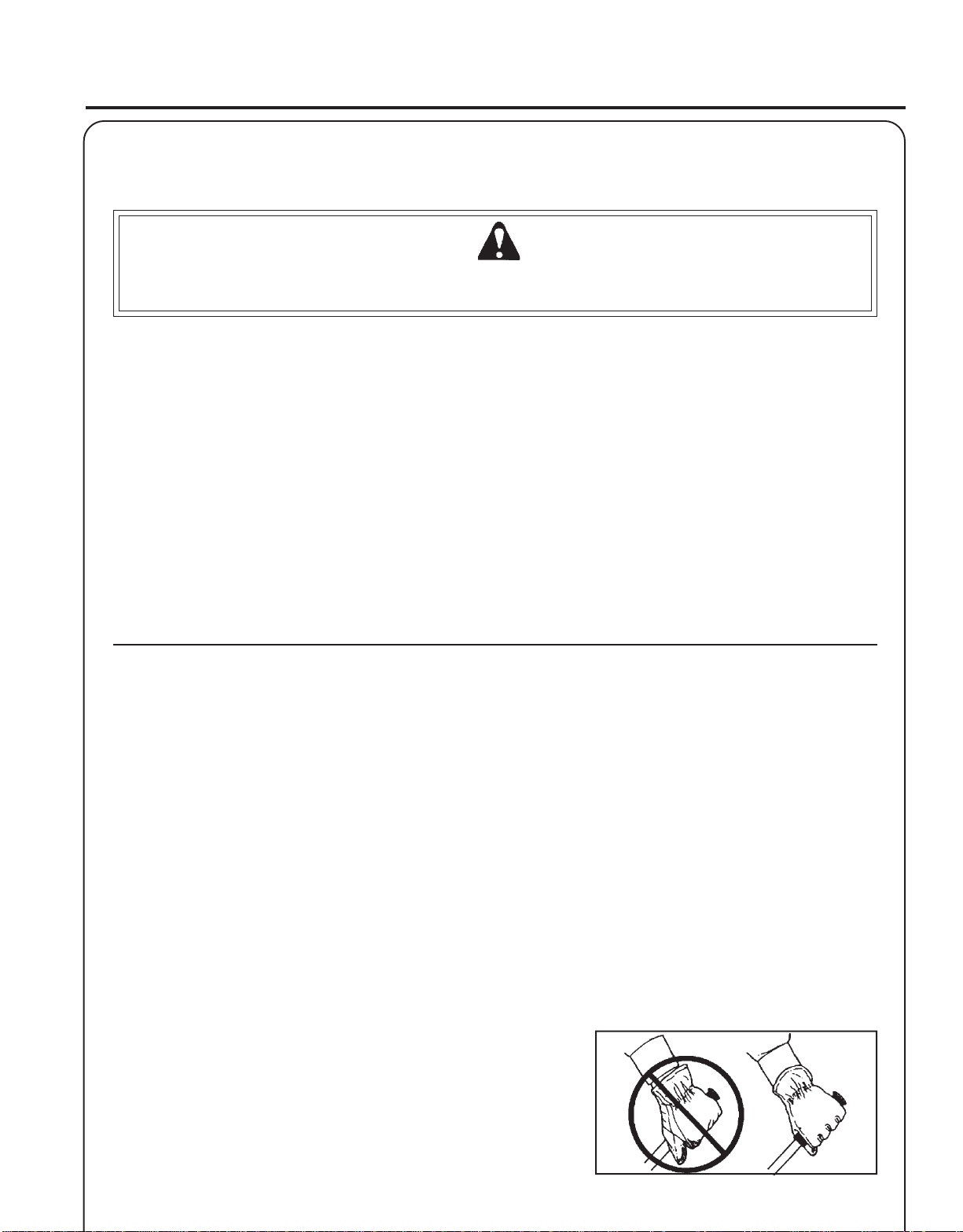
To reduce the risk of RSI/CTS, do the
following:
• Avoid using your wrist in a bent, extended
or twisted position. Instead try to maintain
a straight wrist position. Also, when
grasping, use your whole hand, not just
the thumb and index finger.
• Takeperiodicbreakstominimizerepetition
and rest your hands.
• Reduce the speed and force in which you
do the repetitive movement.
• Do exercises to strengthen the hand and
armmuscles.
• Immediately stop using all power equip-
ment and consult a doctor if you feel
tingling, numbness or pain in the fingers,
hands, wrists or arms. The sooner RSI/
CTSisdiagnosed, themorelikelyperma-
nent nerve and muscle damage can be
prevented.

6
SAFE OPERATION
WARNING DANGER
Do not operate this product indoors or in inadequately ventilated
areas. Engine exhaust contains poisonous emissions and can cause
serious injury or death.
ReadtheManuals
• Provide all users of this equipment with the Operator's Manual and
Safety Manual for instructions on Safe Operation.
CleartheWorkArea
• Spectators and fellow workers must be warned, and children and
animalspreventedfromcomingnearerthan15 m (50 ft.) while the unit
is in use.
KeepaFirmGrip
• Hold the front and rear handles with both hands, with thumbs and
fingers tightly encircling the handles.
KeepaSolidStance
• Maintain footing and balance at all times. Do not stand on slippery,
uneven or unstable surfaces. Do not work in odd positions or on
ladders. Do not over reach.
EQUIPMENT
WARNING DANGER
Use only ECHO approved attachments. Serious injury may result from the use of a non approved attachment combi-
nation. ECHO, INC. will not be responsible for the failure of cutting devices, attachments or accessories which have
not been tested and approved by ECHO. Read and comply with all safety instructions listed in this manual and safety
manual.
• Check unit for loose/missing nuts, bolts and screws. Tighten and/or
replace as needed.
• Inspect fuel lines, tank and area around carburetor for fuel leaks.
DO NOT operate unit if leaks are found.
• Inspect shield for damage and ensure that the cut-off knife issecurely
in place. Replace if either is damaged or missing.
• Check that the cutting attachment is firmly attached and in safe
operating condition.
• Check that front (loop) handle and optional shoulder/waist harness
are adjusted for safe, comfortable operation. See Assembly for proper
adjustment.
• Have repairs done only by an authorized ECHO Service Dealer.
• Keep exhaust area clear of flammable debris. Avoid contact during
andimmediatelyafteroperation.

GRASS TRIMMER
OPERATOR'SMANUAL 7
DESCRIPTION
The ECHO product you purchased has been partially assembled for your convenience. Due to packaging restrictions,
installation of the plastic debris shield, nylon line head, and positioning of the front handle are necessary.
After opening the carton, check for damage. Immediately notify your retailer or ECHO Dealer of damaged or missing
parts. Use the contents list to check for missing parts.
*Some units may be factory pre-assembled. No assembly tools are needed and the nylon line head, plastic debris shield,
and mounting hardware, shown in the contents list, are pre-assembled to the unit. Only the front handle may need to be
re-positioned for comfortable operation.
PRODUCT EMISSION DURABILITY
The 300 hour emission durability compliance period is the time span selected by the manufacturer certifying the
engine emissions output meets applicable emissions regulations, provided that approved maintenance procedures
are followed as listed in the Maintenance Section of this manual.
AnEmission ControlLabel is located on the engine. (This is an
EXAMPLEONLY,informationonlabel variesbyengineFAMILY).
IMPORTANTENGINEINFORMATION
ENGINEFAMILY: 3EHXS.0214EA DISPLACEMENT: 21.2CC
EMISSIONCOMPLIANCEPERIOD:300 HRS.
THISENGINE MEETSU.S.EPAPHASE2EMISSION
REGULATIONS FOR SMALL NONROAD ENGINES. REFER TO
OWNER'S MANUAL FOR MAINTENANCE SPECIFICATIONS
ANDADJUSTMENTS.
EMISSION CONTROL
EPA Phase 2
The emission control system for this engine is EM (Engine Modifica-
tion).
CONTENT LIST
____ - TrimmerAssembly:
____ - PowerHead
____ - Drive Shaft Assembly
____ - PlasticBag(Co-Pack)
____ - Operator's Manual
____ - Safety Manual
____ - WarrantyCard&LimitedWarranty
____ - LockingTool,P/N89751801131(headlockingtool)
____ - 12,8in.x.080Pre-cutNylonLine
____ - Safety Glasses
____ - EchoPowerBlend TM 2-stroke oilsample
*__ - RapidLoaderTM 2-lineHead
*__ - Shield Assembly
*__ - LineHead Mount Hardware
*__ - 3/8-24Locknut
*__ - Small Washer
*__ - Large Washer
*_ - LockingTool,P/N89751801131(wrenchhandle)
*_ - Wrench17x14.5,(9/16in.)P/NX602000031
*

8
10
11
13
14
15
16
17
18
12
1
34
5
6
7
8
2
9
19

GRASS TRIMMER
OPERATOR'SMANUAL 9
1. POWERHEAD - Factory Assembled to the Driveshaft assembly. Includes the Engine, Clutch, Fuel System, Ignition
SystemandRecoil Starter.
2. GRIP-Rear(righthand)handle.
3. FRONTHANDLE - The Front (loop) handle is factory assembled to the Drive Shaft assembly but must be re-
positioned for proper cutting attitude and operator comfort.
4. DRIVESHAFTASSEMBLY-FactoryAssembled tothePower Head. IncludestheRear (righthand)Handle Assem-
bly, Bearing Housing Assembly, Throttle Trigger, Front (loop, left hand) Handle Assembly, Flexible Drive Cable and
SafetyDecals.
5. RAPIDLOADERTM HEAD-Containsreplaceablenylontrimminglines.
6. PLASTICDEBRISSHIELDASSEMBLY-Includedinplasticbag(co-pack).MUSTbeinstalledonunitbeforeuse,
see Assembly Instructions. Shield assembly includes the Cut-Off Knife. Mounts on the Gear Housing Assembly just
above the cutting attachment. Helps protect the operator by deflecting debris produced during the trimming opera-
tion.
7. CUT-OFFKNIFE-Trimslinetothecorrectlength.
8. THROTTLETRIGGER-Springloadedtoreturntoidlewhenreleased. Duringacceleration,presstriggergradually
for best operating technique.
9. STOPSWITCH-"TOGGLESWITCH"mountedontheengine.MoveswitchUPtoRUN,DOWNtoSTOP.
10. ARMREST - Provides arm rest during operation and protects arm from hot engine.
11. SPARKARRESTOR-CATALYTICMUFFLER/MUFFLER-Themufflerorcatalyticmufflercontrolsexhaustnoise
and emission. The spark arrestor screen prevents hot, glowing particles of carbon from leaving the muffler. Keep
exhaustareaclearofflammabledebris.
12. FUELTANK-Containsfuelandfuelfilter.
13. i-30 Recoil Starter/Handle - i30 spring-assisted recoil starter requires 30% less pulling force than standard recoil
starter. Pull handle slowly until starter engages, then quickly and firmly. When engine starts, return handle slowly.
DO NOT let handle snap back or damage to unit will occur.
14. FUELTANKCAP-Coverandsealsfueltankopening.
15. PRIMERBULB - Pumpingprimerbulb beforestartingengine drawsfreshfuelfromthefueltankprimingthecarbure-
tor for starting. Pump primer bulb until fuel is visible and flows freely in the clear fuel tank return line. Pump bulb an
additional4or 5times.
16. AIRCLEANER-Containsreplaceablefilterelement.
17. CHOKE - Located at the rear of the air cleaner housing. Move choke lever to "Cold Start" ( ) to close choke for
cold starting. Move choke lever to "Run" ( ) position to open choke.
18. SPARKPLUG-Providessparktoignitefuelmixture.
19. SAFETYVIDEO- (Notincludedwithunit)P/N99922202540Englishversiononlyisavailableatacostof$5.00from
ECHO, INC. or any authorized ECHO dealer. The video overviews safety precautions and proper operating tech-
niques and is supplemental to the Safety Manual. Read and understand the Safety Manual for complete information
on safe operation.

10
SPECIFICATIONS
MODEL ------------------------------------------ GT-200R
Length-------------------------------------------- 1400mm(55.1in.)
Width--------------------------------------------- 310mm(12.2in.)
Height -------------------------------------------- 385mm(15.2in.)
Weight (dry) w/Cutter Head ------------------- 4.1kg(9.04lb.)
Engine Type ------------------------------------- Air cooled, two-stroke, single cylinder gasoline engine
Bore----------------------------------------------- 32.2mm(1.27in.)
Stroke--------------------------------------------- 26.0mm(1.02in.)
Displacement ------------------------------------ 21.2cc(1.29cu.in.)
ExhaustSystem --------------------------------- SparkArrestorMuffler
Carburetor --------------------------------------- ZamadiaphragmmodelRBw/primer
Ignition System --------------------------------- Flywheel magneto, capacitor discharge
SparkPlug --------------------------------------- NGK BPMR-8Y Gap0.65mm(0.026in.)
Fuel ----------------------------------------------- Mixed(GasolineandTwo-strokeOil)
Fuel/OilRatio ------------------------------------ 50:1two-strokeaircooledengine oil
Gasoline ------------------------------------------ 89 Octane unleaded. DO NOT use fuel containing methyl alcohol, more than
10%ethylalcoholor15%MTBE.
Oil ------------------------------------------------- PowerBlendTM PremiumUniversal2-StrokeOil
FuelTankCapacity ----------------------------- 0.45lit.(15.2USfl.oz.)
StarterSystem ----------------------------------- i30AutomaticRewindStarter
Clutch -------------------------------------------- CentrifugalType
DriveShaft --------------------------------------- 1/4in. FlexShaft
RotatingDirection ------------------------------ Clockwiseviewedfromtop
Cutter Head -------------------------------------- Nylonlinehead(2-line)with.080Linecapacity203mm(8in.)
Handle-------------------------------------------- Left-D-Loop,Right-Grip
Shoulder Harness ------------------------------- Optional P/N99944200201
IdleSpeed(RPM) ------------------------------- 2,400-3,200RPM
Wide Open Throttle Speed (W.O.T.)
withNylonLineHead(RPM) ----------------- 6,800-8,800RPM
IMPORTANT
ThissparkignitionsystemcomplieswithCanadianICES-002.

GRASS TRIMMER
OPERATOR'SMANUAL 11
ASSEMBLY
Tools Required: LockingTools(2), Wrench17x14.5(9/16in.)
Parts Required: RapidLoaderTM Head, Largewasher, Smallwasher,
3/8-24Locknut,(2)Pre-cutNylonLine8in.x.080in.,
Plastic Shield Assembly
C
A
B
PLASTIC SHIELD INSTALLATION
1. Remove wing nut (A), washer(B),and bolt (C).
2. Snap the shield over the bearing housing.
3. Install bolt (C), washer (B), and wing nut (A).
WARNING DANGER
Cut-off knife on debris shield has sharp edges. Avoid contact
when installing or removing line head.
NYLON LINE HEAD INSTALLATION
1. Remove plastic threaded shaft sleeve from threaded PTO shaft.
2. Align locating hole in upper plate with hole in bearing housing and
insert5mm(3/16in.)diameterlockingtool(A).
3. Place large washer (B) then line head (C) on threaded shaft,
followedbysmallmetalwasher(D)andlocknut(E).
4. Install3/8-24locknutusing14.5mm(9/16in.)wrench. Turnlocknut
clockwise, and tighten securely.
IMPORTANT
Rememberto removethelockingtool.
A
B
C
D
E

12
A
B
FRONT (LOOP) HANDLE
NOTE
Front handle is pre-installed. Re-positioning and tightening is all
that is required.
1. Position front handle (A) in comfortable operating position and
tighten wing nut (B). The cutting attachment should be 5-7.5 cm
(2-3 in.) above the ground and as level as possible.
A
NYLON LINE INSTALLATION
1. Shut engine off. Lay unit on the ground with head assembly up.
2. Remove old nylon line through center recess of head.
3. Thread new lines through outside holes (A) in housing until ends
meet in center of recess.
NOTE
Insert cutting line ends to center of head recess to insure easy
removal of used lines.

GRASS TRIMMER
OPERATOR'SMANUAL 13
PRE - OPERATION
FUEL
Fuel Requirements
Gasoline - Use 89 Octane [ ] (mid grade or higher) gasoline known
to be good quality. Gasoline may contain up to 15% MTBE (methyl
tertiary-butylether). Gasohol containing methyl (wood) alcohol isNOT
approved.
TwoStrokeOil-Atwo-strokeengineoilmeetingISO-L-EGD(ISO/CD
13738)and J.A.S.O.FC Standards must be used. Echo brandpremium
Power Blend TM Universal 2-Stroke Oil meets these standards. Engine
problems due to inadequate lubrication caused by failure to use an ISO-
L-EGDandJ.A.S.O.FCcertifiedoil,suchasEchopremiumPower
BlendTM, will void the two-stroke enginewarranty. (Emission related
parts only are covered for two years, regardless of two-stroke oil used,
per the statement listed in the Emission Defect Warranty Explanation.)
IMPORTANT
EchopremiumPowerBlendTM Universal2-StrokeOilmaybemixed
at 50:1 ratio for application in all Echo engines sold in the past
regardless of ratio specified in those manuals.
Mixing Instructions
1. Fill an approved fuel container with half of the required amount of
gasoline.
2. Add the proper amount of 2-stroke oil to gasoline.
3. Close container and shake to mix oil with gasoline.
4. Addremaininggasolineandremix.
5. Install fuel container cap and wipe any spilled fuel from container
and surrounding area.
Handling Fuel
WARNING DANGER
FuelisVERYflammable.Useextremecarewhenmixing,storingor
handling, or serious personal injury may result.
• Use an approved fuel container.
• DONOTsmokenearfuel.
• DONOTallow flames or sparksnearfuel.
• Fuel tanks/cans may be under pressure. Always loosen fuel caps
slowly allowing pressure to equalize.
• NEVERrefuela unit whentheengineisHOT!
• NEVERrefuelaunit with the enginerunning.
• DONOT fill fuel tanks indoors.ALWAYS fill fuel tanks outdoors
over bare ground.
• Securely tighten fuel cap after refueling.
• Inspect for fuel leakage. If fuel leakage is found, do not start or
operate unit until leakage is repaired.
R + M
2
IMPORTANT
Spilled fuel is a leading cause of
hydrocarbon emissions. Some states
may require the use of automatic fuel
shut-off containers to reduce fuel
spillage.ContactyourECHOdealerfor
orderinginformation.
After refueling;
• Wipe any spilled fuel from the unit.
• Moveatleast 3 m(10ft.)fromrefueling
location before starting the engine.
After use;
• DO NOT store a unit with fuel in its tank.
Leaks can occur. Return unused fuel to an
approved fuel storage container.
Storage -
Fuel storage laws vary by locality. Contact
your local government for the laws affecting
your area. As a precaution, store fuel in an
approved, air tight container. Store in a well
ventilated, unoccupied building, away from
sparks and flames. Do not store fuel longer
than 30 days.
IMPORTANT
Storedfuelages.Donotmixmorefuel
than you expect to use in thirty (30)
days, ninety (90) days when a fuel
stabilizeris added.
IMPORTANT
Stored two-stroke fuel may separate.
ALWAYS shake fuel container
thoroughly before each use.

14
OPERATION
STARTING COLD ENGINE
WARNING DANGER
The attachment will operate immediately when the engine starts and
could result in loss of control and possible serious injury. Keep
movable parts of the attachment off the ground and away from
objects that could become entangled or thrown.
1. Stop Switch
Move stop switch (A) away from the STOP position.
2. Choke
Move choke (B) to “Cold Start” ( ) Position.
3. Primer
Pumpprimerbulb(C)untilfuelwillbevisibleandflowsfreelyin
the clear fuel tank return line. Pump bulb an additional 4 or 5
times.
4. Recoil Starter
Lay the unit on a flat area and keep movable attachment parts clear
of all obstacles. Firmly grasp right hand grip with left hand and fully
depress throttle trigger to wide open position. Rapidly pull recoil
starterhandle/rope(D)untilenginefires(ormaximumfive[5]pulls).
5. Choke
After engine fires or five (5) pulls, move choke lever back to “Run”
() position. Hold throttle trigger fully depressed and pull starter
handle/rope until engine starts and runs. Release throttle trigger
and allow unit to warm up at idle for several minutes.
NOTE
If engine does not start with choke in “Run” position after 5 pulls,
repeat instructions.
6. After engine warm up, gradually depress throttle trigger to increase
engine RPM to operating speed.
D
B
C
A

GRASS TRIMMER
OPERATOR'SMANUAL 15
STARTING WARM ENGINE
The starting procedure is the same as Cold Start except DO NOT close
the choke, and do not depress throttle trigger to wide open position.
WARNING DANGER
The attachment should not move at idle, otherwise serious personal
injurymayresult.
NOTE
If attachment moves, readjust carburetor according to “Carburetor
Adjustment” instructions in this manual or see your ECHO Dealer.
1. Stop Switch
Move stop switch (A) away from the STOP position
2. Primer
Pumpprimerbulb(C)untilfuelwillbevisibleandflowsfreelyin
the clear fuel tank return line. Pump bulb an additional 4 or 5
times.
3. Recoil Starter
Lay the unit on a flat area and keep movable attachment parts clear
of all obstacles. Rapidly pull recoil starter handle/rope (D) until
enginefires.
NOTE
If engine does not start after 5 pulls, use Cold Start Procedure.
STOPPING ENGINE
1. Throttle
Release throttle and allow engine to return to idle before shutting
off engine.
2. Stop Switch
Move stop switch button (A) backward to STOP position.
WARNING DANGER
If engine does not stop when stop switch is moved to STOP
position, close choke - COLD START position - to stall engine.
HaveyourECHO dealer repair stop switch beforeusingtrimmer
again.
D
A
B
A

16
MAINTENANCE
Your ECHO trimmer is designed to provide many hours of trouble free service. Regular scheduled maintenance will help
your trimmer achieve that goal. If you are unsure or are not equipped with the necessary tools, you may want to take your
unit to an ECHO Service Dealer for maintenance. To help you decide whether you want to DO-IT-YOURSELF or have the
ECHO Dealer do it, each maintenance task has been graded. If the task is not listed see your Echo dealer for repairs.
SKILL LEVEL
Level1= Easy to do. Most required tools come with unit.
Level2= Moderate difficulty. Some specialized tools may be required.
Level3= Experiencerequired.Specializedtoolsarerequired.ECHOrecommends
that the unit be returned to your ECHO dealer for servicing.
ECHO offers REPOWERTM Maintenance Kits and Parts to make your maintenance job easier. Just below each task
heading are listed the various part numbers required for that task. See your ECHO dealer for these parts.
MAINTENANCE INTERVALS
/TNENOPMOC METSYS ECNANETNIAM ERUDECORP
D'QER LLIKS LEVEL
ROYLIAD EROFEB ESU
YREVE LEUFER
3SHTNOM 09RO SRUOH
6SHTNOM 072RO SRUOH
YLRAEY 006 SRUOH
serudecorPecnanetniaMrelaeDohcEdednemmoceR
roterubraCecalpeR/naelC/tcepsnI 3)1(C/I)1(R
troPtsuahxErednilyCnobraceD/naelC/tcepsnI 3C/I
serudecorPecnanetniaMflesruoY-tI-oD
retliFriAecalpeR/naelC/tcepsnI 1C/I*R
ekohCnaelC/tcepsnI 2C/I
retliFleuFecalpeR/tcepsnI 1I*R
eniLleuFecalpeR/tcepsnI 1*II
metsySgnilooCnaelC/tcepsnI 2C/I
rotserrAkrapSrelffuMecalpeR/tcepsnI 2*R/I
tfahSevirDesaerG 2)2(I
gnisuoHraeGesaerG 2)3(I
epoRretratSlioceRnaelC/tcepsnI 1*C/I*R/I
skaeLleuFtcepsnI 1*I*I
gulPkrapSnaelC/tcepsnI 2C/I*R
stloB/stuN/swercSecalpeR/nethgiT/tcepsnI 1*R/I
SEDOCRETTELERUDECORPECNANETNIAM NAELC=C,ECALPER=R,TCEPSNI=I:
-ETONTNATROPMI deriuqerfoycneuqerfehtenimretedlliwecneirepxeruoydnaesulautcA.mumixameranwohsslavretniemiT
.ecnanetniam :SETONERUDECORPECNANETNIAM)1( .deriuqersishtnom6yrevegninaelc,esuremusnoCroF.sruoh006retfaesulaicremmoCrofderiuqereblliwtnemecalpeR
)2( OHCEylppA
®
EBUL
MT
.esufosruoh05yreve
)3( OHCEylppA
®
EBUL
MT
.esufosruoh52-51yreve
*..noitcepsnignirudraewroegamadfognidnifehtnodesaberaecalperotsnoitadnemmocerllA

GRASS TRIMMER
OPERATOR'SMANUAL 17
AIR FILTER
Level1.
Tools required: 25or50mm(1or2in.)Cleaningbrush
Parts required: 90008REPOWERTM AIR&FUELFILTERKIT.
1. Close choke (Cold Start Position [ ]). This prevents dirt from
entering the carburetor throat when the air filter is removed. Brush
accumulateddirtfrom the air cleanerarea.
2. Remove the air cleaner cover. Clean and inspect the element for
damage. If element is fuel soaked and very dirty, replace.
3. If element can be cleaned and reused, be certain it:
• still fits the cavity in the air cleaner cover.
• is installed with the original side out.
NOTE
Carburetor adjustment may be needed after air filter cleaning/
replacement. See Carburetor Adjustment Section.
FUEL FILTER
Level1.
Tools required: 200-250mm(8-10in.)lengthofwire with one end bent
into a hook, clean rag, funnel, and an approved fuel
container.
Parts required: 90008REPOWERTM AIR&FUELFILTERKIT
WARNING DANGER
FuelisVERYflammable.Useextremecarewhenmixing,storingor
handling.
1. Use a clean rag to remove loose dirt from around fuel cap and
emptyfueltank.
2. Use the “fuel line hook” to pull the fuel line and filter from the tank.
3. Remove the filter from the line and install the new filter.

18
0.65 mm
(0.026 in.)
SPARK PLUG
Level2.
Tools Required: Spark Plug socket wrench and screw driver, feeler
gauge, soft wire brush.
Parts Required: SparkPlug,NGKBPMR-8YP/NA425000000
1. Remove spark plug and check for fouling, worn and rounded center
electrode.
2. Clean the plug or replace with a new one. DO NOT sand blast to
clean.Remainingsandwilldamageengine.
3. Adjust spark plug gap by bending outer electrode.
4. Tightensparkplugto145-155kg/cm(125-135in.lb.).
COOLING SYSTEMS CLEANING
Level2.
Tools required: Crossheadscrewdriver, 3mmHexagon wrench,
pointedwoodstick,25-50mm(1-2in.)cleaningbrush
Parts Required: None.
IMPORTANT
To maintain proper engine operating temperatures, cooling air must
pass freely through the cylinder fin area. This flow of air carries
combustion heat away from the engine.
Overheating and engine seizure can occur when:
• Air intakes are blocked, preventing cooling air from reaching the
cylinder.
• Dust and grass build up on the outside of the cylinder. This build up
insulates the engine and prevents the heat from leaving.
Removal of cooling passage blockages or cleaning of cooling fins is
considered “Normal Maintenance.” Any failure attributed to lack of
maintenance is not warranted.
1. Remove spark plug lead from spark plug.
2. Removemufflercoverbolt(A)
3. Remove four screws that retain the engine cover. Two at the top of
the Recoil Starter, two on either side of the front. Lift the cover from
the engine.
NOTE
The spark plug lead and grommet remain in the engine cover.
A

GRASS TRIMMER
OPERATOR'SMANUAL 19
IMPORTANT
DO NOT use a metal scraper to remove dirt from the cylinder fins.
4. Use the brush to remove dirt from the cylinder fins.
5. Remove grass and leaves from the grid between the recoil starter
and fuel tank.
6. Assemble components in reverse order.
NOTE
When installing the cover, be certain the tabs of the deflector
shield are in the slot of the cover.
EXHAUST SYSTEM
Spark Arrestor Screen
Level2.
Tools Required: Cross head screwdriver, soft metal brush
Parts Required: ScreenP/N14586240630,Gasket P/N14586642031
WARNING DANGER
During operation the muffler or catalytic muffler and surrounding
cover become hot. Always keep exhaust area clear of flammable
debris during transportation or when storing, otherwise serious
property damage or personal injury may result.
1. Remove engine cover, see "Cooling System Cleaning" pages 18
and 19 for step by step instructions.
2. Remove spark arrestor screen cover (A), gasket (B), and screen (C)
frommufflerbody.
3. Clean carbon deposits from muffler components.
4. Replace screen if it is cracked, plugged or has holes burned
through.
5. Assemble components in reverse order.
ABC

20
Cylinder Exhaust Port
Level3.
IMPORTANT
The cylinder exhaust port must be inspected and cleaned of excess
carbon every 3 months or 90 hours of operation in order to
maintainthisenginewithintheemissionsdurabilityperiod. ECHO
strongly recommends that you return your unit to your ECHO
dealer for this important maintenance service.
CARBURETORADJUSTMENT
Engine Break-In
New engines must be operated a minimum duration of two tanks of fuel
break-in before carburetor adjustments can be made. During the break-in
period your engine performance will increase and exhaust emissions will
stabilize. Idle speed can be adjusted as required.
High Altitude Adjustment
High altitude adjustment is not required for proper operation of this
engine.
Level2.
Tools required: Screwdriver,Tachometer(ECHOP/N99051130017)
Parts required: None.
NOTE
Every unit is run at the factory and the carburetor is set in compli-
ance with emissions regulations. This carburetor does not have
acceleration and high speed adjustment needles.
1. Before adjusting the carburetor, clean or replace the air filter and
spark arrestor screen.
2. Start engine and run for several minutes to reach operating
temperature.
3. Check idle speed and reset if necessary. If a tachometer is avail-
able, idle speed screw (A) should be set to the specifications found
on page 10 "Specifications" of this manual. Turn idle screw (A)
clockwise to increase idle speed; counter clockwise to decrease idle
speed.
WARNING DANGER
When carburetor adjustment is completed, the cutting attachment
should not turn at idle, otherwise serious personal injury may result
A
This manual suits for next models
1
Table of contents
Other Echo Trimmer manuals

Echo
Echo SB User guide

Echo
Echo SRM-260 - 12-00 User manual

Echo
Echo HCAS-235ES-LW User manual

Echo
Echo SRM-211U User manual

Echo
Echo SRM-260U User manual

Echo
Echo WT190 User manual

Echo
Echo 02999999 User manual

Echo
Echo PAS-225SB Pro Attachment Series User manual

Echo
Echo HC-140 User manual

Echo
Echo SRM - 211SB User manual

Echo
Echo HC-331ES User manual

Echo
Echo WT-1610SP User manual

Echo
Echo SRM-520ES/U User manual

Echo
Echo X7522340000 User guide

Echo
Echo SRM-225 Instruction Manual

Echo
Echo 07001001 User manual

Echo
Echo GT-200R Instruction Manual

Echo
Echo SRM-4605 User manual

Echo
Echo SRM - 410U User manual

Echo
Echo GT-230 User manual