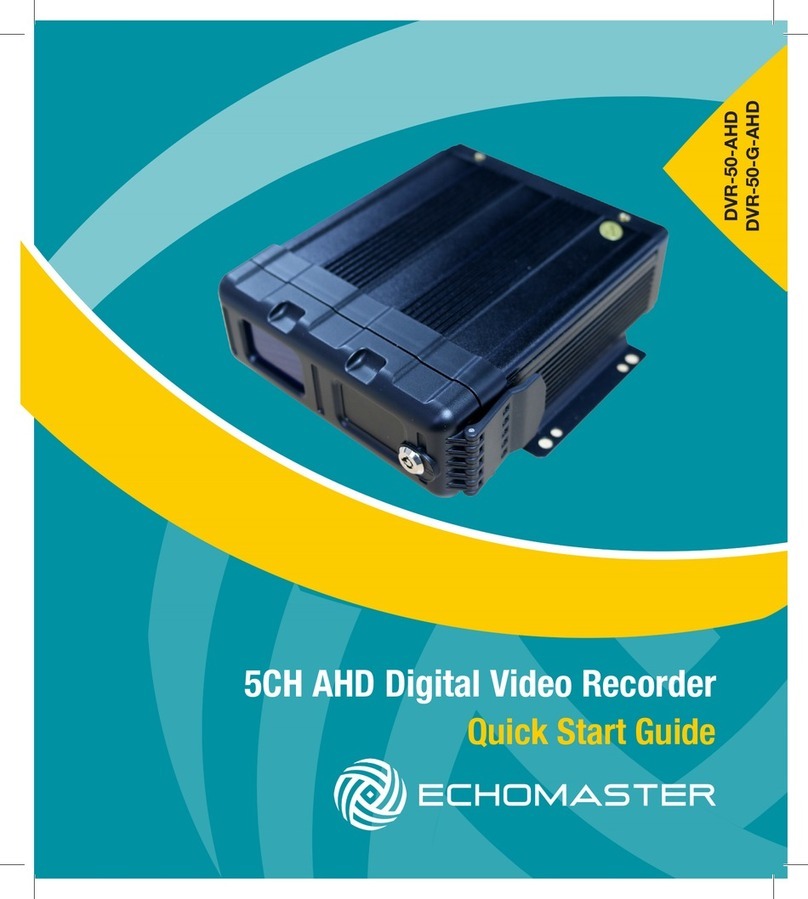
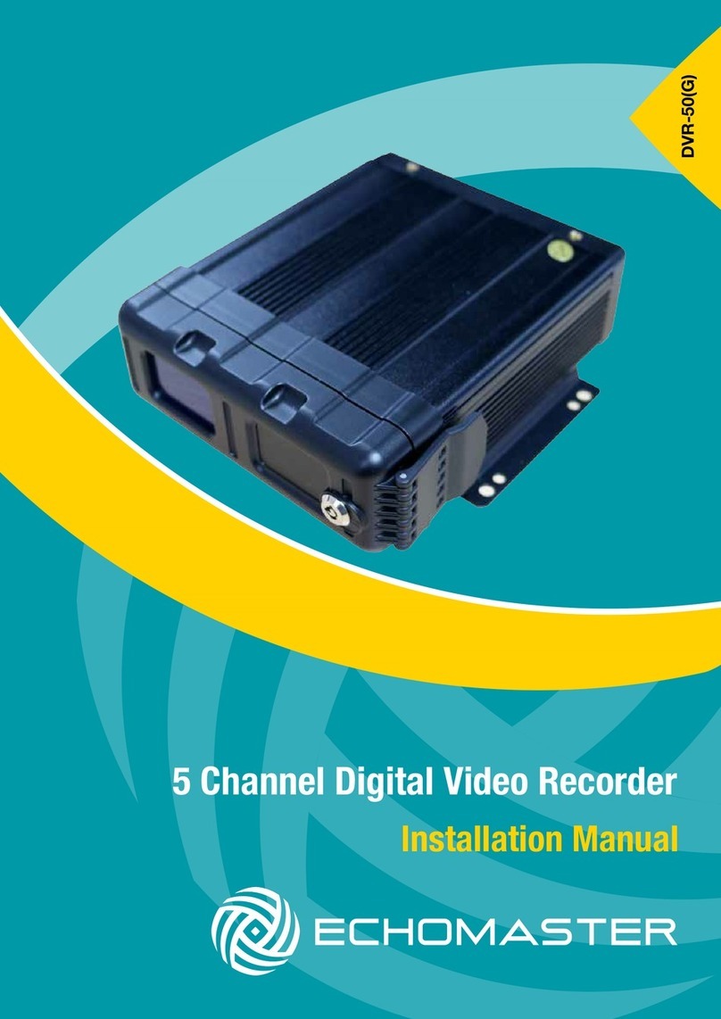
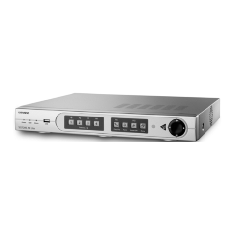
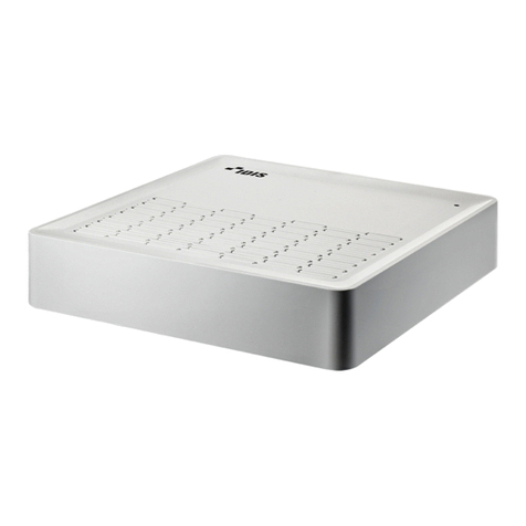
Echomaster DVR-50 User manual

User Manual MOBILE DVR RANGE
W: EchoMaster-eu.com
T: +44(0)1420 487110
Installation Manual
EchoMaster DVR Range
DVR
RANGE

User Manual MOBILE DVR RANGE
W: EchoMaster-eu.com
T: +44(0)1420 487110
Introduction Page
Front Panel Layout Page
Dimensions Page
Installation Page
-DVR-50-TH-CAB - For the DVR-50 & 150 range (optional) Page
- DVR-50-TH-CAB - Wiring Diagram Page
- DVR-350-TH-CAB - For the DVR-350 range (optional) Page
- DVR-350-TH-CAB - Wiring Diagram Page
- DVR-350-SR-CAB - For the DVR-350 range (optional) Page
- DVR-350-SR-CAB - Wiring Diagram Page
- DVR-380-TH-CAB - For the DVR-380 range (optional) Page
- DVR-380-TH-CAB - Wiring Diagram Page
- DVR-580-TH-CAB - For the DVR-580 range (optional) Page
Initial Setup Page
Menu Function Page
- Main Menu Page
- Home Menu Page
- REC Search Page
- Log Search Page
- System Page
- Setup Page
- Log Out Page
Basic Setup Page
- Registered Info Page
- Device Info Page
- Vehicle Info Page
- Driver Info Page
- Time Setup Page
- General Page
- Time sync Page
- DST Page
Contents
6
6
9
11
16
16
17
17
18
18
19
19
20
21
22
22
23
23
24
24
24
24
25
25
25
25
25
25
25
25
25

User Manual
MOBILE DVR RANGE
3
W: EchoMaster-eu.com
T: +44(0)1420 487110
Basic Setup (continued)
- Startup Page
- On/Off Page
- Mode Page
- Ignition Display Page
- Timer Page
- Light off time Page
- Sleep Page
- Sleep Mode Page
- Low Voltage protect Page
- Battery low voltage protect Page
- Voltage startup Page
- Low volt upload Page
- User Setup Page
- Idle Time Page
- Users Page
- Network Page 26
- Application & Other Setup Page
- Surveillance Page
- Live View Page
- Preview Page
- Preview Audio Page
- Image Setup Page
- Margins Page
- Startup screen Page
- Auto Loop Page
- Live OSD Page
- Record Page
- General Page
- System Page
- Overwrite Page
- Lock Duration Page
- Pre-recording Page
25
25
25
26
26
26
26
26
26
26
26
26
26
26
26
28
29
29
29
29
29
29
29
29
30
30
30
30
30
30
30
Contents

User Manual MOBILE DVR RANGE
W: EchoMaster-eu.com
T: +44(0)1420 487110
Basic Setup (continued)
- Main Stream Page 30
- Channel Page 30
- Channel Name Page 30
- Enable Page 30
- Resolution Page 30
- Frame rate Page 30
- Quality Page 30
- Record Mode Page 30
- Audio Page 30
- Alarm Quality Page 30
- Encode Mode Page 30
- Dual Stream Page 31
- OSD Page 31
- Position Page 31
- IPC Setup Page 31
- PTZ Page 31
- Collection Page 32
- General Page 32
- Sensor Page 32
- Sensor Number Page 32
- Overwrite Page 32
- OSD name Page 32
- Serial Port Page 32
- Speed Page 32
- Navigation Page 32
- Mileage Page 32
- Source Page 32
- Total Page 32
- Base Value Page 32
- Operation Page 32
- Flow Limit Page 32
- Unit Page 32
Contents

User Manual
MOBILE DVR RANGE
5
W: EchoMaster-eu.com
T: +44(0)1420 487110
Basic Setup (continued)
- Snap Setting Page 33
- Time Snap Page 33
- Trigger Snap Page 33
- Snap Options Page 33
Alarm Page 34
- Base Page 34
- Speed Alarm Page 34
- Panel Alarm Page 34
- IO Alarm Page 34
- Video Page 35
- Video Loss Page 35
- Motion Page 35
- Cover Page 35
- Advanced Page 36
- Acc Alarm Page 36
- Electricfence Page 36
- Maintenance Page 37
- Cong Page 37
- File Data Page 37
- Upgrade Page 37
- Storage Page 37
- Reset Page 37
Ofine Video Playback Page 38
Specication Page 38
- Non-Connected Range Page 38
- Connected Range Page 39
References Page 42
- Storage Capacity Page 42
Contents

User Manual MOBILE DVR RANGE
W: EchoMaster-eu.com
T: +44(0)1420 487110
Introduction
Thank you for purchasing your EchoMaster Digital Video Recorder (DVR).
EchoMaster DVR’s are specically designed for vehicle video surveillance and monitoring.
They are able to provide high resolution video recording of connected cameras, GPS location
information, trigger alerts and vehicle data (Model Dependant).
This manual covers all variants for the following models:
u DVR-50 u DVR-150 u DVR-350 u DVR-380 u DVR-580
Front Panel Layouts
DVR-50 Range
Power On
USB dongle inserted
Recording in progress
Operation Error
Network connected
SD & SIM Card Slots
Alarm Indicator
USB Port
LED
Indicators

User Manual
MOBILE DVR RANGE
7
W: EchoMaster-eu.com
T: +44(0)1420 487110
Front Panel Layouts - continued
DVR-150 Range
DVR-350 Range
Power On
HDD caddy
USB dongle inserted
Recording in progress
HDD caddy lock
Operation Error
Network connected
Alarm Indicator
USB Port
SIM and SD card slots
Status LED panel
USB port
HDD caddy

User Manual MOBILE DVR RANGE
W: EchoMaster-eu.com
T: +44(0)1420 487110
Front Panel Layouts - continued
DVR-580 Range
HDD caddy
Status LED panel
SIM and SD card slots
USB port
AV output
DVR-380 Range
Alarm Indicator
HDD caddy
USB port
Network
Operation Error
USB Status
Record Status
Power

User Manual
MOBILE DVR RANGE
9
W: EchoMaster-eu.com
T: +44(0)1420 487110
Dimensions
DVR-50
DVR-150
167.3
157.8
125.0
140.1
146.3
54.1
70.4
150.4
190
206
195.5
170
128.5
90
8.5
19.5

User Manual MOBILE DVR RANGE
10 E: [email protected]
W: EchoMaster-eu.com
T: +44(0)1420 487110
Dimensions - continued
DVR-350
DVR-380
DVR-580
150
131.5
255.3
141.8
89.1
281
157
41.5
150
167
295
80
50
200
206.5
222.5
89
92.8

User Manual
MOBILE DVR RANGE
11
W: EchoMaster-eu.com
T: +44(0)1420 487110
Installation
When choosing a mounting location, please ensure that there is sufcient access to the front panel of the
DVR to allow access to the storage media.
Also ensure that there are no electrical or uid lines behind any panels that are to be drilled that could
become punctured.
Once the mounting location has been decided, secure the unit with 4 screws.
Connect the main power harness to +12V (RED) IGN (YELLOW) and Ground (BLACK).
Make all camera connections before powering up the unit.
Connect and route the GPS antenna and 3G/4G antenna (if supplied) to a position where it has a clear and
unobstructed view of the sky. Any metalwork or large wiring looms above the antenna can obstruct its
operation.
A/V OUT IPC
+12V (RED)
(YELLOW)
IGN
(BLACK)
GND
IPC Camera in:
Up to 1080p resolution
Camera CH4 in:
Up to 1020p AHD resolution
Camera CH1 in:
Up to 1080p AHD resolution
Camera CH2 in:
Up to 1080p AHD resolution
Camera CH3 in:
Up to 1080p AHD resolution
A/V Out
DVR-50-TH-CAB
(optional)
GPS Antenna
AHD-1 AHD-2 AHD-3
AHD-4 POWER
Sensor & Serial
GPS
GSM/LTE Antenna
DVR-50

User Manual MOBILE DVR RANGE
12 E: [email protected]
W: EchoMaster-eu.com
T: +44(0)1420 487110
DVR-150
+12V (RED)
(YELLOW)
IGN
(BLACK)
GND
IPC Camera in:
Up to 1080p resolution
Camera CH4 in:
Up to 1080p AHD resolution
Camera CH1 in:
Up to 1080p AHD resolution
Camera CH2 in:
Up to 1080p AHD resolution
Camera CH3 in:
Up to 1020p AHD resolution
A/V Out
DVR-50-TH-CAB
(optional)
GPS Antenna
GPS
GSM/LTE
Antenna

User Manual
MOBILE DVR RANGE
13
W: EchoMaster-eu.com
T: +44(0)1420 487110
DVR-350
GSM/LTE Antenna
Camera in:
Up to 1080 AHD
resolution
GPS Antenna DVR-FPBOX
(optional)
DVR-UPS
(optional)
+12V
(red)
GND
(black)
Video Output
DVR-350-TH-CAB (optional)
DVR-350-SR-CAB (optional)
MON-7010-TS Kit
(optional)
IGN
(yellow)
IPC Camera in:
Up to 1080 resolution
Microphone
Reverse camera input
Reverse trigger input

User Manual MOBILE DVR RANGE
14 E: [email protected]
W: EchoMaster-eu.com
T: +44(0)1420 487110
DVR-380
VGA Out (optional)
GPS Antenna
Camera in:
Up to 1080 AHD
resolution
GSM/LTE Antenna
DVR-380-TH-CAB (optional)
DVR-380-SR-CAB (optional)
IPC Camera in:
Up to 1080 resolution
DVR-FPBOX
(optional)
Microphone
Reverse
Camera Input
Reverse
Trigger Input
Camera in:
Up to 1080 AHD
resolution
MON-7010
(optional)
+12V (RED)
IGN (YELLOW)
GND (BLACK)

User Manual MOBILE DVR RANGE
15 E: [email protected]
W: EchoMaster-eu.com
T: +44(0)1420 487110
DVR-580
AV Out
VGA Out
(optional)
IPC Camera in:
Up to 1080 resolution
MON-7010TS Kit
(optional)
DVR-UPS
(optional)
GSM/LTE AntennaGPS Antenna
DVR-FPBOX
(optional)
DVR-580-TH
(optional)
IPC-PON-4
(optional)
Camera in:
Up to 1080 AHD
resolution
+12V
(red)
GND
(black)IGN
(yellow)
+12V
(red)
GND
(black)
IGN
(yellow)
Microphone
Reverse camera input
Reverse trigger input
Amplier Output

User Manual MOBILE DVR RANGE
16 E: [email protected]
W: EchoMaster-eu.com
T: +44(0)1420 487110
DVR-50-TH-CAB - For DVR-50 and 150 range
If using the DVR-50-TH then this should be connected at this time using the following instructions.
The DVR-50-TH adds the following functions to either the DVR-50 or DVR-150: 8 congurable trigger
inputs for external inputs, RS232 serial output, speed pulse input and an external mic input.
Follow the wiring diagram below for all connections.
Trigger 1 In (Green)
+5V Out
Mic
RS232
(Red)
(Black)
(Red/Yellow)
(Red/White)
(Blue)
(Blue/White)
(Blue/Black)
(Orange)
(Grey)
(Light Blue)
(Light Green)
(Grey)
GND Out
Trigger 2 Out
Trigger 1 Out
Speed In
Trigger 8 In
Trigger 7 In
Trigger 6 In
Trigger 5 In
Trigger 4 In
Trigger 3 In
Trigger 2 In
MIC SW IN (3) MIC - (4)
MIC + (1) +5V (2)
12
21 22
DVR-50-TH-CAB Wiring Diagram
Trigger IN: 1- 8 can be a high or low trigger value which is congured in the menu of the DVR.
Trigger OUT: 1 and 2 can be used to trigger external devices (such as a telematics device) when any
trigger input is activated. This is again congurable in the DVR-50(G) menu.
Speed input: Can be used to record speed information of the vehicle onto the recording captured on the
DVR. It should be connected to the analogue speed output wire on the vehicle (often found behind the
radio or instrument cluster).
RS232: Can be used to send and receive data from external devices.
The external mic input can be used to record separate audio to that of the mic normally housed in the
cameras.

User Manual
MOBILE DVR RANGE
17
W: EchoMaster-eu.com
T: +44(0)1420 487110
DVR-50-TH-CAB - For DVR-50 and 150 range DVR-350-TH-CAB - For DVR-350 range
If using the DVR-350-TH then this should be connected at this time using the following instructions.
The DVR-350-TH adds the following functions to the DVR-350:
u 8 x congurable trigger inputs for external inputs u 2 x congurable alarm outputs
u Speed pulse input u 1 x 12v output.
Follow the wiring diagram below for all connections.
DVR-350-TH-CAB Wiring Diagram
Trigger IN: 1- 8 can be a high or low trigger value which is congured in the menu of the DVR-350.
Trigger OUT: 1 & 2 can be used to trigger external devices (such as a telematics device) when any trigger
input is activated. This is again congurable in the DVR-350 menu.
Speed Input: Can be used to record speed information of the vehicle onto the recording captured on the
DVR-350. It should be connected to the analogue speed output wire on the vehicle (often found behind
the radio or instrument cluster).
Trigger 1 In
1 2
21 22
(Green)
Speed in (Blue)
GND out (Black)
(Blue/Black)
(Blue/Black)
(Black)
(Red)
(Yellow)
(Pink)
(Light Green)
(Grey)
(Light Blue)
(Purple)
(Orange)
Trigger 2 out
Trigger 1 out
GND out
+12V out
Trigger 8 In
Trigger 7 In
Trigger 6 In
Trigger 5 In
Trigger 4 In
Trigger 3 In
Trigger 2 In

User Manual MOBILE DVR RANGE
18 E: [email protected]
W: EchoMaster-eu.com
T: +44(0)1420 487110
DVR-350-SR-CAB - For DVR-350 range
If using the DVR-350-SR then this should be connected at this time using the following instructions.
The DVR-350-SR adds the following functions to the DVR-350:
u 2 x RS232 inputs u 2 x RS485 inputs u 1 x 5v output
Follow the wiring diagram below for all connections.
DVR-350-SR-CAB Wiring Diagram
RS232: Can be used to send and receive data from external devices.
RS485: Can be used to send and receive data from external devices.
RS232 TX -1
1 2
11 12
(Red)
(Black)
(White/Yellow)
(White/Red)
(White/Blue)
(Green/Yellow)
(Green/Blue)
(Green/Black)
(White/Black)
(Green/Red)
RS 485B -2
RS 485A -2
RS 485B -2
RS 485A -1
GND out
+5V out
RS232 RX -2
RS232 TX -2
RS232 RX -1

User Manual
MOBILE DVR RANGE
19
W: EchoMaster-eu.com
T: +44(0)1420 487110
DVR-380-TH-CAB - For DVR-380 devices
If using the DVR-380-TH-CAB, then this should be connected using the following guidelines
The DVR-380-TH-CAB adds the following functionality to the DVR.
u 8 x Congurable trigger inputs u 2 x Congurable alarm outputs
u Speed pulse input u 1 x +12v accessory power output
Follow the wiring diagram below for all connections.
Trigger 1 In
1 2
21 22
(Green)
Speed in (Blue)
GND out (Black)
(Blue/Black)
(Blue/Black)
(Black)
(Red)
(Yellow)
(Pink)
(Light Green)
(Grey)
(Light Blue)
(Purple)
(Orange)
Trigger 2 out
Trigger 1 out
GND out
+12V out
Trigger 8 In
Trigger 7 In
Trigger 6 In
Trigger 5 In
Trigger 4 In
Trigger 3 In
Trigger 2 In
Trigger IN: 1- 8 can be a high or low trigger value which is congured in the menu of the DVR-380.
Trigger OUT: 1 & 2 can be used to trigger external devices (such as a telematics device) when any trigger
input is activated. This is again congurable in the DVR-380 menu.
Speed Input: Can be used to record speed information of the vehicle onto the recording captured on the
DVR-380. It should be connected to the analogue speed output wire on the vehicle (often found behind
the radio or instrument cluster).
DVR-380-TH-CAB - Wiring Diagram

User Manual MOBILE DVR RANGE
20 E: [email protected]
W: EchoMaster-eu.com
T: +44(0)1420 487110
DVR-580-TH-CAB - For DVR-580 range
DVR-580-TH-CAB Wiring Diagram
Trigger IN: 1- 8 can be a high or low trigger value which is congured in the menu of the DVR-350.
Trigger OUT: 1 & 2 can be used to trigger external devices (such as a telematics device) when any trigger
input is activated. This is again congurable in the DVR-350 menu.
Speed Input: Can be used to record speed information of the vehicle onto the recording captured on the
DVR-350. It should be connected to the analogue speed output wire on the vehicle (often found behind
the radio or instrument cluster).
RS232: Can be used to send and receive data from external devices.
RS485: Can be used to send and receive data from external devices.
If using the DVR-580-TH then this should be connected at this time using the following instructions.
The DVR-580-TH adds the following functions to the DVR-580:
u 8 x congurable trigger inputs for external inputs u 2 x congurable alarm outputs
u Speed pulse inputs u 12v & 5v outputs
u RS232 inputs u RS485 inputs
Follow the product labelling for all connections.
GND GND
232RXD-2 232RXD-1
232TXD-2 232TXD-1
+12V +12V
+5V +5V
485A-2 485A-1
485B-2 485B-1
GND GND
Sensor _IN1
Sensor _IN12
Sensor _IN3
Sensor _IN4
Sensor _OUT2
Sensor _OUT1
Sensor _IN5
Sensor _IN6
Sensor _IN7
GND
GND
+12V
+5V
Speed-
Sensor_IN8 Speed+
Other manuals for DVR-50
1
This manual suits for next models
18
Table of contents
Other Echomaster DVR manuals
