Echomaster DVR-50 User manual

Installation Guide
1
Installation Manual
5 Channel Digital Video Recorder
DVR-50(G)

Installation Guide
2
Contents
DVR-50 (G)
5 Channel DVR Recorder
Introduction Page 6
- Key Features & Box Contents Page 6
Front Panel Layout Page 6
Dimensions Page 7
Installation Page 8
- DVR-50-TH (optional) Page 9
- DVR-50-TH Wiring Diagram Page 9
Initial Setup Page 10
Menu Page 10
- Main Menu Page 10
- Home Screen Page 11
- REC Search Page 12
- Log Search Page 12
- System Page 12
- Log Out Page 12
- Setup Page 12
- Basic Setup Page 13
- Regist Info Page 13
- Device Info Page 13
- Vehicle Info Page 13
- Driver Info Page 13
- Time Setup Page 13
- General Page 13
- Time sync Page 13
- DST Page 13
- Startup Page 13
- On/Off Page 13
- Mode Page 13
- Ignition Display Page 13
- Timer Page 13
- Light off time Page 13

Installation Guide
3
DVR-50 (G)
5 Channel DVR Recorder
- Startup (continued) Page 14
- Sleep Page 14
- Sleep Mode Page 14
- Low Voltage protect Page 14
- Battery low voltage protect Page 14
- Voltage startup Page 14
- Low volt upload Page 14
- User Setup Page 14
- Idle Time Page 14
- Users Page 14
- Network, Application & Other Setup Page 14
- Surveillance Page 15
- Live View Page 15
- Preview Page 15
- Preview Audio Page 15
- Image Setup Page 15
- Margins Page 15
- Startup screen Page 15
- Auto Loop Page 15
- Live OSD Page 15
- Record Page 16
- General Page 16
- System Page 16
- Overwrite Page 16
- Lock Duration Page 16
- Pre-recording Page 16
- Main Stream Page 16
- Channel Page 16
- Channel Name Page 16
- Enable Page 16
- Resolution Page 16
- Frame rate Page 16
- Quality Page 16
- Record Mode Page 16
Contents

Installation Guide
4
Installation Guide
DVR-50 (G)
5 Channel DVR Recorder
- Record Page 16
- Main Stream(continued) Page 16
- Audio Page 16
- Alarm Quality Page 16
- Encode Mode Page 16
- Resolution Page 16
- Frame rate Page 16
- Quality Page 16
- Record Mode Page 16
- Dual Stream Page 17
- OSD Page 17
- Position Page 17
- IPC Setup Page 17
- PTZ Page 17
- Collection Page 18
- General Page 18
- Sensor Page 18
- Sensor Number Page 18
- Overwrite Page 18
- OSD name Page 18
- Serial Port Page 18
- Speed Page 18
- Navigation Page 18
- Mileage Page 18
- Source Page 18
- Total Page 18
- Base Value Page 18
- Operation Page 18
- Snap Setting Page 18
- Alarm Page 19
- Base Page 19
- Speed Alarm Page 19
- Panel Alarm Page 19
- IO Alarm Page 19
Contents

Installation Guide
5
DVR-50 (G)
5 Channel DVR Recorder
- Video Page 20
- Video Loss Page 20
- Motion Page 20
- Cover Page 20
- Advanced Page 21
- Acc Alarm Page 21
- Electrifence Page 21
- Maintenance Page 21
- Cong Page 21
- File Data Page 21
- Upgrade Page 21
- Storage Page 21
- Reset Page 21
Video Playback Page 22
References Page 23
- Storage Capacity Page 23
- Recording File Size Calculation Page 23
Contents
Installation Guide
6
DVR-50 (G)
5 Channel DVR Recorder
Introduction
Box ContentsKey Features
Thank you for purchasing the EchoMaster DVR-50 Digital Video Recorder (DVR).
This system is specically designed for vehicle video surveillance.
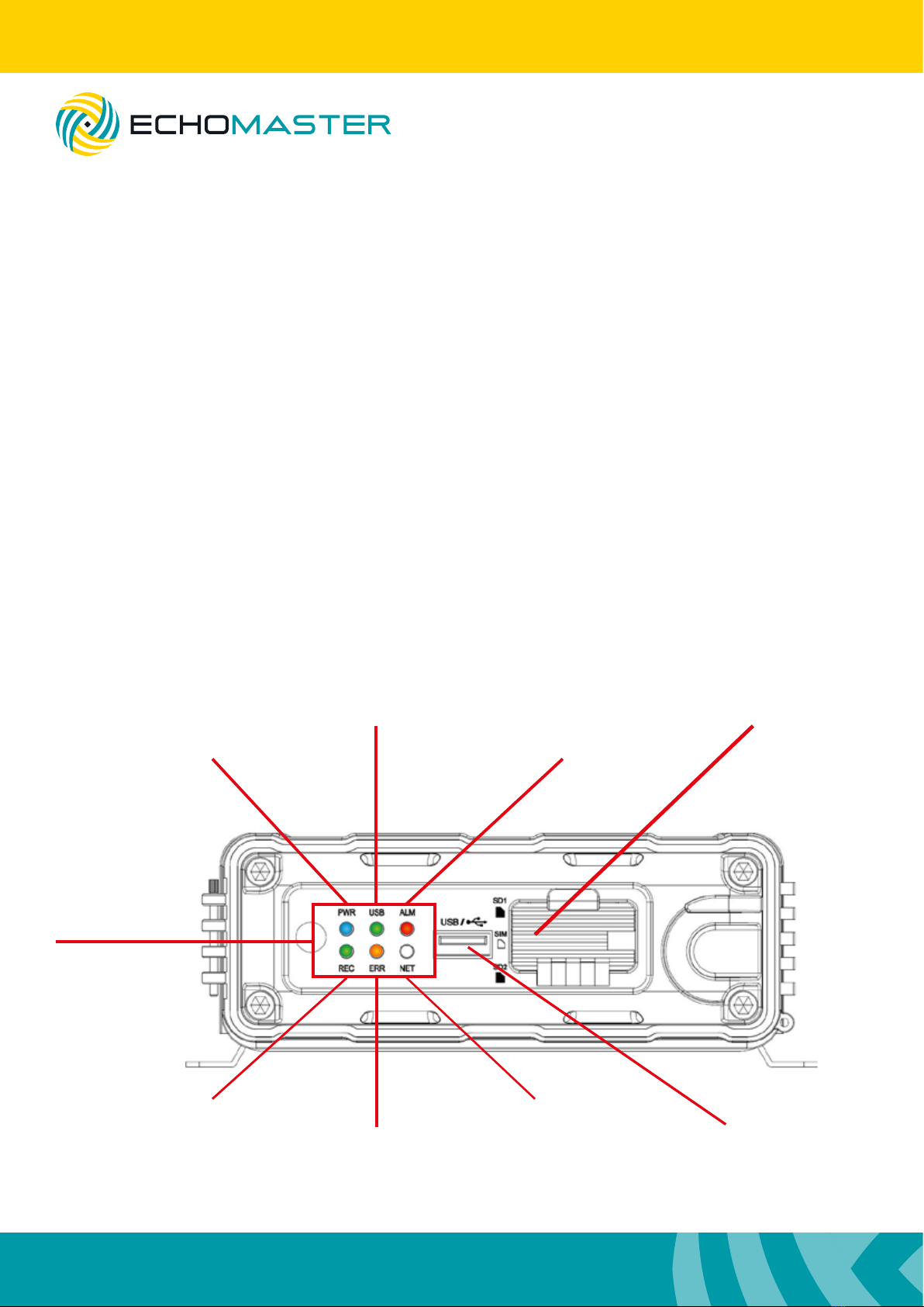
Power On
USB dongle inserted
Recording in progress
Operation Error
Network connected
SD Card Slots
Alarm Indicator
USB Port
Front Panel Layout
u Up to 256GB of ash storage
u Quad analogue inputs
u HD 5th channel input
u Optional external trigger module (DVR-50-TH)
u Optional GPS (DVR-50-G)
u Lockable cover
u DVR module
u GPS Antenna (DVR-50-G only)
u Power Cable
u GX16-RCA adapters x 5
u User Manual
LED Indicators

Installation Guide
7
DVR-50 (G)
5 Channel DVR Recorder
Dimensions (mm)
167.3
157.8
140.1
146.3
125125

Installation Guide
8
DVR-50 (G)
5 Channel DVR Recorder
When choosing a mounting location, please ensure that there is sufcient access to the front cover of the
DVR-50 to allow it to open.
Also ensure that there are no electrical or uid lines behind any panels that are to be drilled that could
become punctured.
Once the mounting location has been decided, secure the unit with 4 screws.
Connect the main power harness to +12V, IGN and Ground.
Make all camera connections before powering up the unit.
Connect and route the GPS antenna (DVR-50-G only) to a position where it has a clear and unobstructed
view of the sky. Any metalwork or large wiring looms above the antenna can obstruct its operation.
A/V OUT IPC
+12V (RED)
(YELLOW)
IGN
(BLACK)
GND
IPC Camera
Camera CH4
A/V Out to Monitor
DVR-50-TH
(optional)
Camera CH1
GPS Antenna
(DVR-50-G only)
Camera CH3
Camera CH2
A/V IN 4
A/V IN 1 A/V IN 2 A/V IN 3
POWER
Sensor & Serial
GPS
Installation

Installation Guide
9
DVR-50 (G)
5 Channel DVR Recorder
DVR-50-TH (optional)
If using the DVR-50-TH then this should be connected at this time using the following instructions.
The DVR-50-TH adds the following functions to either the DVR-50 or DVR-50-G: 8 congurable trigger
inputs for external inputs, RS232 serial output, speed pulse input and an external mic input.
Follow the wiring diagram below for all connections.
Trigger 1 In (Green)
+5V Out
Mic
RS232
(Red)
(Black)
(Red/Yellow)
(Red/White)
(Blue)
(Blue/White)
(Blue/Black)
(Orange)
(Grey)
(Light Blue)
(Light Green)
(Grey)
GND Out
Trigger 2 Out
Trigger 1 Out
Speed In
Trigger 8 In
Trigger 7 In
Trigger 6 In
Trigger 5 In
Trigger 4 In
Trigger 3 In
Trigger 2 In
MIC SW IN (3) MIC - (4)
MIC + (1) +5V (2)
12
21 22
DVR-50-TH Wiring Diagram
Trigger IN 1- 8 can be a high or low trigger value which is congured in the menu of the DVR-50(G).
Trigger Out 1 and 2 can be used to trigger external devices (such as a telematics device) when any trigger
input is activated. This is again congurable in the DVR-50(G) menu.
Speed input can be used to record speed information of the vehicle onto the recording captured on the
DVR-50(G). It should be connected to the analog speed output wire on the vehicle (often found behind the
radio or instrument cluster).
RS232 output can be used to send and receive data from external devices.
The external mic input can be used to record separate audio to that of the mic normally housed in the
cameras.
Installation Guide
10
DVR-50 (G)
5 Channel DVR Recorder
Initial Set-up
Power ON the unit with the door closed using the ignition.
Once it is powered up, open the door and plug a mouse into the USB port.
Right click the mouse and then click on the icon.
Use the password admin and click ‘LOGIN’
You will now have access to all the various features and settings of the unit.
Once initial setup is complete: unplug the mouse, insert the SD card(s), close and lock the door and you
are ready to start using the product.
Note:
It is always recommended to carry out a format on all SD cards using the internal format function
of the DVR before rst use.
Menu Function
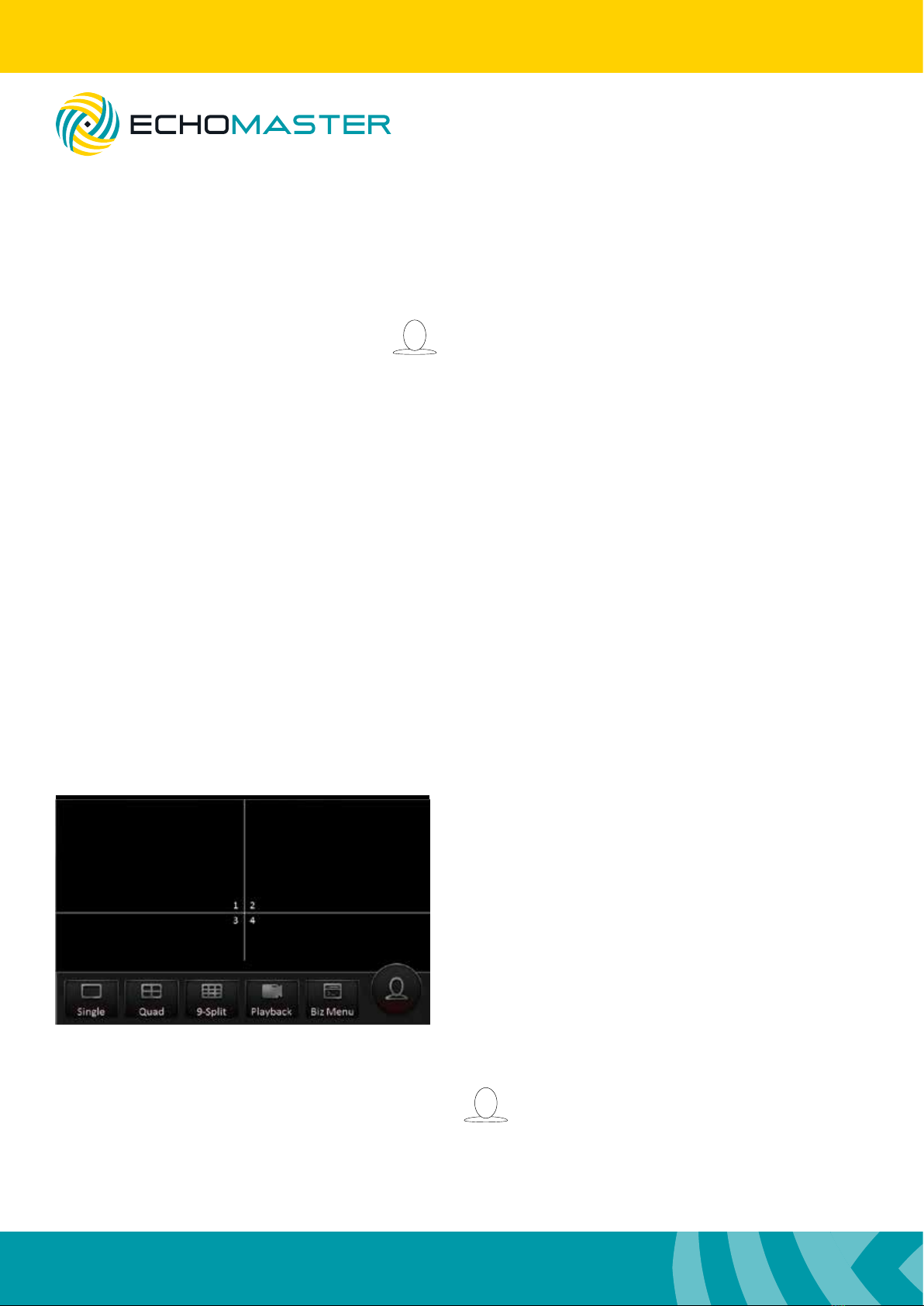
Main Menu
Using a right mouse click you can bring up the main
options. With these initial options you are able to select
the individual channel display option or you are also
able to choose 2 different split screen display options
(4-way and 9-way split).
Note: that in the 9-way split screen view only the rst
5 channels will be displayed.
Playback of the most recent le is also possible from
this screen by selecting the playback option.
All congurable options are accessed by clicking the icon to bring up the home menu.
The BIZ Menu requires a different version and is not used in this product.
Other manuals for DVR-50
1
This manual suits for next models
1
Table of contents
Other Echomaster DVR manuals


