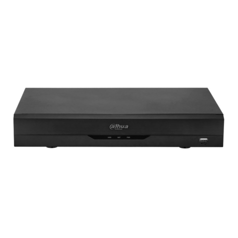
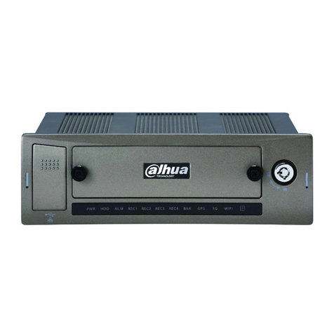
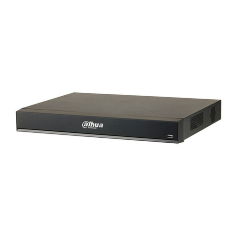
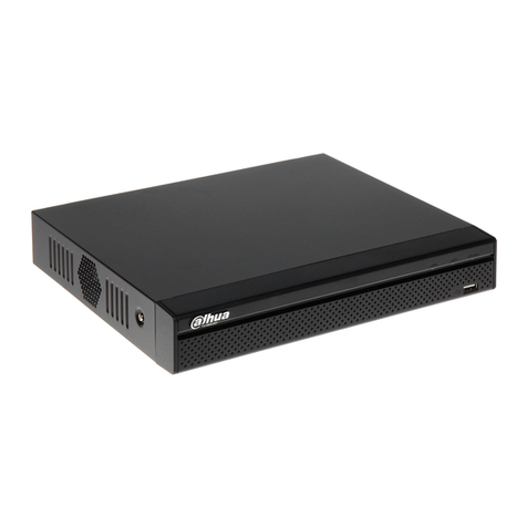
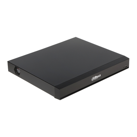
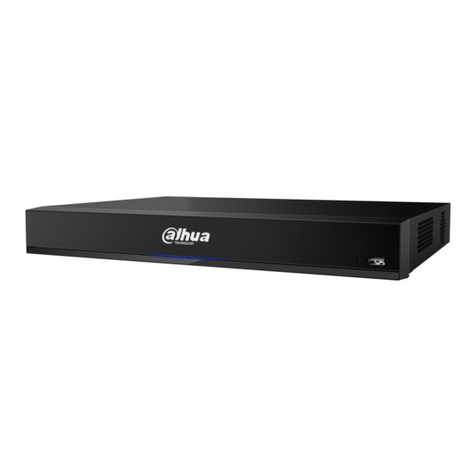
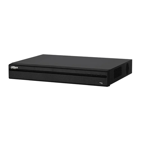
Dahua VEC0404HD-M70 User manual

Video Matrix Platform User’s Manual
V 1.0.0
Dahua Technology CO., LTD

i
Table of Contents
1PRODUCT OVERVIEW...........................................................................................................1
1.1 Introduction.........................................................................................................................1
1.2 Features...............................................................................................................................1
1.2.1 Structure...........................................................................................................................1
1.2.2 Hardware..........................................................................................................................1
1.2.3 Software...........................................................................................................................2
1.3 Introduction to Compression Cards in System .................................................................3
1.4 Host System........................................................................................................................3
1.4.1 4U Host ............................................................................................................................3
1.4.2 Main Control Panel ...........................................................................................................4
1.4.3 Control Panel....................................................................................................................5
1.5 Function Card......................................................................................................................6
1.5.1 VEC0404HD-M70 Video Matrix Platform 4-CH HD DVI Encoding Card.............................6
1.5.2 VEC0404HV-M70Video Matrix Platform 4-CH VGA Encoding Card...................................7
1.5.3 VEC0804HS-M70 Video Matrix Platform 8-CH HD SDI Encoding Card .............................8
1.5.4 VEC0804HC-M70 Video Matrix Platform 8-CH HDCVI Encoding Card..............................9
1.5.5 VDC0404D-M70 Video Matrix Platform 4-CH HD DVI Decoding Card.............................11
1.5.6 VDC0404V-M70 Video Matrix Platform HD VGA Decoding Card.....................................11
1.5.7 VS0201R-M70 Video Matrix Platform M70 Series RAID Card..........................................12
2OPEN-PACKAGE INSPECTION AND WIRING...................................................................14
2.1 Inspection Procedure........................................................................................................ 14
2.2 Accompanied Assessory Bag ..........................................................................................14
2.3 Device Installation............................................................................................................. 14
3LOCAL INTERFACE CONFIG..............................................................................................15
3.1 Software Interface Basic Operation .................................................................................15
3.1.1 Boot Up Device............................................................................................................... 15
3.1.2 Shut Down Device.......................................................................................................... 15
3.1.3 Enter System Menu ........................................................................................................15
3.1.4 Main Interface Introduction..............................................................................................17
3.1.5 Output Device Tree Introduction......................................................................................18
3.1.6 Input Device Tree Introduction ........................................................................................20
3.1.7 Display Control Area Introduction....................................................................................21
3.1.8 Display Setting................................................................................................................22
3.1.9 Input Group.....................................................................................................................26
ii
3.1.10 Scheme......................................................................................................................32
3.2 Advanced Menu Operation............................................................................................... 34
3.2.1 Menu Navigation.............................................................................................................34
3.2.2 Menu Operation..............................................................................................................35
3.2.3 Info.................................................................................................................................36
3.2.4 System Setting................................................................................................................41
3.2.5 Advanced .......................................................................................................................68
3.2.6 Remote Device...............................................................................................................79
3.2.7 Shutdown .......................................................................................................................81
4WEB OPERATION................................................................................................................82
4.1 Network Connection .........................................................................................................82
4.2 Login and Logoff............................................................................................................... 82
4.2.1 Matrix Control .................................................................................................................90
4.2.2 System Info.....................................................................................................................93
4.2.3 System Config................................................................................................................97
4.2.4 Advanced .....................................................................................................................125
4.3 Search ............................................................................................................................. 145
4.4 Alarm ...............................................................................................................................150
4.5 About...............................................................................................................................150
4.6 Log Out............................................................................................................................ 151
5DSS OPERATION...............................................................................................................152
6FAQ......................................................................................................................................153
6.1 FAQ.................................................................................................................................. 153
6.2 Maintenance.................................................................................................................... 156
APPENDIX A MOUSE CONTROL..............................................................................................157
APPENDIX B TOXIC OR HAZARDOUS MATERIALS OR ELEMENTS...................................159

iii
Welcome
Thank you for purchasing our Video Matrix Platform!
This user’s manual is designed to be a reference tool for the installation and operation of your
system.
Here you can find information about features and functions, as well as a detailed menu tree.
Before installation and operation please read the following safeguards and warnings carefully!

iv
Important Safeguards and Warnings
1.Electrical safety
All installation and operation here should conform to your local electrical safety codes.
We assume no liability or responsibility for all the fires or electrical shock caused by improper
handling or installation.
2.Transportation security
Heavy stress, violent vibration or water splash are not allowed during transportation, storage and
installation.
3.Installation
Keep the device upwards. Handle it with care.
Do not apply power to the device before completing installation.
Do not place objects on the device.
4.Qualified engineers needed
All the examination and repair work should be done by the qualified service engineers.
We are not liable for any problems caused by unauthorized modifications or attempted repair.
5.Environment
The device should be installed in a cool, dry place away from direct sunlight, inflammable,
explosive substances and etc.
6. Accessories
Be sure to use all the accessories recommended by manufacturer.
Before installation, please open the package and check all the components are included.
Contact your local retailer ASAP if something is broken in your package.
7. Lithium battery
Improper battery use may result in fire, explosion, or personal injury!
When replace the battery, please make sure you are using the same model!

1
1 Product Overview
1.1 Introduction
The Video Matrix Platform is designed by referring to ATCA (Advanced Telecommunications
Computing Architecture) as the modern telecommunication-level device which supersede DVR,
decoder, analog matrix, video wall controller and is compatible with past and current network
monitoring environments.
Main Application: flexible equipping of Function Card; supporting analog camera, HD-SDI
camera, input of various IPCs; outputs of BNC, VGA, HDMI, DVI. It achieves matrix switch,
encoding, decoding and etc. with these abundant interfaces. It supports analysis of video by
video intelligent analysis card, and network storage that leads to centralized storage
management. It also supports online real-time preview and optical cascading function of multiple
matrixes.
Figure 1- 1
1.2 Features
This product is a digital video matrix system with functions of digital video switch, multiple
operation insertion, centralized management, and distributed deployment. It achieves switches
among analog signal, digital signal, HD network signal and HD digital video signal and making
HD image available on video walls. It is a platform product integrating video signal
encoding/decoding, centralized data storage, online real-time preview and various networks, pre-
plan, log, user authority management, device maintenance functions and etc., which allows HD
video command/dispatch and video conference.
1.2.1Structure
19 inch 4U standard rack case for universal uses.
Card-type large scale ATCA structure for simple extension and flexibility.
2 groups of fans for intelligent temperature controlling, contributing to stabilized air passage
with the case structure to balance internal temperature.
Dual-channel redundant power supply for continuous working of device and security of data.
Double blade Function Card.
1.2.2Hardware

2
Intel x 86 Platforms for device expandability and fluency when system is in full load.
High speed connector on compression card, x4 PCI-E gen2,12V DC power supply, for
fluency of high speed data flow.
Compression card’s hot swap button and indicator for users’ flexible extension on the
application and knowledge of compression card status.
Various interfaces of compression card, such as USB, serial, Internet port, HDMI, BNC, DVI
and etc. which guarantee device functions and simplify operation and adjustment done by
users and technical staffs.
Each Function Card works independently to balance system’s work load and ensure fluency.
Duel-high-speed non blocking design for rear panel to meet demand of large volume A/V
data transmission.
1.2.3Software
Embedded LINUX OS: safe, stable, efficient, and easy for development and maintenance.
Video Encoding/Decoding
Each A/V encode card can support 32-ch of BNC or 8-ch of HD-SDI, 4-ch of DVI (supports
DVI, VGA, HDMI signal) and 8-ch of HDCVI.
Each A/V decode card can support 64-ch of D1 or 16-ch HD1080P decoding output.
Network Function
2 RJ45 interfaces, supporting 1000M network.
Support TCP/IP protocol including TCP,UDP,RTP,RTSP, PPPoE,DHCP,DNS,
DDNS,NTP,SADP,SMTP,ISCSI and etc.
Support NAS, IP SAN network centralized storage, and support receiving system log
remotely.
Support management software to achieve remotely switching between analog and digital
videos on video wall and control with keyboard.
Support remotely receiving and configuring parameter, remotely rebooting and remotely
inputting/outputting parameters.
Video Management
Support HD, SD digital matrix, and direct switch as non-compression bit stream which
eliminate image quality reduction after multiple switches of video signal.
Support HD, SD network IPC matrix.
Support digital video full crossing switch matrix, based on different applied compression card
combination, forming different digital video full crossing switch matrix with different
specifications.
A/V decode card supports HDMI, DVI, VGA and BNC interfaces support up to
1080P(1920*1080P) resolution output.
Allow operator to loop display different images on same screen, pre-set and switch as group.

3
Splicing image favorites, simplified operations on multiple video channels.
Other
Complete set of operation, alarm, abnormality and log recording, simplifying user and
technical staff’s maintenance.
Complete user authority management and storage management, while the authority can be
subdivided into a channel and a single HDD, making the device more user-friendly.
Support local and remote update, guaranteeing update to catch changing market demand.
Support network storage to accommodate demand from medium to large monitoring
systems.
Multiple users and clients login, convenient for users to preview and manage monitoring
whenever and wherever possible.
1.3 Introduction to Compression Cards in System
No.
Name
Model
Functional
Module
Description
Note
1
Platform
Host
Video Matrix
Platform-4U
Video matrix
platform host
1) 1 4U host,support 10
Function Cards
2)1 MBC0004 main
control panel
3)1 control panel
4)1 built-in power
adaptor (redundant)
Standard
(dual-
redundant
power
optional)
2
Input
Module
VEC0804HS-
M70
HD-SDI video
encoding card
1)8-ch HD-SDI video
input (BNC)
2)2-ch RS485 interface
Optional
VEC0404HD-
M70
HD DVI video
encoding card
4-ch DVI video input
Optional
(support
DVI, VGA,
HDMI)
VEC0804HC-
M70
HDCVI
encoding card
8-ch BNC video input
(HDCVI)
Optional
VEC0404HV-
M70
HD VGA
encoding card
4-ch VGA video input
Optional
3
Output
Module
VDC0404D-
M70
HD DVI
decoding card
4-ch DVI video output
port
Optional
VDC0404V-
M70
HD VGA
decoding card
4-ch VGA video output
port
Optional
4
RAID
Card
VS0201R-M70
RAID card
2-ch MINI, SAS port,
may connect to external
disk matrix
Optional
1.4 Host System
1.4.14U Host
Video matrix platform with 19 inch 4U structure host includes Function Card slot, power interface
and intelligent temperature-controlled fan. For product appearance, please see Figure 1- 2.

4
Figure 1- 2
Front panel, for displaying device working status;
ON/OFF button.
Device power indicator.
Off: Not operating after plugged in.
Red: Operating.
Device alarm indicator.
Red: Alarm on.
Off: Alarm off.
Device tatus indicator.
Yellow: Device is properly running.
Air intake of host with dust filter at rear;
Intelligent temperature-controlled fan, total of 2 groups, allow hot swap;
Function Card’s rear interface board slot, total of 10, labeled in sequence, for installation of
Function Card’s rear interface board;
Main control panel’s rear slot, marked as “M”;
Control panel’s rear slot, marked as “C”.
Duel-power module, support 220V modules.
1.4.2Main Control Panel
1.4.2.1 Interface Introduction
Please see Figure 1- 3.

5
Figure 1- 3
No.
Interface
Function
1
Reset Button
1, support restoring to default settings
2
Mainboard
Power Indicator
1, display mainboard power status
System Status
Indicator
1, display system working status
PCI-E Status
Indicator
1, display PCI-E working status
3
USB Port
3, as 1 USB 3.0 and 2 USB 2.0 for connection to mouse,
keyboard, USB
4
VGA
1, for local display output
5
Audio Input
1, for audio bidirectional talk
6
Audio Output
1, for audio bidirectional talk
7
Kilomega RJ45
Port
2, for transmission of network A/V data and network control
signal.
1.4.2.2 Features
High speed connector, including 10 x4 PCI-E gen2, 12V DC power, IIC
Memory slot, 1 single channel, 4G DDR3L memory
Fan interface, power/rotation rate control (CPU)
3 indicators (power indicator, system running status indicator, PCI-E status indicator)
1.4.3Control Panel
1.4.3.1 Interface Introduction
Please see Figure 1- 4.
Figure 1- 4
No.
Interface
Function
1
Clear Alarm
1, support to clear alarm

6
Button
2
Mainboard
Power Indicator
1, display mainboard power status
3
Alarm Indicator
1, display alarm status
4
System Status
Indicator
1, display system working status
5
RS232
1, DB9, debug serial or central control serial
6
RJ45 Port
3, for control of peripheral equipment
7
RS485
1
1.4.3.2 Features
Control device power up/down and working status monitoring
When system has alarm, via alarm clear button to clear alarm of the system
3 indicators (power indicator, system running status indicator, system alarm indicator)
Via RS232 serial connection with central control device or debug PC
Via RJ45 serial control peripheral equipment, such as analog matrix, wall and etc.
1.5 Function Card
Function Card adopts blade module design, and is mainly used to input analog, digital video and
centralize encoding compression, achieving remote preview, network centralized storage and etc.
1.5.1VEC0404HD-M70 Video Matrix Platform 4-CH HD DVI
Encoding Card
Please see Figure 1- 5.
.
Figure 1- 5
1.5.1.1 Main Features and Performance
Features
4-ch DVI-I video interface input, supporting HDMI, VGA and DVI input
2 buttons, hot swap
4 indicators
High speed connector, including x4 PCI-E gen2,12V DC power
Encoding Function

7
Support DVI HD input port: 1080P@60Hz, 1680*1050@60Hz, 1440*900@60Hz,
1366*768@60Hz, 1280*1024@60Hz, 1280*960@60Hz, 1280*800@60Hz, 1280*720@60Hz,
1152*864@60Hz, 1024*768@60Hz, 800*600@60Hz
Adopt H.264 video compression technology
Video encoding parameter is adjustable in each channel, including resolution, bit stream rate,
image quality and etc.
Each channel supports schedule and event as compression parameters
Support composite and bit stream encoding.
Support dual stream technology
Support picture compression in 4 CIF under JPEG standard or CIF and net transmission
Support watermark technology
1.5.1.2 Interface introduction
VIN video input interface, DVI-I interface
1.5.1.3 Technical Specifications
Model
VEC0404HD-M70
A/V Input
Video Input
4-ch, DVI-I
A/V
Encoding
Parameter
Video
Compression
Standard
H.264
Video
Encoding
Resolution
1080P, 1680*1050, 1440*900, 1366*768, 1280*1024,
1280*960, 1280*800, 1280*720, 1152*864, 1024*768, 800*600
Video Frame
PAL:1/16--25 frame/s, NTSC: 1/16--30 frame/s
Bit stream Rate
48Kbps-2048Kbps,customizable, max 4096Kbps
Dual Stream
Support
1.5.2VEC0404HV-M70Video Matrix Platform 4-CH VGA
Encoding Card
Please see Figure 1- 6.
Figure 1- 6
1.5.2.1 Main Features and Performance
Features
4-ch VGA video interface input, support VGA signal input
2 buttons, hot swap

8
4 indicators
High speed connector, including x4 PCI-E gen2,12V DC power
Encoding Function
VGA HD input port: UXGA@60Hz
1080P@60Hz,1080P@50Hz,720P@50Hz,720P@60Hz,1024x768@60Hz,1024x768@75Hz
,1280x1024@60Hz,1280x1024@75Hz;
Adopts H.264 video compression technology
Video encoding parameter is adjustable in each channel, including resolution, bit stream rate,
image quality and etc.
Each channel supports schedule and event as compression parameters
Support composite and bit stream encoding.
Support dual stream technology
Support picture compression in 4 CIF under JPEG standard or CIF and net transmission
Support watermark technology
1.5.2.2 Interface introduction
VIN video input interface, VGA interface
1.5.2.3 Technical Specifications
Model
VEC0404HV-M70
A/V Input
Video Input
4-ch, VGA
A/V
Encoding
Parameter
Video
Compression
Standard
H.264
Video
Encoding
Resolution
UXGA@60Hz,1080P@60Hz,1080P@50Hz,
720P@50Hz,720P@60Hz,1024x768@60Hz,
1024x768@75Hz,1280x1024@60Hz,1280x1024@75Hz;
Video Frame
PAL:1/16--25 frame/s, NTSC: 1/16--30 frame/s
Bit stream Rate
48Kbps-2048Kbps,customizable, max 4096Kbps
Dual Stream
Support
1.5.3VEC0804HS-M70 Video Matrix Platform 8-CH HD SDI
Encoding Card
Please see Figure 1- 7.
Figure 1- 7

9
1.5.3.1 Main Features and Performance
Features
8-ch HD-SDI video interface input
2-ch RS485 interface
2 buttons, hot swap
4 indicators
High speed connector, including x8 PCI-E gen2, 12V DC power
Encoding Function
Adopts H.264 video compression technology
Video encoding parameter is independently adjustable in each channel, including resolution,
frame rate, bit stream rate, image quality and etc.
Each channel supports schedule and event as compression parameters
Support composite and bit stream encoding, A/V are synchronized in composite.
Support dual stream technology
Support picture compression in 4 CIF under JPEG standard or CIF and net transmission
Support watermark technology
1.5.3.2 Interface Introduction
VIN video input interface, BNC interface
1.5.3.3 Technical Specifications
Model
VEC0804HS-M70
A/V Input
Video Input
8-ch SDI (BNC) (electrical level: 1.0Vp-p; impedance: 75Ω)
A/V
Encoding
Parameter
Video
Compression
Standard
H.264
Video
Encoding
Resolution
1080P/720P/D1/HD1/2CIF/CIF/QCIF
Video Frame
PAL:1/16--25 frame/s, NTSC: 1/16--30 frame/s
Bit stream Rate
48Kbps-4096Kbps,customizable, max 8192 Kbps
Dual Stream
Support
1.5.4VEC0804HC-M70 Video Matrix Platform 8-CH HDCVI
Encoding Card
Please see Figure 1- 8.
Figure 1- 8

10
1.5.4.1 Main Features and Performance
Features
8-ch BNC video input interface, support HDCVI signal input.
8-ch audio input, support external and built-in.
Countercharge
2 buttons, hot swap
4 indicators
High speed connector, including x4 PCI-E gen2, 12V DC power
Encoding Function
HDCVI HD input port 1080P@30Hz, 1080P@25Hz, 720P@60Hz, 720P@50Hz,
720P@30Hz, 720P@25Hz
Adopts H.264 video compression technology
Adopts G711a, PCM and G711u audio compression standard
Video encoding parameter is independently adjustable in each channel, including resolution,
frame rate, bit stream rate, image quality and etc.
Each channel supports schedule and event as compression parameters
Support composite and bit stream encoding, A/V are synchronized in composite.
Support dual stream technology
Support picture compression in 4 CIF under JPEG standard or CIF and net transmission
Support watermark technology
1.5.4.2 Interface Introduction
A/V input interface, BNC interface
1.5.4.3 Technical Specifications
Model
VEC804HC-M70
A/V Input
Video Input
8-ch BNC
Audio Input
8-ch HDCVI built-in
A/V
Encoding
Parameter
Video
Compression
Standard
H.264
Video
Encoding
Resolution
1080P/720P
Video Frame
PAL:1/16--25 frame/s, NTSC: 1/16--30 frame/s
Bit stream Rate
48Kbps-2048Kbps,customizable, max 4096 Kbps
Dual Stream
Support
Audio
Compresson
Standard
G711a, PCM, G711u
Audio Stream
Rate
8K16BIT

11
1.5.5VDC0404D-M70 Video Matrix Platform 4-CH HD DVI
Decoding Card
Please see Figure 1- 9.
Figure 1- 9
1.5.5.1 Main Features and Performance
Features
4-ch DVI digital video interface output
2 buttons, hot swap
4 indicators
High speed connector, including x4 PCI-E gen2, 12V DC power
Decoding Function
Support 64-ch D1 or 16-ch 1080p decoding output
Support 16-ch D1 uncompressed data output
Support DVI output interface 1080p@50/60Hz, 1280*720@50/60Hz, 1024*768@60Hz
Support hot swap
1.5.5.2 Interface Introduction
VOUT video output port, DVI port
1.5.5.3 Technical Specifications
Model
VDC0404D-M70
A/V Output
Video Output
4-ch DVI digital video port output
A/V
Decoding
Parameter
Video
Compression
Standard
H.264, MPEG4
Video
Decoding
Resolution
1920x1080/1280x1024/1280x720/1024x768
Video
Processing
Capacity
Support 64-ch 4CIF/24-ch HD 720P/16-ch HD 1080P image
decoding output; support 16-ch 4CIF or 4-ch HD original data
stream direct output
Bit stream Rate
48Kbps-4096Kbps,customizable, max 8192 Kbps
Image Display
Method
1, 4, 8,9,16 screen split
1.5.6VDC0404V-M70 Video Matrix Platform HD VGA
Decoding Card

12
Please see Figure 1- 10.
Figure 1- 10
1.5.6.1 Main Features and Performance
Features
4-ch VGA digital video interface output
2 buttons, hot swap
4 indicators
High speed connector, including x4 PCI-E gen2, 12V DC power,
Decoding Function
Support 64-ch D1 or 16-ch 1080p decoding output
Support 16-ch D1 uncompressed data output
Support VGA output interface 1080p@50/60Hz, 1280*720@50/60Hz, 1024*768@60Hz
Support hot swap
1.5.6.2 Interface Introduction
VOUT video output port, VGA port
1.5.6.3 Technical Specifications
Model
VDC0404V-M70
A/V Output
Video Output
4-ch VGA digital video port output
A/V
Decoding
Parameter
Video
Compression
Standard
H.264, MPEG4
Video
Decoding
Resolution
1920x1080/1280x1024/1280x720/1024x768
Video
Processing
Capacity
Support 64-ch 4CIF/24-ch HD 720P/16-ch HD 1080P image
decoding output; support 16-ch 4CIF or 4-ch HD original data
stream direct output
Bit stream Rate
48Kbps-4096Kbps,customizable, max 8192 Kbps
Image Display
Method
1, 4, 8,9,16 screen split
1.5.7VS0201R-M70 Video Matrix Platform M70 Series RAID
Card
Please see Figure 1- 11.

13
Figure 1- 11
1.5.7.1 Main Features and Performance
Features
2 MINI SAS ports, may connect to external disk matrix
1 button, hot swap
8indicators (MINI SAS work indicator)
High speed connector, including x4 PCI-E gen2, 12V DC power
Storage Function
Support raid0, raid1, raid5, raid6, raid10
Support two disk racks or up to 48 HDDs
Support max rate 6Gbps of each SAS port
Support 152-ch 1080P storage capacity
Data protection supports battery protection Cache
Support global hot spare
Support disk group management
1.5.7.2 Interface Introduction
MINI SAS port
1.5.7.3 Technical Specifications
Model
VS0201R-M70
Storage
Parameter
External Port
MINI SAS *2
RAID Mode
Raid0, raid1, raid5, raid6, raid10
Disk Rack
Support two disk racks
HDD
Max support 48 HDD
Port Rate
Each SAS port max rate is 6Gbps

14
2 Open-Package Inspection and Wiring
2.1 Inspection Procedure
When you receive video matrix platform, please check for obvious external damage. The material
of product package should be able to protect the product from majority impacts during
transportation.
Secondly please open the package, and check all accessories see if any part is missing. You
may refer to accompanied accessory bag. After you have checked that all parts are included, you
may remove protector on device.
Thirdly, please open device case to check front panel’s wiring, power line and see if the
connection between mainboard and interface board is loose.
2.2 Accompanied Assessory Bag
Accompanied assessory bag includes user’s manual and disk. When you unpackage the product,
please make sure all contents match the checklist.
2.3 Device Installation
At time of inserting mainboard and Function Card into chassis, please remove the protection
cover at connection interface of real panel.
In case of beep, it may be that either one of power modules is not well fixed. You may press
the small red button next to power module at the rear of device to cancel beep alarm.

15
3 Local Interface Config
3.1 Software Interface Basic Operation
3.1.1Boot Up Device
Plug in power line, and press power switch on front panel. Power indicator turns on and device
boots up followed by boot interface which lasts for 90s.
When you boot up device, please keep the following in mind:
1) Make sure whether the supplied voltage is within 100~240V 47~63Hz. Turn on the device
after you check power line connection.
2) We recommend you to use power supply with stable voltage and little interference (refer to
international standard), which benefit the device to work stably and last longer. This will also
benefit external devices such as camera. UPS is the best choice if possible.
3.1.2Shut Down Device
1. Enter main menu in shutdown system select shutdown device.
2. Press ON button on panel for 5s to shutdown.
Note:
Method 1 is recommended.
Stop all performance of the device, and then you may unplug the device from power
supply.
3.1.2.1 Outage Recovery
When the device is under working status, and there is an outage or forced shutdown, the
system can automatically save and resume previous working status after power recovery.
3.1.2.2 Replace Button Battery
Please make sure to use the same battery model if possible.
We recommend replace battery regularly (such as one-year) to guarantee system time
accuracy.
Note: Before replacement, please save the system setting, otherwise, you may lose the
data completely!
3.1.2.3
3.1.3Enter System Menu
After you properly turn on the device, system pops up the startup wizard. Click the Cancel button;
you can go to the system login interface. Click the Next Step button; you can go to the startup
wizard interface. Here you can set general, encode, schedule, record control, and network.
Please see Figure 3- 1.
Table of contents
Other Dahua DVR manuals

Dahua
Dahua MXVR4104-I Series User manual

Dahua
Dahua DH-M70-D-0204HO User manual

Dahua
Dahua XVR User manual

Dahua
Dahua DVR0404LBH-S User manual

Dahua
Dahua NVR1A-4P Series User manual

Dahua
Dahua DH-XVR5416L-X User manual

Dahua
Dahua XVR SERIES User manual

Dahua
Dahua NVS1604HF-A User manual

Dahua
Dahua PVR210 User manual

Dahua
Dahua HCVR5104C Series User manual

Dahua
Dahua X21A1E User manual

Dahua
Dahua DVR0X04AH-VD-E User manual

Dahua
Dahua DVR0404HD-S User manual

Dahua
Dahua N6 2U Series User manual

Dahua
Dahua HFD23 User manual

Dahua
Dahua NVR100 series User manual

Dahua
Dahua General 960H Mini 1U series User manual

Dahua
Dahua HCVR7416L User manual

Dahua
Dahua G4-HDE Series User manual

Dahua
Dahua DH-DVR3104 User manual