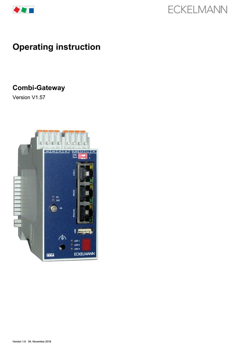
ECKELMANN LAN Gateway User manual

LAN Gateway Firmware V1.2 V1.825. April 2012
BOARD:DR.-ING. GERD ECKELMANN, CHAIRPERSON – DR. PETER CORDES, DR. FRANK-THOMAS MELLERT
CHAIRPERSOON OF THE SUPERVISORY BOARD: HUBERTUS G. KROSSA REGISTERED: DISTRICT COURT WIESBADEN HRB 12636
eckelmann.de
L AN G at e w a y
Firmware V 1.2
Operating Instruction

LAN Gateway Firmware V1.2 V1.8 25. April 2012
© 2012 – ECKELMANN AG | BERLINER STRASSE 161 | 65205 WIESBADEN | PHONE +49(0)611 7103-0 | FAX +49(0)611 7103-133 | eckelmann.de
2/34
Eckelmann Aktiengesellschaft
Business Unit Refrigeration and Building Management Systems
Berliner Straße 161
65205 Wiesbaden
Deutschland
Tel.: +49 611 7103-0
Fax: +49 611 7103-133
E-Mail: e.lds@eckelmann.de
Web : www.eckelmann.de
Information on safety and connection instructions are described in detail in the operating instruction
"Basics and General Safety and Connection Instructions".
All rights to any use whatever, utilisation, further development, forwarding and creation of copies
remain with the Eckelmann Aktiengesellschaft company.
In particular, neither the contract partners of Eckelmann Aktiengesellschaft nor other users have the right to
distribute or market the IT programs/program parts or modified or edited versions without express written
permission. To some extent, names of products/goods or designations are protected for the respective
manufacturer (registered trademarks etc.); in any case, no guarantee is assumed for their free
availability/permission to use them. The information provided in the description is given independently of any
existing patent protection or other third-party rights.
Before commissioning and use, please check that this is the latest version of the
document. With the publication of a new version of the documentation, all previous
versions lose their validity.
Errors and technical modifications are expressly reserved.

LAN Gateway Firmware V1.2 V1.8 25. April 2012
© 2012 – ECKELMANN AG | BERLINER STRASSE 161 | 65205 WIESBADEN | PHONE +49(0)611 7103-0 | FAX +49(0)611 7103-133 | eckelmann.de
3/34
1
Technical safety information...................................................................................5
2
Tasks of the LAN Gateway.....................................................................................6
2.1
Field of application ............................................................................................................................. 6
2.2
Use of the LAN gateway as an alarm path ........................................................................................7
3
New features compared to the previous version.....................................................7
4
Assembly and start-up of the LAN Gateways .........................................................8
4.1
Assembly and CAN bus connection................................................................................................... 8
4.2
Establishment of the serial connection for configuration ...................................................................9
4.2.1
Calling up and configurating the "HyperTerminal" terminal program...............................................10
4.2.2
Calling up the LAN Gateway's monitor interface.............................................................................. 11
4.3
Establishment of a serial connection................................................................................................13
4.4
Establishment of a network connection (LAN).................................................................................14
4.5
Configuration of the LAN gateway operating parameters................................................................15
4.5.1
Setting the IP address via the monitor interface (serial interface) ...................................................16
4.5.2
Configuration of the TCP/IP port......................................................................................................17
4.5.3
Configuration of the CAN bus address ............................................................................................18
4.5.4
Configuration of the automatic reboot interval .................................................................................19
4.5.5
Configuration of the trace level ........................................................................................................20
4.5.6
Overview of the system configuration ..............................................................................................21
4.5.7
Configuration of the node information and priority...........................................................................21
4.6
Updating the firmware via the monitor interface ..............................................................................22
4.6.1
Firmware version query....................................................................................................................22
4.6.2
Activation of the update mode over the monitor interface................................................................ 22
4.6.3
Updating the firmware......................................................................................................................23
5
Establishing a connection to LDSWin...................................................................25
5.1
Configuring the LAN connection to LDSWin.................................................................................... 25
5.1.1
Configuration of the LAN connection parameters............................................................................25
5.1.2
Direct connection with a PC via a network.......................................................................................25

LAN Gateway Firmware V1.2 V1.8 25. April 2012
© 2012 – ECKELMANN AG | BERLINER STRASSE 161 | 65205 WIESBADEN | PHONE +49(0)611 7103-0 | FAX +49(0)611 7103-133 | eckelmann.de
4/34
5.1.3
Configuration of the computer connection in LDSWin.....................................................................27
5.2
Configuring the serial connection to LDSWin ..................................................................................27
6
Important commands of the monitor interface ......................................................28
7
Status display of the operating states...................................................................30
8
LAN Gateway - technical details...........................................................................31
8.1
Electrical details ...............................................................................................................................31
8.2
Mechanical details............................................................................................................................31
Technical modifications and errors reserved! ......................................................................32
9
Appendix...............................................................................................................32
9.1
Commissioning checklist..................................................................................................................32
9.2
Terra Term – alternative terminal program for Windows Vista / Windows 7....................................33
9.2.1
Terra Term – configuration of the serial interface............................................................................33
10
Order numbers and accessories...........................................................................34
10.1
LAN-Gateway ...................................................................................................................................34
10.2
Accessories......................................................................................................................................34

LAN Gateway Firmware V1.2 V1.8 25. April 2012
© 2012 – ECKELMANN AG | BERLINER STRASSE 161 | 65205 WIESBADEN | PHONE +49(0)611 7103-0 | FAX +49(0)611 7103-133 | eckelmann.de
5/34
1 Technical safety information
1. Commissioning and operation of the device may only be performed by qualified
personnel. "Qualified personnel" as defined by this technical safety information
means persons who have the authorisation to start up, earth and designate devices,
systems and electric circuits in accordance with security technology standards.
2. Mounting, positioning and wiring may only be conducted when the electricity
supply to the assembly has been cut off.
3. The faultless and safe operation of the product presupposes proper transport,
appropriate storage, positioning and assembly, as well as careful operation and
maintenance.
4. Voltage must only be supplied by VDE-tested and CE-certified power packs.
5. Ensure that the voltage supply and the data cable are correctly connected.
6. If the product is brought into the working area from a cold environment,
condensation may form. The product must be completely dry before being
commissioned. Do not assemble or install the product near water or in damp
surroundings.
7. Do not take the product apart or remove the enclosure. The guarantee rights will
become invalid if the housing is opened.

LAN Gateway Firmware V1.2 V1.8 25. April 2012
© 2012 – ECKELMANN AG | BERLINER STRASSE 161 | 65205 WIESBADEN | PHONE +49(0)611 7103-0 | FAX +49(0)611 7103-133 | eckelmann.de
6/34
2 Tasks of the LAN Gateway
2.1 Field of application
The LAN Gateway is used to connect an E•LDS system to a network (LAN) for the purpose of local operation on
site (e.g. for the market manager), as well as for remote supervision and configuration. This TCP/IP-based form
of communication represents an alternative to transmission via serial interface, modem or CAN bus-PC adapter,
and it so helps the development towards a network-based communication solution:
It is possible to access the E•LDS system via a PC in the same network (local LAN) by means of the LDSWin
software. In addition, a connection can also be made via the LAN Gateway to an E•LDS system outside the
network boundaries. To do this, existing Internet connections can be used to access an E•LDS system from a
PC at another location.
Violation of data protection! The LAN gateway is not equipped with any security
mechanisms for the encryption of communication via the LAN interface. For this
reason connections should only be established in secure networks. For
communication via public or insecure networks additional security components (e.g.
VPN router etc.) should be employed.
Under no circumstances should the LAN gateway be connected directly with the
Internet.
CAN bus address conflict! The parallel operation of a LAN gateway and a PC-CAN
bus adapter is only possible when the CAN bus address for the LAN gateway is
configured to 127 (see section 4.5.3).

LAN Gateway Firmware V1.2 V1.8 25. April 2012
© 2012 – ECKELMANN AG | BERLINER STRASSE 161 | 65205 WIESBADEN | PHONE +49(0)611 7103-0 | FAX +49(0)611 7103-133 | eckelmann.de
7/34
Connection:
Simultaneous access to up to four clients is possible, of which three via LAN and one via serial connection.
Interfaces:
1x serial as per RS232 standard
1x serial reduced (Rx,Tx) to RS232 standard to CAN2 socket
1x CAN bus interface (RS-232)
1x Ethernet interface (RJ-45 / 10BASE-T)
Voltage supply:
The LAN Gateway is supplied with voltage via the type NT02 power pack (provided). The power pack is coupled
laterally (usually on the left) to the LAN Gateway and it must be supplied with 24 V DC of a separate power
supply (order no. KGLNT23024).
2.2 Use of the LAN gateway as an alarm path
On principle, the LAN gateway can be used as an alarm path. Alarm signalling can only be carried out in active
fetch mode. The precondition for this is a PC with the PC software LDSWin as remote station which can connect
to the LAN gateway via the network. This then calls up the alarms of the LDS system on a cyclical basis. The
LAN gateway is not equipped with an active transmission function for alarms.
The LAN gateway should not be used as the only alarm path. A second alarm path, employing a different
technology e.g. an uplink to the alarm system, telephone dialling device or similar, must be implemented.
When assessing the reliability of a network based alarm path the availability class of all participating
(sub)networks must be considered. As a rule Internet connections do not achieve the availability level of very
good telephone networks.
3 New features compared to the previous version
Version V1.2 of the LAN gateway offers the following new features compared to the previous version:
•Configuration of the TCP/IP port for communication via LAN. The TCP/IP port for communication via
LAN can now be freely configured, see chapter 4.5.2.
•The LAN gateway is now included in the monitoring of the system’s CAN bus nodes and is subject to
failure monitoring by the store computer (alternatively: AL 300), see chapter 4.5.7.
•A serial connection for the use of LDSWin can also be established, see chapter 5.2.
•The LAN gateway signals an existing CAN bus communication to the store computer by means of the
continuous illumination of the LED CAN BUS active (yellow).
•The LAN gateway is equipped with an option for monitoring the processing sequence by means of trace
messages. This function can be configured in detail via the so called trace level, see chapter 4.5.5.
•The configuration of the LAN gateway can be displayed on the monitor by calling up the function
“showsysconf“, see chapter 4.5.6.
•A ping command is available on the monitor for testing the network connection.

LAN Gateway Firmware V1.2 V1.8 25. April 2012
© 2012 – ECKELMANN AG | BERLINER STRASSE 161 | 65205 WIESBADEN | PHONE +49(0)611 7103-0 | FAX +49(0)611 7103-133 | eckelmann.de
8/34
4 Assembly and start-up of the LAN Gateways
4.1 Assembly and CAN bus connection
Before the LAN Gateway is started for the first time, it must be connected to the CAN bus via the Sub-D plug
(CAN2) on the front. To this end, a CAN bus connection must be interrupted (generally at the CI 3000 Store
Computer) and the CAN bus-Y cable supplied (1) must be inserted in between. Subsequently, the LAN gateway
must be supplied with 24 V DC (power supply order no. KGLNT23024):
To communicate within a network, the LAN Gateway needs an individual IP address,
including the corresponding subnet mask and a free TCP/IP port. If a connection is
made via a firewall, the port used must be released for the TCP/IP service.
These details must be obtained from the administrator of the network before
commissioning and configuring the LAN Gateway as described in section 4.5.1.
The LAN Gateway may only be integrated in the network once this has been done.
If a local, serial connection to a LDSWin PC is also required in parallel, then the
instructions in chapter 4.3 are to be followed. Specific details of connection to the
CAN bus (specifying the type of conductor, permissible conductor length, necessary
terminating resistors, and correct routing, etc.) are described in detail in the
operating instruction "Basics and General Safety and Connection Instructions".
Unprofessional shielding of the CAN bus leads to electromagnetic noise fields.
During wiring work, it is essential that the conductors be connected by a professional
and correctly shielded.

LAN Gateway Firmware V1.2 V1.8 25. April 2012
© 2012 – ECKELMANN AG | BERLINER STRASSE 161 | 65205 WIESBADEN | PHONE +49(0)611 7103-0 | FAX +49(0)611 7103-133 | eckelmann.de
9/34
4.2 Establishment of the serial connection for configuration
The LAN Gateway has an extended monitor interface with Z-modem file transfer. This is at the SUB-D socket
designated "RS232" on the front of the enclosure.
Via this interface with a Z-modem-capable terminal program
•the configuration of the LAN gateway is conducted
•the commands of the monitor interface can be used.
•software (e.g. Windows HyperTerminal) can be updated.
A null modem cable (1) is needed for a serial connection between the PC and the
LAN Gateway.

LAN Gateway Firmware V1.2 V1.8 25. April 2012
© 2012 – ECKELMANN AG | BERLINER STRASSE 161 | 65205 WIESBADEN | PHONE +49(0)611 7103-0 | FAX +49(0)611 7103-133 | eckelmann.de
10/34
4.2.1 Calling up and configurating the "HyperTerminal" terminal program
In the standard Windows installation 1 (for example, Windows 2000/XP), at
Start -> programs -> accessories -> communications -> HyperTerminal
a terminal program permits communication between the PC and the LAN Gateway via the serial interface
(by means of null modem cable).
After launching the program, a name must first be entered
(e.g. LAN Gateway) together with a symbol for the desired connection.
The port must be selected where the null modem cable is attached
(e.g. COM13, just like LDSWin).
The program first requests the various telephone connection settings
(country, region and area code). These details have no significance for
the connection with the LAN Gateway and they can therefore be selected
quite freely.
In the mask that will now open, the following settings can be made for the
serial interface.
1
In Widows Vista and higher, the HyperTerminal is no longer included. Alternatively, the program Terra Term mentioned in
chapter 9.2can be used.

LAN Gateway Firmware V1.2 V1.8 25. April 2012
© 2012 – ECKELMANN AG | BERLINER STRASSE 161 | 65205 WIESBADEN | PHONE +49(0)611 7103-0 | FAX +49(0)611 7103-133 | eckelmann.de
11/34
4.2.2 Calling up the LAN Gateway's monitor interface
While running, the Gateway (operational LED lit up) the monitor interface is activated by entering a question
mark "?", recognisable at the input prompt ">".
Step
PC procedure
1.
Start the PC; attach the serial null modem cable to the LAN Gateway.
2.
Call up the PC's terminal program (e.g. with Windows 2000/XP, you can find it at programs - >
accessories - > communications - > HyperTerminal)
3.
Ensure the terminal program is provided with the correct connection parameters (see section 3.2.1
).
4.
Enter “?” (hold keys) until the prompt symbol ">" appears:
ATTENTION: - once this succeeds, continue to point 6 .
- If the ">" symbol does not appear at the prompt, continue as described at point 5.

LAN Gateway Firmware V1.2 V1.8 25. April 2012
© 2012 – ECKELMANN AG | BERLINER STRASSE 161 | 65205 WIESBADEN | PHONE +49(0)611 7103-0 | FAX +49(0)611 7103-133 | eckelmann.de
12/34
5.
Restart the LAN Gateway by entering "reboot" and ENTER or by pressing the RESET key on the
enclosure. After the restart, enter “?” (hold keys) until the prompt symbol ">" appears.
6.
It is possible to enter monitor interface commands (e.g. "ver" and ENTER) (see also section 6)
7.
The monitor interface can be exited with ENTER.
The monitor interface has been left once the flashing cursor is not located on the same line as the ">
" prompt.
(The monitor interface ">" can be started at any time by enter "?" again)
8.
Following completion of the work, the program can be exited and the connection terminated.
The HyperTerminal session can be stored together with its connection parameters.

LAN Gateway Firmware V1.2 V1.8 25. April 2012
© 2012 – ECKELMANN AG | BERLINER STRASSE 161 | 65205 WIESBADEN | PHONE +49(0)611 7103-0 | FAX +49(0)611 7103-133 | eckelmann.de
13/34
4.3 Establishment of a serial connection
For a local connection between the LAN gateway and PC (LDSWin as remote station) an optionally available
accessorycable (article number LICANYKAB2) is required.
The connection is made via the SUB-D plug to the socket on the front of the housing labelled CAN2. This
interface can be used, amongst other things, for
•requesting data from the equipment of the E.LDS system,
•compiling daily temperature lists,
•configuring E.LDS components
•transmitting messages and alarms to the PC software LDSWin.
For the serial connection between the PC and the LAN gateway a special accessory
cable (2) is required, which must be connected as shown above.

LAN Gateway Firmware V1.2 V1.8 25. April 2012
© 2012 – ECKELMANN AG | BERLINER STRASSE 161 | 65205 WIESBADEN | PHONE +49(0)611 7103-0 | FAX +49(0)611 7103-133 | eckelmann.de
14/34
4.4 Establishment of a network connection (LAN)
For a local connection between the LAN Gateway and a PC, an Ethernet CAT5 crossover-patch cable is
needed:
ZNR. 51203 79 630 DEF
1
2
3
4
5
6
7
8
9
CAN2
RS232
Ethernet
LAN-
Gateway
+ 24 V DC
0 V
CAT5
Power
Supply
Crossover
LDSWin
A CAT5 Ethernet patch cable is required for a remote connection between the LAN Gateway and a PC via a
network.
ZNR. 51203 79 730 DEF
1
2
3
4
5
6
7
8
9
CAN2
RS232
Ethernet
LAN-
Gateway
+ 24 V DC
0 V
CAT5
Power
Supply
CAT5 Ethernet Patch
LDSWin
CAT5
CAT5 Ethernet Patch
LAN

LAN Gateway Firmware V1.2 V1.8 25. April 2012
© 2012 – ECKELMANN AG | BERLINER STRASSE 161 | 65205 WIESBADEN | PHONE +49(0)611 7103-0 | FAX +49(0)611 7103-133 | eckelmann.de
15/34
4.5 Configuration of the LAN gateway operating parameters
The connection to the monitor interface (serial console) for configuration purposes is carried out as described in
the subchapters 4.2. The most important operating parameters are:
•Setting the IP address via the monitor interface interface (serial interface) see chapter 4.5.1
•Configuration of the TCP/IP port see chapter 4.5.2
•Configuration of the CAN Bus address see chapter 4.5.3
•Configuration of the automatic reboot interval see chapter 4.5.4
•Configuration of the trace level see chapter 4.5.5
•Overview of the system configuration see chapter 4.5.6
•Configuration of the node information and priority see chapter 4.5.7
A list with all the commands available on the console can be found in chapter 5.

LAN Gateway Firmware V1.2 V1.8 25. April 2012
© 2012 – ECKELMANN AG | BERLINER STRASSE 161 | 65205 WIESBADEN | PHONE +49(0)611 7103-0 | FAX +49(0)611 7103-133 | eckelmann.de
16/34
4.5.1 Setting the IP address via the monitor interface (serial interface)
When delivered, the LAN Gateway has a specific, but randomly chosen IP address and subnet mask.
The correct IP address, subnet mask and possible also the Gateway address for the network is set via the LAN
Gateway's monitor interface (serial interface).
Step
PC procedure
1.
Activate the monitor interface as described in chapter 4.2.2.
2.
Enter the command “ipconf“ and ENTER in the console.
3.
The current IP configuration is displayed. Call up the dialog for entering a new IP configuration by
entering “y“ and ENTER or terminate the configuration by entering “n” and ENTER.
4.
If the dialog for entering a new configuration
is confirmed with “y“ and ENTER, then the
values for:
•IP address
•Subnet mask
•Gateway
are requested one after the other.
Each entry is to be confirmed with ENTER.
5.
Confirm changes by entering “y“ and ENTER or abort by entering “n“ and ENTER
False entries made during configuration can be rectified by repeating the
configuration procedure!

LAN Gateway Firmware V1.2 V1.8 25. April 2012
© 2012 – ECKELMANN AG | BERLINER STRASSE 161 | 65205 WIESBADEN | PHONE +49(0)611 7103-0 | FAX +49(0)611 7103-133 | eckelmann.de
17/34
4.5.2 Configuration of the TCP/IP port
For communication between the LAN gateway and LDSWin a defined TCP/IP port is needed. This can be freely
selected from the range of free ports (1024-65535) in accordance with the network requirements. As standard,
LDSWin uses the port 5000.
Step
PC procedure
1.
Activate the monitor interface as described in chapter 4.2.2.
2.
Enter the command “lgwportconf“ and ENTER in the console.
3.
The current port configuration is displayed. Call up the dialog for entering a new port configuration by
entering “y“ and ENTER or terminate the configuration by entering „n“ and ENTER.
4.
The port number can be freely selected from
the range of free ports (1024-65535).
The standard port for LDSWin is 5000 – in
the event of a different configuration
LDSWIn must be adjusted accordingly.
A change to the configuration leads to
a reboot of the LAN gateway.
5.
Confirm changes by entering “y“ and ENTER or abort by entering “n“ and ENTER
In the event of a faulty port configuration no communication between LDSWin and
the LAN gateway is possible!
The use of a “Well Known Port” (0-1023) can lead to communication problems and
should be avoided!
If a connection is made via a firewall the configured TCP/IP port must be released for
the TCP/IP service.
For the configuration of the port under LDSWin please refer to the LDSWin
documentation.

LAN Gateway Firmware V1.2 V1.8 25. April 2012
© 2012 – ECKELMANN AG | BERLINER STRASSE 161 | 65205 WIESBADEN | PHONE +49(0)611 7103-0 | FAX +49(0)611 7103-133 | eckelmann.de
18/34
4.5.3 Configuration of the CAN bus address
On leaving the factory, the LAN gateway is configured to the CAN bus address 127. This configuration enables
the parallel operation with one CAN bus-PC adapter (address 126). However in this configuration, no terminal
mode via the LAN gateway is possible with CI 3000 store computers older than the version 4.11. In this case,
the LAN gateway CAN bus address can be changed as described below. Parallel operation with a CAN bus-PC
adapter is then no longer possible due to the address conflict.
Step
PC procedure
1.
Activate the monitor interface as described in chapter 4.2.2.
2.
Enter the command “canconf“ and ENTER in the console.
3.
The current CAN bus address is displayed. Call up the dialog for entering a new CAN bus address by
entering “y“ and ENTER or terminate the configuration by entering „n“ and ENTER.
4.
Only the CAN bus addresses 126 or 127 can
be assigned.
Input scheme:
•0 => 126
•1 => 127
5.
Confirm changes by entering “y“ and ENTER or abort by entering “n“ and ENTER
The CAN bus address 126 is only designed for systems containing a store computer with a firmware version
lower than 4.17. However, in this case, an update of the store computer is preferable.
Due to restrictions in the firmware of the CI 3000 store computer a reliable
integration of the LAN gateway in the node monitoring function is only possible under
the CAN bus address 127!
Bei Vergabe der CAN-BUS-Adresse 126 muss die Priorität auf 0 (Meldeliste) gesetzt
werden!
The configuration of the CAN bus address has an effect on the behaviour of the LAN
gateway within the node monitoring and failure alarm functions. For a comprehensive
monitoring of the LAN gateway by the store computer and/or alarm terminals, the address
must be set to 127. See also chapter 4.5.7

LAN Gateway Firmware V1.2 V1.8 25. April 2012
© 2012 – ECKELMANN AG | BERLINER STRASSE 161 | 65205 WIESBADEN | PHONE +49(0)611 7103-0 | FAX +49(0)611 7103-133 | eckelmann.de
19/34
4.5.4 Configuration of the automatic reboot interval
The LAN gateway is equipped with an automatic reboot function. During operation unforeseen interruptions to
the LAN connection can occur. As a rule, these interruptions are detected by the LAN gateway and the
resources reactivated.
Additional reliability is provided by the configuration of the automatic reboot interval. After the elapse of the
interval, the LAN gateway carries out a reboot and initialising itself again. Active, existing connections are not
interrupted by the reboot as it is postponed until the active connections have been terminated.
The interval is entered in minutes.
Typical examples:
360 equivalent to 6 hours.
720 equivalent to 12 hours.
1440 equivalent to 24 hours.
Schritt
Vorgehensweise am PC
1.
Activate the monitor interface as described in chapter 4.2.2.
2.
Enter the command “autoreboot“ and ENTER in the console.
3.
The current reboot interval is displayed. Call up the dialog for entering a new reboot interval by
entering “y“ and ENTER or terminate the configuration by entering „n“ and ENTER.
4.
The interval is entered in minutes.
Entering the value “0“ deactivates the
automatic reboot of the LAN gateway.
5.
Confirm changes by entering “y“ and ENTER or abort by entering “n“ and ENTER
If there is a permanent connection between the LAN gateway and an LDSWin PC, the
cyclical call-up of data will deactivate the automatic reboot mechanism! In this case the
interval can be set to the value “0”.

LAN Gateway Firmware V1.2 V1.8 25. April 2012
© 2012 – ECKELMANN AG | BERLINER STRASSE 161 | 65205 WIESBADEN | PHONE +49(0)611 7103-0 | FAX +49(0)611 7103-133 | eckelmann.de
20/34
4.5.5 Configuration of the trace level
The LAN gateway is equipped with a trace interface on the monitor interface. If a serial connection is
established – as described in chapter 4.2 – then trace messages are displayed on the monitor interface in
accordance with the configuration of the trace level.
The available trace levels are as follows:
0 => OFF No messages are displayed on the console.
1 => Error level Only error messages are displayed on the console.
2 => Debug level Additional debug information is also displayed.
3 => Info level Additional extended debug information is also displayed.
4 => Development level Additional information on the data structure is also displayed.
Schritt
Vorgehensweise am PC
1.
Activate the monitor interface as described in chapter 4.2.2.
2.
Enter the command “tracelevel“ and ENTER in the console.
3.
The current trace level is displayed. Call up the dialog for entering a new trace level by entering “y“
and ENTER or terminate the configuration by entering „n“ and ENTER.
4.
Under normal operation the trace level
should be set to 1 = error level.
The stages 3 and 4 are very display
intensive – only to be activated for active,
on-site error detection!
5.
Confirm changes by entering “y“ and ENTER or abort by entering “n“and ENTER
For service and error detection purposes, the trace information displayed on the monitor
interface can be recorded. This requires the activation of the recording function for the
terminal program employed (e.g. HyperTerminal).
For information on recording the console contents please refer to the documentation for
the corresponding terminal program.
Table of contents
Other ECKELMANN Gateway manuals
Popular Gateway manuals by other brands

TEKTELIC Communications
TEKTELIC Communications Kona Mega Gateway quick start guide
ZyXEL Communications
ZyXEL Communications ZyXEL ZyWALL 5 user guide
Wildix
Wildix W04FXS Quick installation guide
enphase
enphase CT-100-SPLIT ROW Installation instruction
M2M
M2M IDG500AM-0T001 user manual
Honeywell
Honeywell LyricLCP300-L Installation and reference guide
