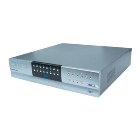
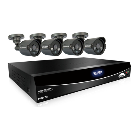
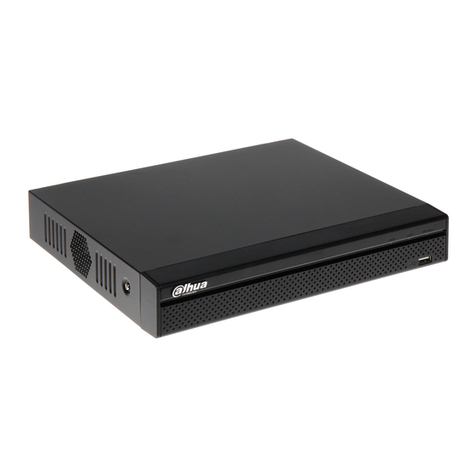
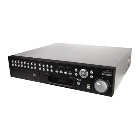
Eclipse Security Nubix HD Series User manual

HD Series
Digital Video Recorder
USER’S MANUAL

WARNING
RISK OF ELECTRIC SHOCK
DO NOT OPEN
WARNING: TO REDUCE THE RISK OF ELECTRIC SHOCK,
DO NOT REMOVE COVER (OR BACK).
NO USER-SERVICEABLE PARTS INSIDE.
The l ghtn ng flash w th arrowhead symbol, w th n an equ lateral tr angle, s ntended to alert the user to the presence
of un nsulated “dangerous voltage” w th n the product’s enclosure that may be of suff c ent magn tude to const tute
a r sk of electr c shock.
The exclamat on po nt w th n an equ lateral tr angle s ntended to alert the user to the presence of mportant
operat ng and
Ma ntenance (serv c ng) nstruct ons n the l terature accompany ng the appl ance.
1
COMPLIANCE NOTICE OF FCC:
THIS EQUIPMENT HAS BEEN TESTED AND FOUND TO COMPLY WITH THE LIMITS FOR A CLASS A DIGITAL
DEVICE, PURSUANT TO PART 15 OF THE FCC RULES. THESE LIMITS ARE DESIGNED TO PROVIDE
REASONABLE PROTECTION AGAINST HARMFUL INTERFERENCE WHEN THE EQUIPMENT IS OPERATED
IN A COMMERCIAL ENVIRONMENT. THIS EQUIPMENT GENERATES, USES, AND CAN RADIATE RADIO
FREQUENCY ENERGEY AND IF NOT INSTALLED AND USED IN ACCORDANCE WITH THE INSTRUCTION
MANUAL, MAY CAUSE HARMFUL INTERFERENCE TO RADIO COMMUNICATIONS. OPERATION OF THIS
EQUIPMENT IN A RESIDENTIAL AREA IS LIKELY TO CAUSE HARMFUL INTERFERENCE, IN WHICH CASE
USERS WILL BE REQUIRED TO CORRECT THE INTERFERENCE AT THEIR OWN EXPENSE.
CAUTION: CHANGES OR MODIFICATIONS NOT EXPRESSLY APPROVED BY THE PARTY RESPONSIBLE
FOR COMPLIANCE COULD VOID THE USER’S AUTHORITY TO OPERATE THE EQUIPMENT.
THIS CLASS OF DIGITAL APPARATUS MEETS ALL REQUIREMENTS OF THE CANADIAN INTERFERENCE-
CAUSING EQUIPMENT REGULATIONS.
The nformat on n th s manual s bel eved to be accurate as of the date of publ cat on. The
nformat on conta ned here n s subject to change w thout not ce. Rev s ons or new ed t ons to th s
publ cat on may be ssued to ncorporate such changes.

IMPORTANT SAFEGUARDS
1. Read Instruct ons
All the safety and operat ng nstruct ons should be read before the
appl ance s operated.
2. Reta n Instruct ons
The safety and operat ng nstruct ons should be reta ned for future
reference.
3. Clean ng
Unplug th s equ pment from the wall outlet before clean ng t. Do not
Use l qu d aerosol cleaners. Use a damp soft cloth for clean ng.
4. Attachments
Never add any attachments and/or equ pment w thout the approval of
The manufacturer as such add t ons may result n the r sk of f re,
electr c shock or other personal njury.
5. Water and/or Mo sture
Do not use th s equ pment near water or n contact w th water.
6. Accessor es
Do not place th s equ pment on an unstable cart, stand or table. The
equ pment may fall, caus ng ser ous njury to a ch ld or adult, and
ser ous damage to the equ pment. Wall or shelf mount ng should
follow the manufacturer’s nstruct ons, and should use a mount ng k t
approved by the manufacturer.
7. Power Sources
Th s equ pment should be operated only from the type of power source
Ind cated on the mark ng label. If you are not sure of the type of power,
13. Damage requ r ng Serv ce
Unplug th s equ pment from the wall outlet and refer serv c ng to
qual f ed serv ce personnel under the follow ng cond t ons:
A. When the power-supply cord or the plug has been damaged.
B. If l qu d s sp lled, or objects have fallen nto the equ pment.
C. If the equ pment has been exposed to ra n or water.
D. If the equ pment does not operate normally by follow ng the
operat ng nstruct ons, adjust only those controls that are covered by
the operat ng nstruct ons as an mproper adjustment of other
controls may result n damage and w ll often requ re extens ve work
by a qual f ed techn c an to restore the equ pment to ts normal
operat on.
E. If the equ pment has been dropped, or the cab net damaged.
F. When the equ pment exh b ts a d st nct change n performance —
th s nd cates a need for serv ce.
14. Replacement Parts
When replacement parts are requ red, be sure the serv ce techn c an
has
used replacement parts spec f ed by the manufacturer or that have the
same character st cs as the or g nal part. Unauthor zed subst tut ons
may result n f re, electr c shock or other hazards.
15. Safety Check
Upon complet on of any serv ce or repa rs to th s equ pment, ask the
serv ce techn c an to perform safety checks to determ ne that the
equ pment s n proper operat ng cond t on.
16. F eld Installat on
Th s nstallat on should be made by a qual f ed serv ce person and
should conform to all local codes.
17. Correct Batter es
Warn ng: R sk of explos on f battery s replaced by an ncorrect type.
2
Ind cated on the mark ng label. If you are not sure of the type of power,
please consult your equ pment dealer or local power company.
8. Power Cords
Operator or nstaller must remove power and TNT connect ons before
handl ng the equ pment.
9. L ghtn ng
For added protect on for th s equ pment dur ng a l ghtn ng storm, or
when t s left unattended and unused for long per ods of t me, unplug t
from the wall outlet and d sconnect the antenna or cable system. Th s
w ll prevent damage to the equ pment due to l ghtn ng and power-l ne
surges.
10. Overload ng
Do not overload wall outlets and extens on cords as th s can result n
the r sk of f re or electr c shock.
11. Objects and L qu ds
Never push objects of any k nd through open ngs of th s equ pment as
They may touch dangerous voltage po nts or short out parts that could
Result n a f re or electr c shock. Never sp ll l qu d of any k nd on the
Equ pment.
12. Serv c ng
Do not attempt to serv ce th s equ pment yourself. Refer all serv c ng
to qual f ed serv ce personnel.
Warn ng: R sk of explos on f battery s replaced by an ncorrect type.
D spose of used batter es accord ng to the nstruct ons.
18. Tmra
A manufacturer’s max mum recommended amb ent temperature
(Tmra) for the equ pment must be spec f ed so that the customer and
nstaller may determ ne a su table max mum operat ng env ronment
for the equ pment.
19. Elevated Operat ng Amb ent Temperature
If nstalled n a closed or mult -un t rack assembly, the operat ng
amb ent temperature of the rack env ronment may be greater than
room
amb ent. Therefore, cons derat on should be g ven to nstall ng the
equ pment n an env ronment compat ble w th the manufacturer’s
max mum rated amb ent temperature (Tmra).
20. Reduced A r Flow
Installat on of the equ pment n the rack should be such that the
amount
of a rflow requ red for safe operat on of the equ pment s not
comprom sed.
21. Mechan cal Load ng
Mount ng of the equ pment n the rack should be such that a
hazardous
cond t on s not caused by uneven mechan cal load ng.
22. C rcu t Overload ng
Cons derat on should be g ven to connect on of the equ pment to
supply c rcu t and the effect that overload ng of c rcu ts m ght have on
over current protect on and supply w r ng. Appropr ate cons derat on
of equ pment nameplate rat ngs should be used when address ng th s
concern.
23. Rel able Earth ng (Ground ng)
Rel able ground ng of rack mounted equ pment should be ma nta ned.
Part cular attent on should be g ven to supply connect ons other than
d rect connect ons to the branch c rcu t (e.g., use of power str ps).

1. SAFETY CAUTIONS ---------------------------------------------- 6
1.1 Power Source ------------------------------------------------- 6
1.2 Installation --------------------------------------------------------- 6
1.3 Cleaning and Usage ---------------------------------------------- 7
2. OUTLINE ----------------------------------------------------------- 8
2.1 Functions --------------------------------------------------------- 8
2.2 System Organi ation ----------------------------------------------- 9
3. DVR ORGANIZATION ---------------------------------------------- 10
3.1 Front Panel --------------------------------------------------------- 10
3.2 Real Panel --------------------------------------------------------- 11
3.3 Remote Controller ---------------------------------------------------- 12
4. LIVE --------------------------------------------------------------- 13
4.1 Live Screen -------------------------------------------------------- 13
INDEX
3
4.1.1 Top Menu ---------------------------------------------------- 14
4.1.2 Bottom Menu ------------------------------------------------- 14
4.1.3 CAMEO Menu ------------------------------------------------- 15
5. SETUP -------------------------------------------------------------- 18
5.1 SYSTEM SETUP ---------------------------------------------------- 18
5.1.1 GENERAL ------------------------------------------------------ 19
5.1.2 ALARM OUT ---------------------------------------------------- 21
5.1.3 DISK --------------------------------------------------------- 21
5.1.4 MONITOR ------------------------------------------------------ 23
5.1.5 ACCOUT ------------------------------------------------------ 24
5.1.6 CONFIG ------------------------------------------------------ 25
5.1.7 SHUTDOWN ---------------------------------------------------- 26

5.2 DEVICE SETUP ----------------------------------------------------- 27
5.2.1 CAMERA ------------------------------------------------------- 27
3.2.2 PTZ ----------------------------------------------------------- 28
5.2.3 SPOT ---------------------------------------------------------- 29
5.2.4 SEQUENCE ----------------------------------------------------- 30
5.2.5 PRIVATE ZONE -------------------------------------------------- 31
5.3 EVENT SETUP ------------------------------------------------------- 32
5.3.1 MOTION ------------------------------------------------------- 32
5.3.2 ALARM IN ------------------------------------------------------- 35
5.3.3 VIDEO LOSS ---------------------------------------------------- 36
5.3.4 SYSTEM ------------------------------------------------------- 37
5.3.5 DISPLAY ------------------------------------------------------- 38
5.4 RECORD SETUP ---------------------------------------------------- 39
5.4.1 SETUP
&
INDEX
4
5.4.1 SETUP
&
RECORD ---------------------------------------------------- 39
5.4.2 EVENT PRE / POST ----------------------------------------- 41
5.4.3 AUDIO -------------------------------------------------------- 41
5.4.4 PANIC ------------------------------------------------------- 42
5.5 NETWORK SETUP ---------------------------------------------------- 43
5.5.1 LAN ----------------------------------------------------- 43
5.5.2 SERIAL -------------------------------------------------------- 45
5.5.3 DDNS ---------------------------------------------------------- 46
5.5.4 E-MAIL -------------------------------------------------------- 47
5.6 SYSTEM INFORMATION ---------------------------------------------- 48
5.6.1 SYSTEM LOG ---------------------------------------------------- 48
5.6.2 STATUS ------------------------------------------------------- 49
5.6.3 VERSION ------------------------------------------------------- 51

6. SEARCH ------------------------------------------------------------- 52
6.1 Search Screen ------------------------------------------------------- 53
6.1.1 Search Menu -------------------------------------------------- 53
6.1.2 Calendar Search -------------------------------------------------- 54
6.1.3 Event Search -------------------------------------------------- 55
6.1.4 Overlapped List -------------------------------------------------- 56
6.1.5 Panorama Search ------------------------------------------------ 57
6.1.6 Smart Search ---------------------------------------------------- 57
6.1.7 Section Repeat Search --------------------------------------------- 58
7. BACKUP ------------------------------------------------------------- 60
7.1 Playback with backup data --------------------------------------------- 61
8. APPENDIX ----------------------------------------------------------- 62
INDEX
5
8.1 Trouble Shooting ----------------------------------------------- 62

1.1 Power Source-related
① Insert the power plug fully and firmly into the
power source.
- Unstable connection may cause fire.
② Do not use a damaged power cord, plug or loose
outlet.
- It may cause electric shock or fire.
③ Do not plug several devices exceeding the rated
capacity into a single outlet.
1. SAFETY CAUTIONS
1.2 Installation-related
① Do not place candlelight or cigarette light on top of
the product or do not install the product near
heating devices.
- It may cause fire.
② Do not place the power cord near heating devices.
- The exterior of the cord may peeled off, causing
electric shock or fire.
③
Do
not
install
the
product
in
a
place
where
a
large
※ Follow these instructions to keep the user safe and prevent property damage.
Read them carefully before the use of the product.
The responsibility falls on the user to install and use the product properly.
66
capacity into a single outlet.
- Abnormal heat generation at the outlet may
cause fire.
④ Do not bend nor pull the power cord. Do not
place a heavy object on top of it.
- It may cause electric shock or fire.
⑤ When unplugging the power cord, do not pull it
out by touching the cord area or do not touch it
with a wet hand.
- It may cause electric shock or fire.
③
Do
not
install
the
product
in
a
place
where
a
large
amount of oil, smoke or moisture exists. Do not
install the product in a vehicle or a place where
water is splashed.
- It may cause electric shock or fire.
④ Do not place the product on top of an unstable cart,
stand or table. Do not block the air ventilation with
table cloth or curtain.
- Internal temperature rise may cause fire.
⑤ Do not install the product in a narrow place. Keep
the product a certain distance away from the wall.
- Internal temperature rise may cause fire.

⑥ When cleaning the product, unplug the power
cord and gently wipe using a soft cloth. Do not
directly spray water on the product or do not use
benzene, thinner or alcohol when cleaning.
- It may cause electric shock or fire.
⑦ When replacing the battery, be sure to check the
correctness of the polarity (+,-).
- If the battery polarity is wrong, generation of abnormal
heat or leakage of internal liquid may cause fire, injury
or contamination in the surrounding area.
⑧ In case the product was dropped or the case was
damaged, switch off the product and unplug the
power cord. Have a technician repair the product.
1.3 Cleaning and Usage-related
① Un plu g the power p lug du ring lightnin g,
thunderstorm or when not in use for long periods
of time.
- It may cause electric shock or fire.
② When taking the battery out from the remote
control, keep them away from children to prevent
from swallowing incidents.
Keep the battery away from babies.
– If a child swallowed the battery, immediately
consult a doctor.
③ Do not place the container or base filled with
water, liquids, chemicals, small piece of metal
and heavy object on the product.
77
power cord. Have a technician repair the product.
- If the damaged product is used without repair, it may
cause electric shock.
⑨ Do not repair or disassemble the product by
yourself or do not connect other connection
devices without the manufacturer’s approval.
- If repair is required, contact the reseller. Failure to
follow this instruction may cause electric shock or fire.
and heavy object on the product.
- If liquid flows into the product, it may cause
electric shock or fire. A heavy object may drop
from the top of the product, causing injury.
④ Do not use or store the product near combustible
sprays and other flammable substances.
- It may cause explosion or fire.
⑤ If dust or water is present at the power plug’s pin
and contact area, wipe out the area.
- may cause electric shock or fire.

This DVR provide superior video image quality on Live view and Playback.
• Pentaplex Operation Performance (Live, Recording, Playback, Backup, Network)
• Up to maximum 16 channel composite input ports depending on model.
• Various Recording mode. (Manual / Schedule / Event)
• Various Search functions. (Date/Hour search, Calendar search, Event Search)
• Various Playback functions. (Normal / Fast / Slow / Step / Reverse / Smart / Panorama / Repeat)
• Overwrite Recording function.
2. OUTLINE
2.1 Funct ons
8
• The DVR menu structure and on screen display is presented in a simple to use and logical GUI format.
• Support 16channel Audio.
• Support Mouse control.
• E-mail function (Alarm, Motion detection, Video loss, HDD fail and etc.)

2.2 System Organ zat on
SMS CAMERA
CMS CAMERA
KEYBOARD
CONTROLLER
HDMI/VGA
MONITOR
MIC
V deo out
Network Video
input
Audio
9
SIREN
SENSOR SPEAKER
PTZ
SPOT MONITOR
Audio
Input
Audio
Output
Sensors
Input
Alarm
Out

3. DVR ORGANIZATION
3.1 Front Panel Descr pt on
NOTE: Turn on the DVR after connect ng the power cord, camera nput and mon tor completely
Menu
10
Power LED
Playback
Number(1~0)
2 x USB IR receiver

The front panel of DVR is similar as normal VCR or Multiplexer and the functions are also similar .
Front buttons have various functions and are used for DVR initial setting and others.
Please refer to the below explanation.
NUMBER buttons (1 ~ 0)
Displayed selected camera number to full screen.
And also these buttons are used to enter a password.
FUNCTION button
Select function in PTZ operation mode.
LIVE button
Change mode from search or playback mode to live mode.
ZOOM / IRIS / FOCUS button
Zoom, iris, focus control mode. Press to change modes.
+ / - button
Increase of decrease the oom, iris, or focus parameter.
※Front Button
11
BACKUP button (PTZ PRESET)
Enter backup menu. Return to previous screen if this button is pressed again. Back to live mode by
pressing “LIVE” button. In PTZ mode, it is used preset function button.
SEARCH button (ROTATE)
Enter search menu. Return to previous screen if this button is pressed again. Back to live mode by
pressing “LIVE” button. In function mode, it is used display sequencing function.
INSTANT (Key) button
Start recording when this button is pressed in live mode. In function mode, it is used to button lock
function.
SETUP button
Enter Setup menu. User need to Admin access permission. Return to previous screen if this button is
pressed again.
PANO-RAMA button
In playback mode, it is used to start panorama function.
EXIT button
Exit setup mode and return to previous screen.

PTZ button
Enter PTZ mode.
SMART button
Start smart search function.
REPLAY button
Start playback function.
D rect on Buttons (▲, ▼, ◀, ▶)
This buttons are used when move to other menu or change the position of the CAMEO screen.
In PTZ mode, it is used PAN/TILT function.
▲: In Playback mode, it is Panorama search function button.
In PTZ mode, it is used to move the camera to up.
▼: In Playback mode, it is Smart search function button.
In PTZ mode, it is used to move the camera to down.
◀: In Playback mode, it is reverse play button and when paused screen,
user can see each frame if this button is pressed manually.
In PTZ mode, it is used to move the camera to left.
▶: In Playback mode, it is forward play button and when paused screen,
use can see each frame if this button is pressed manually.
In PTZ mode, it is use to move to camera to right.
12
NOTE: For the Smart search, recording data should be recorded by the Event recording.
Otherwise, if user try to playback with Smart search, the screen is returned to live mode.
FAST REVERSE PLAY button (PTZ)
Playback with fast reverse. Playback speed is changed if this button is pressed repeatedly.
(◀, ◀◀, ◀◀◀, ◀◀◀◀, ◀◀◀◀◀). In PTZ mode, it is used to Zoom out function button.
In live mode, switch to PTZ mode by this button.
FAST FORWARD PLAY button (PLAY)
Playback with fast forward. Playback speed is changed if this button is pressed repeatedly.
(▶, ▶▶, ▶▶▶, ▶▶▶▶, ▶▶▶▶▶). In PTZ mode, it is used to Zoom in function button.
In live mode, the last portion of recorded video is played.
※USB 2.0 Port
For USB mouse ,firmware upgrade and data backup by inserting USB memory stick with this port.

4
5
1
2
1243 5
6
3
3.2 Rear Panel
RS-485, 1 Alarm out, 4 Sensor Input, 4 Aud o n 1 Out
HDMI Output
Network
13
VGA Output
4
HD-SDI camera
nput
5
6
DC adapter socket
1
2
3

3.3 Front Panel Descr pt on
NOTE: Turn on the DVR after connect ng the power cord, camera nput and mon tor completely
<Front DOOR CLOSE >
14
REMOVABLE HDD RACK
CD_RW,DVD_RW
Jog / Shuttle
Power
Direction
Remote control
IR sensor
Menu
USB2.0 port
Playback Number
(1~0)
<Front DOOR OPEN >
POWER/HDD/NETWORK LED

3.4 Rear Panel
2
3
9
1
5
10
8
6 117
4
15
Network
7
HDMI Mon tor
Out
VGA out
4
6
Power On/off
Sw tch AC Inlet
1 2
HD-SDI camera
Input
3
HDMI SPOT
Out
5
4 e-SATA
9
RS-485, 2 Alarm out, 16 Sensor Input, 16 Aud o n
1 Out
8
RS-232
11
HD-SDI SPOT
Out
10

3.5 Remote Controller
ID
SQEUENCE
MENUESC
NUMBER
ENTER
DISPLAY
BACKUP
UP Direction Key
SETUP
LEFT Direction Key
DOWN Direction Key
RIGHT Direction Key
STATUS
OSD ON/OFF
MUTE
PTZ
FREEZE
16
※How to set ID
①Before setup the ID, Enter to the GENERAL SETUP and set the ID first. (Default is 0)
②While pressing and holding the ID button, enter the unit address of the DVR by two-digit.
③If the unit address is a single digit, enter two digit number by adding the number 0 as the first digit.
( Example – If the unit address is 1, the input value is 01.)
※A s ngle remote controller can change ID from 0 to 19 and ndependently control up to 20 DVRs.
ZOOM
PANIC RECORDING
PTZ
PLAYBACK CONTROL
SPOT SETUP
ALARM SETUP

4. LIVE
Record Status
Icon
Camera Name
Screen
Live Screen
PTZ Control
Information
Execution Information Message
4.1 L ve Screen
17
- Record Icon (Red)
When record in live screen.
- Time Icon
When record by designated time.
- Motion Icon
When motion is occurred.
- Sensor Icon
When sensor is occurred.
- Video-loss Icon
When there is no video input.
- Audio Icon
When sound is generated in live mode.
- Free e Icon
When live is paused.
- Sequence Icon
When screen is rotated continuously.
Screen
Expand/Reduction
Window
Current Event Information
Icon
Backup Progress
Status(%)
Sequence Icon
Current Channel
Information Icon
Current Date and
Time

In live screen, if ▲ button of the remote controller or front panel is pressed, or if the mouse cursor
is placed over the end of the top area, the top menu is appeared.
4.1.1 Top Menu
4.1.2 Bottom Menu
18
In Live screen, if ▼button of the remote controller or front panel is pressed, or if the mouse cursor is placed
over the end of the bottom area, the bottom menu is appeared.
1 4 7 9 10 13 16

In live screen, if the ENTER button of the remote controller or front panel is pressed, a blue square cursor
will be appeared. If the ENTER button is pressed again, the CA ERA menu will be appeared.
4.1.3 CAMEO Menu
19
▪CAMEO CHANGE : The live camera can be changed to the selected channel.
If the camera number is selected at the pop-up menu shown below, the camera
is changed to the selected channel.
▪FREEZE : Live screen of the selected channel can be paused.
▪FREEZE ALL : Live screen of the all channels can be paused.
▪SEQUENCE : Live screen is rotated.
This manual suits for next models
1
Table of contents
Other Eclipse Security DVR manuals
Eclipse Security
Eclipse Security ECL-CVDVR32 User manual

Eclipse Security
Eclipse Security Tribrid User manual
Eclipse Security
Eclipse Security Nubix User manual
Eclipse Security
Eclipse Security 4 Channel Premium DVR User manual
Eclipse Security
Eclipse Security ECL-NVR16 User manual
Eclipse Security
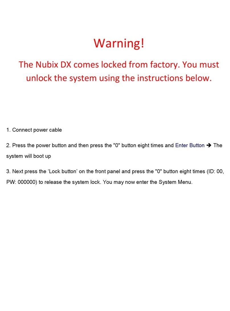
Eclipse Security Nubix DX User manual
