eco3energy PAW-TD20C1E5-UK User manual

1
PLEASE LEAVE THIS MANUAL WITH THE UNIT AFTER INSTALLATION
145963-06 04-2019
Installation Manual
PAW-TD20/30C1E5-UK
PAW-TD20/30C1E5-UK-1
Thank-you for purchasing the PAW unvented hot water cylinder.
-
Guide.
-
Contents
Page no.
...........................2
.......... 4
3. Pipe connections ...............................4
............. 5
5. Draining and Flushing........................5
6. Electrical installation ..........................5
..........................9
.....................................10
... 11
10. Warranty ..........................................12
.......................................... 13
This cylinder is manufactured and approved in accordance with EN 12897 : 2006

2
1. General information
1.1 Health and Safety regulations
-
The PAW cylinder should be transported and stored in a vertical position.
1.2 Siting the PAW cylinder
-
1.3 Component Check list
•
• Tundish
•
•
•
1.4 Components factory tted
•
•
•
1.5 Documentation supplied
•
1.6 Supply requirements
pipe to the unit.
1.7 Expansion vessels
-
1.8 Compatible ttings and components
1.9 Non-compatible products.
unvented cylinders.
3
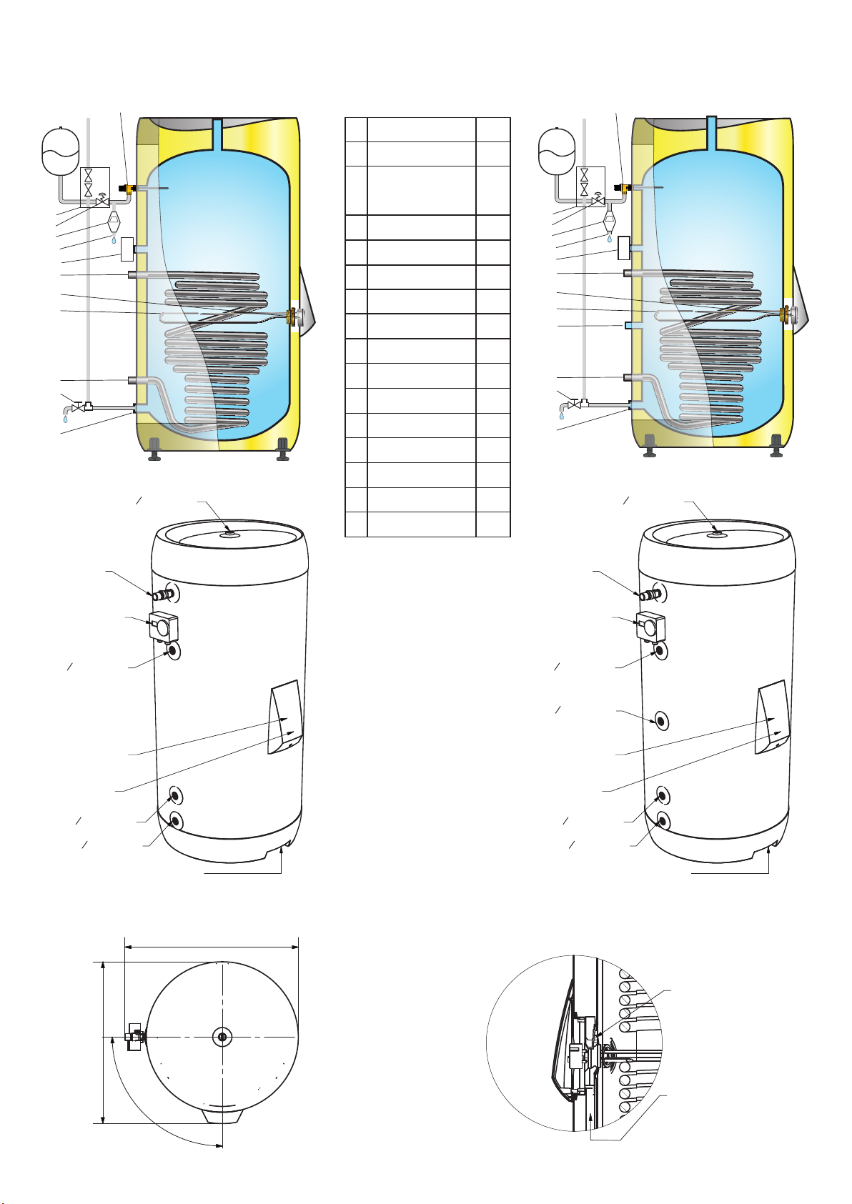
General Layout
Key
1
2
3
4
5-
92020
6 Tundish
7 71234
8
80314
9
80345
10 Cold Water Inlet
11
12
13 Discharge Pipe
14
15
16
1
6
5
4
3
2
7
16
8
15
13
9
1110
10
12
A-A
B ( 0,2 : 1 )
L-L ( 1:12 )
N ( 1 : 6 )
R ( 1 : 6 )
T ( 1 : 6 )
U ( 1 : 6 )
A
A
B
L
L
N
R
T
U
1
1
2
2
3
3
4
4
5
5
6
6
A A
B B
C C
D D
Format
Designed by:
Approved by:
Scale
Title Date:
A\S OSO, N - 3300 Hokksund Tlf: 32 25 00 00 Fax: 32 25 00 90
Drawing no. Rev
Drawing type:
This drawing is copyright and
shall not be reproduced or
disclosed to a third party without
express permission by OSO
Hotwater A\S Norway C
Projection
15.10.2018
Panasonic PAW-TD20C1E5-UK 1:12
2D
16-0703 03
A3
PB
All dimensions are specified in millimeters (mm) unless otherwise stated.
Tolerance based on ISO 2768-1 very coarse
266
866
1265 -3
10+
Return
34
" BSP female
Flow
34
" BSP female
CW inlet
34
" BSP female
155
0
595Ø
1,5kW 1x230V
365
90°
Power supply/
Thermistor cable
inlet
Va cuumIn s ul at ed
Pa nels ( V IP)
1.8m²
Ø22mm
Vacuum
Insulated
Panel
(VIP)
492Ø
1087
P&T valve 1/2"
HW outlet
34
" BSP female
Thermistor housing
Power supply/
Thermistor cable
duct
Immersion Heater w/
Thermostat & Safety
Cut-out
Housing for
Thermistor probe
Power supply and Thermistor cable inlet
679
640
Cylinder Thermostat
w/Safety Cut-Out
and Sensor pocket
HWC
34
" BSP female
A-A
B ( 0,2 : 1 )
L-L ( 1:12 )
N ( 1 : 6 )
R ( 1 : 6 )
T ( 1 : 6 )
U ( 1 : 6 )
A
A
B
L
L
N
R
T
U
1
1
2
2
3
3
4
4
5
5
6
6
A A
B B
C C
D D
Format
Designed by:
Approved by:
Scale
Title Date:
A\S OSO, N - 3300 Hokksund Tlf: 32 25 00 00 Fax: 32 25 00 90
Drawing no. Rev
Drawing type:
This drawing is copyright and
shall not be reproduced or
disclosed to a third party without
express permission by OSO
Hotwater A\S Norway C
Projection
15.10.2018
Panasonic PAW-TD20C1E5-UK 1:12
2D
16-0703 03
A3
PB
All dimensions are specified in millimeters (mm) unless otherwise stated.
Tolerance based on ISO 2768-1 very coarse
266
866
1265 -3
10+
Return
34
" BSP female
Flow
34
" BSP female
CW inlet
34
" BSP female
155
0
595Ø
1,5kW 1x230V
365
90°
Power supply/
Thermistor cable
inlet
V acu um Ins ul at ed
P ane ls( VIP )
1.8m²
Ø22mm
Vacuum
Insulated
Panel
(VIP)
492Ø
1087
P&T valve 1/2"
HW outlet
34
" BSP female
Thermistor housing
Power supply/
Thermistor cable
duct
Immersion Heater w/
Thermostat & Safety
Cut-out
Housing for
Thermistor probe
Power supply and Thermistor cable inlet
679
640
Cylinder Thermostat
w/Safety Cut-Out
and Sensor pocket
HWC
34
" BSP female
A-A
B ( 0,2 : 1 )
L-L ( 1:12 )
N ( 1 : 6 )
R ( 1 : 6 )
T ( 1 : 6 )
U ( 1 : 6 )
A
A
B
L
L
N
R
T
U
1
1
2
2
3
3
4
4
5
5
6
6
A A
B B
C C
D D
Format
Designed by:
Approved by:
Scale
Title Date:
A\S OSO, N - 3300 Hokksund Tlf: 32 25 00 00 Fax: 32 25 00 90
Drawing no. Rev
Drawing type:
This drawing is copyright and
shall not be reproduced or
disclosed to a third party without
express permission by OSO
Hotwater A\S Norway C
Projection
13.04.2018
Panasonic PAW-TD20C1E5-UK 1:12
2D
16-0703 02
A3
PB
All dimensions are specified in millimeters (mm) unless otherwise stated.
Tolerance based on ISO 2768-1 very coarse
266
866
1265 -3
1 0+
Return 34" BSP female
Flow 34" BSP female
CW inlet 34" BSP female
155
0
595
Ø
1,5kW 1x230V
365
90°
Power supply/
Thermistor cable
inlet
V a cu u m I n s ul at ed
P ane ls ( V IP)
1.8m²
Ø22mm
Vacuum
Insulated
Panel
(VIP)
492Ø
1087
P&T valve 1/2"
966
HWC
34" BSP female
HW outlet 34" BSP female
Thermistor housing
Power supply/
Thermistor cable
duct
Cylinder Thermostat
w/Safety Cut-Out
and Sensor pocket
Immersion Heater w/
Thermostat & Safety
Cut-out
Housing for
Thermistor probe
Power supply and Thermistor cable inlet
679
640
1
6
5
4
3
2
7
9
8
15
13
1110
10
12
PAW-TD..C1E5-UK PAW-TD..C1E5-UK-1
A-A
B ( 0,2 : 1 )
L-L ( 1:12 )
N ( 1 : 6 )
R ( 1 : 6 )
T ( 1 : 6 )
U ( 1 : 6 )
A
A
B
L
L
N
R
T
U
1
1
2
2
3
3
4
4
5
5
6
6
A A
B B
C C
D D
Format
Designed by:
Approved by:
Scale
Title Date:
A\S OSO, N - 3300 Hokksund Tlf: 32 25 00 00 Fax: 32 25 00 90
Drawing no. Rev
Drawing type:
This drawing is copyright and
shall not be reproduced or
disclosed to a third party without
express permission by OSO
Hotwater A\S Norway C
Projection
15.10.2018
Panasonic PAW-TD20C1E5-UK 1:12
2D
16-0703 03
A3
PB
All dimensions are specified in millimeters (mm) unless otherwise stated.
Tolerance based on ISO 2768-1 very coarse
266
866
1265 -3
10+
Return
34
" BSP female
Flow
34
" BSP female
CW inlet
34
" BSP female
155
0
595Ø
1,5kW 1x230V
365
90°
Power supply/
Thermistor cable
inlet
Vacu u mIns ul at ed
Pane ls ( VIP )
1.8m²
Ø22mm
Vacuum
Insulated
Panel
(VIP)
492Ø
1087
P&T valve 1/2"
HW outlet
34
" BSP female
Thermistor housing
Power supply/
Thermistor cable
duct
Immersion Heater w/
Thermostat & Safety
Cut-out
Housing for
Thermistor probe
Power supply and Thermistor cable inlet
679
640
Cylinder Thermostat
w/Safety Cut-Out
and Sensor pocket
HWC
34
" BSP female

4
3. Pipe Connections
2. Preparation of installation area
2.1 Positioning the unit
water heater.
2.2 Protection from frost
-
3.1 Cold water supply
3.1.2-
terrupted supply.
3.1.3
3.1.4
3.1.5-
3.1.6
3.1.7
together in a Tee as shown on page 3.
3.1.8
3.1.9
3.1.10
3.2 Hot water supply
3.3 Balanced cold water supply (optional).
-
3.4 Secondary return (optional)
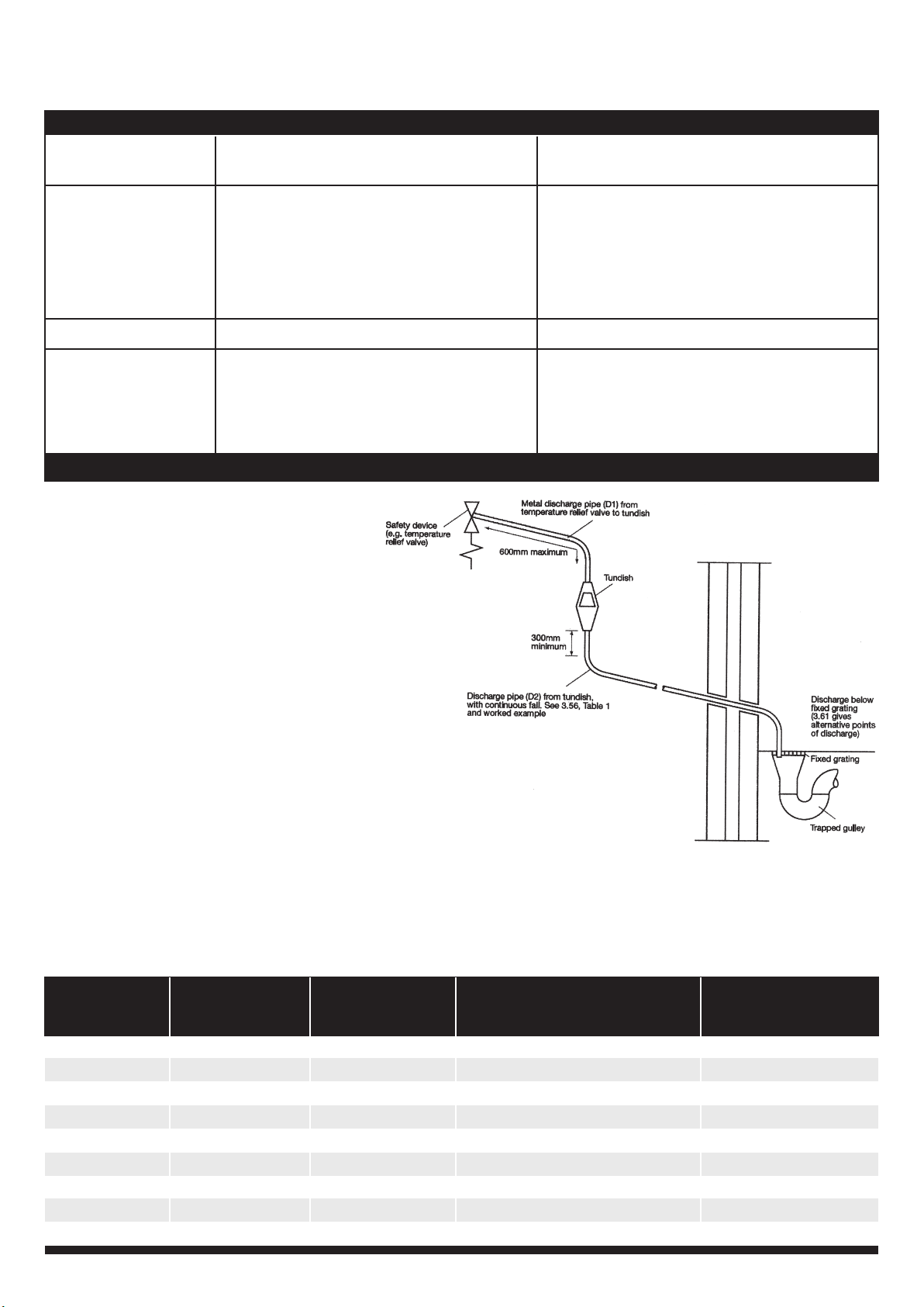
3.5 Discharge pipe

5
4. Commissioning and lling up
5. Draining & ushing out the system
4.1 Commissioning
4.1.1
4.1.2
4.1.3
pipe.
5.1 Draining
5.2 System ushing
3.6 Primary Flow and Return and Motorised valve
3.6.1
3.6.2
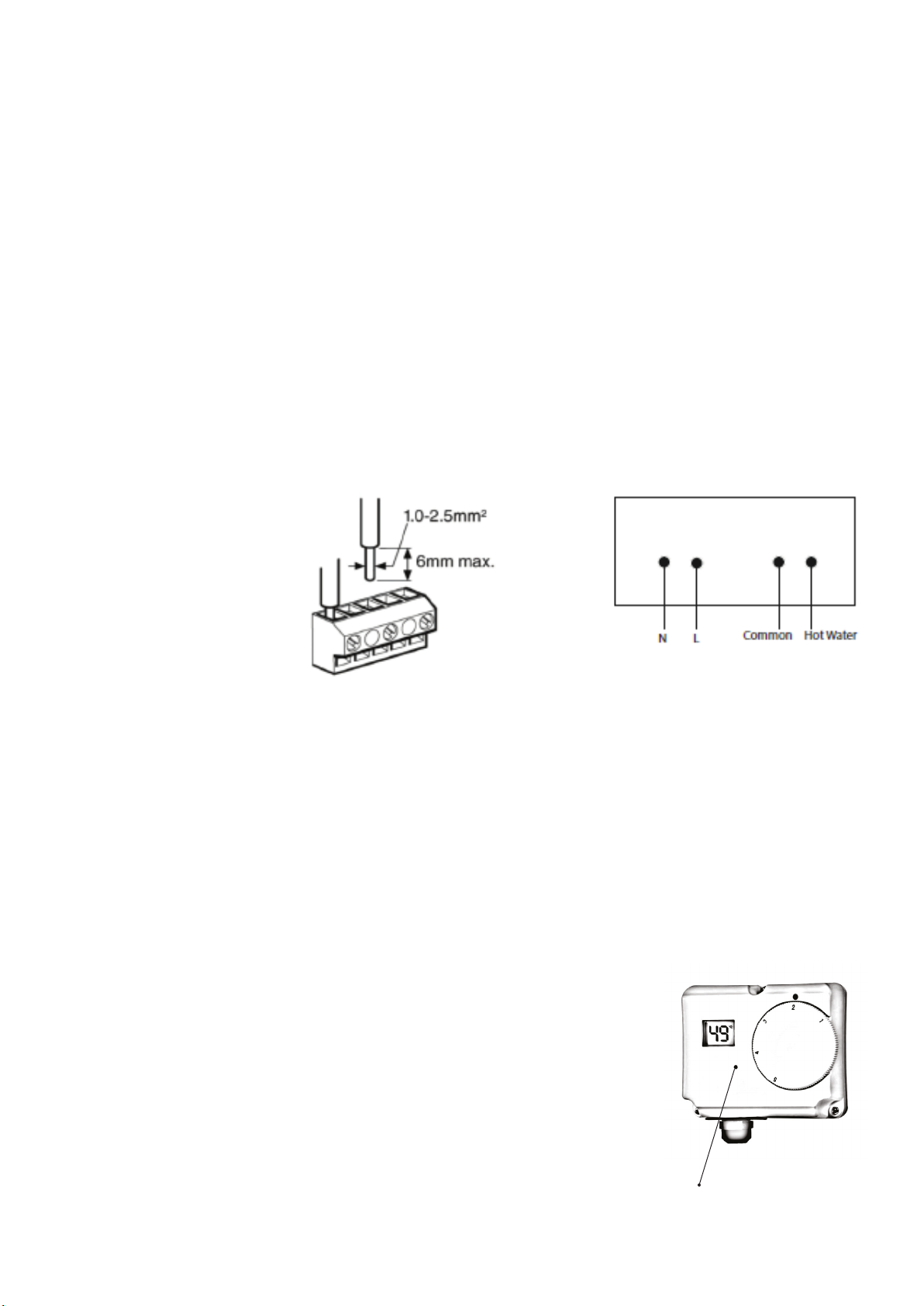
6. Electrical installation - all wiring must conform to current IEE regulations
6.1 Immersion heater Thermostat
-
OSO Hotwater AS can not be held
responsible if alternative wiring plans are used.
Important: Before resetting the safety cut-out or
altering the thermostat setting isolate electrical
supply to the unit before removal of the lid.
Ensure the lid to the electrical box is replaced.
6
6.2 Motorised valve
6.4 Digital Dual Cylinder Thermostat
-
-
-
-
-
pressed in.
Wiring Diagram
-
ing page 7 and 8.
supply.
6.4.1 Holiday Mode
-
OSO Hotwater AS can not be responsible if alternative wiring plans are used. Important: Before resetting the safety cut-out
or altering the thermostat setting isolate electrical supply to the unit before removal of the lid.
6.4.1 Adjusting the 1 Hour Boost
7
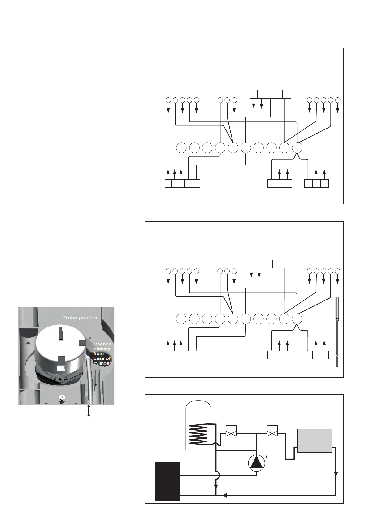
S-plan Wiring
PAW cylinders
Thermistor controlled Heat
Pumps/Boilers
attach to the cylinder.
to secure the sensor on the
PAW cylinder. The
the additional cylinder
Channel running
Pump
flow
2-port valve
(supplied)
Zone valve
(not supplied)
Automatic
bypass
Radiators/
UFH
HP/Boiler
Piping
Diagram
Zone Valve (DHW)
(supplied)
12
231
T6360B
357
3
G/Y
LNE 4
G Br Bl O
L NE L NE
Pump
1 2 323 23
22 31
V4043H
Cylinder
Thermostat
(supplied) Wired as
high limit stat
Isolated Mains
Supply From
Fused Spur
Zone Valve (Htg)
(not supplied)
Room
thermostat
L NE
69
2 31
V4043H
G B r B1 O
G/Y
4 8 10
Wiring for Thermistor Controlled Heat Pump
1 2
Thermistor
Thermistor wire
Connected to
Heat Pump control
system
12
231
T6360B
357
3
G/Y
LNE 4
G Br Bl O
L NE L NE
Heat Pump Pump
1 2 323 23
22 31
V4043H
Cylinder
Thermostat
(supplied)
Isolated Mains
Supply From
Fused Spur
Zone Valve (Htg)
(not supplied)
Room
thermostat
L N E
69
2 31
V4043H
G Br B1 O
G/Y
4 8 10
Wiring for Standard Heat pump
1 2
Zone Valve (DHW)
(supplied)
N
L
CNC NO
N
L
CNC NO
ST6400
Programmer
HW
ON
HTG
ON
ST6400
Programmer
HW
ON
HTG
ON Heat pump differential controler

8
Y-plan Wiring
Thermistor controlled Heat
Pumps/Boilers
attach to the cylinder.
to secure the sensor on the
PAW cylinder. The
Channel running
12
E
231
T6360B
3
3 14
G O B1 Br
G/Y
NL E NL E NL
ST6400
Heat pump Pump
1 2 332 32
2 2 3
1
V4043H
Room
thermostat
Zone Valve (DHW)
(supplied)
Isolated Mains
Supply From
Fused Spur
Mid Position Valve
(not supplied)
L N E
6
G/Y
B1 W Gr O
3 2
V4073A1039
104 5 987
Cylinder Thermostat (supplied)
N
L
C NC NO
Thermistor
12
E
231
T6360B
3
3 14
G O B1 Br
G/Y
NL E NL ENL
ST6400 Heat pump differential controler Pump
1 2 332 32
2
23
1
V4043H
Room
thermostat
Zone Valve (DHW)
(supplied)
Isolated Mains
Supply From
Fused Spur
Mid Position Valve
(not supplied)
L N E
6
G/Y
B1 W Gr O
3 2
V4073A1039
104 5 987
Cylinder Thermostat (supplied )
wired as high limit Stat
N
L
C NC NO
Thermistor wire
Connected to
Heat pump control
system
Pump
flow
2-port valve
(supplied)
Mid pos. valve
(not supplied)
Radiators/
UFH
HP/Boiler
Automatic
bypass
Piping
Diagram
HW
ON
HW
OFF
HTG
ON
HW
ON
HW
OFF
HTG
ON
Programmer
Programmer
Wiring for Standard Heat pump
Wiring for Thermistor Controlled Heat Pump

9
7. Safety and servicing
7.1 Safety Cut-out
1. Wiring is incorrect.
2.
3.
4.
5.
6.
7. 2 Intermittent or slow discharge from tundish
1.
2.
3.
4.
seconds.
5.
6.
7.
8.
9.
7.3 Continuous very hot water discharge from tundish
7.4 Expansion vessel maintenance
-
value.
7.5 Guarantee
7.6 Servicing Procedure:
7.6.1 Expansion relief valve
7.6.2 Pressure reducing valve
7.6.3 Expansion relief cartridge
Do not overtighten.
7.6.4 Temperature and Pressure relief valve
7.6.5 Internal inspection
10
8. Fault Finding Guide
Alternative Discharge
dedicated to the unvented cylinder. The pipe
-
Important - note:
FAULT POSSIBLE CAUSE SOLUTION
No water ow from hot taps.
Water from hot taps is cold.
Intermittent water discharge.
Continous water discharge.
Minimum size of Maximum resistance allowed,
Minimum size of discharge pipe D2* expressed as a lenght of straight Resistance created by
Valve outlet size discharge pipe D1* from tundish pipe (i.e. no elbows or bends) each elbow or bend

11
Technical data
M.T. ITEM No. MODEL/IDENTIFIER Rating ErP Heat loss - W Storage vol.
80341850
A 43 192
80341950
A 49 284
Description Unit PAW-
TD20C1E5-UK PAW-
TD30C1E5-UK PAW-
TD20C1E5-UK-1 PAW-
TD30C1E5-UK-1
192 284 192 284
595 595 595 595
1270 1750 1270 1750
50 61 50 61
241 341 241 341
-
incoloy 825 incoloy 825 incoloy 825 incoloy 825
-
50 50 50 50
-
21 21 21 21
1.01 1.15 1.03 1.18
Watts
42 48 43 49
315 465 315 465
l/h
900 900 900 900
18.5 26.08 18.5 26.08
35 32 35 32
120 120 120 120
255 464 255 464
ErP class
-
A A A A
1 / 10 1 / 10 1 / 10 1 / 10
1 / 10 1 / 10 1 / 10 1 / 10
0.3 / 3 0.3 / 3 0.3 / 3 0.3 / 3
0.25 / 2.5 0.25 / 2.5 0.25 / 2.5 0.25 / 2.5
°C
70 70 70 70
°C 99
99
99
99
Secondary return
Inch
Inch
Inch
Cold water
Inch
Inch
Inch
Inch
8 8 8 8
Electrical characteristics
Electrical installation
-
IEEE regs IEEE regs IEEE regs IEEE regs
-
Phase
single single single single
°C
8-70 18-70 8-70 18-70
°C
60 60 60 60
0.8 / 8 0.8 / 8 0.8 / 8 0.8 / 8
°C
87 87 87 87
°C
80 80 80 80

12
1. Scope
-
shall apply.
2. Coverage
-
3. Conditions
•
•
•
•
•
•
•
•
•
• -
•
•
4. Limitations
•
•
•
•
•
•
Warranty

13
The code of practice for the installation,
commissioning & servicing of mains pressure hot water storage
Installation,Commissioning
and Service Record Log Book
CUSTOMER DETAILS
NAME
ADDRESS
TEL No.
IMPORTANT
The above does not aect your statutory rights.
INSTALLER & COMMISSIONING ENGINEER DETAILS
INSTALLER DETAILS
COMPANY NAME DATE
ADDRESS
INSTALLER NAME TEL No.
REGISTERED OPERATIVE ID CARD No.
(IF APPLICABLE)
REGISTRATION DETAILS
COMMISSIONING ENGINEER (IF DIFFERENT)
NAME DATE
ADDRESS
TEL No.
REGISTERED OPERATIVE ID CARD No.
(IF APPLICABLE)
REGISTRATION DETAILS
IT IS THE RESPONSIBILITY OF THE INSTALLER TO COMPLETE THIS LOGBOOK AND PASS IT
ON TO THE CUSTOMER. FAILURE TO DO SO MAY INVALIDATE THE CYLINDER GUARANTEE

14
APPLIANCE & TIME CONTROL DETAILS
MANUFACTURER MODEL
CAPACITY
TYPE
TIME CONTROL
UNVENTED
PROGRAMMER
litres SERIAL No.
TIME SWITCH
or
COMMISSIONING PROCEDURE INFORMATION
BOILER PRIMARY SETTINGS (INDIRECT HEATING ONLY) ALL BOILERS
IS THE PRIMARY A SEALED OR OPEN VENTED SYSTEM? SEALED OPEN
WHAT IS THE INDIRECT HEAT SOURCE FLOW TEMPERATURE? C
ALL MAINS PRESSURISED SYSTEMS
YES
WHAT IS INCOMING STATIC COLD WATER PRESSURE AT THE INLET TO THE
PRESSURE REDUCING VALVE?
HAS STRAINER (IF FITTED) BEEN CLEANED OF INSTALLATION DEBRIS?
HAS A WATER SCALE REDUCER BEEN FITTED?
WHAT TYPE OF SCALE REDUCER HAS BEEN FITTED?
NO
YES NO
UNVENTED SYSTEMS
YES
ARE COMBINED TEMPERATURE AND PRESSURE RELIEF VALVE
AND EXPANSION VALVE FITTED AND DISCHARGE TESTED?
IS PRIMARY ENERGY SOURCE CUT OUT FITTED
(NORMALLY 2 PORT VALVE)?
WHAT IS THE PRESSURE REDUCING VALVE SETTING (IF FITTED)?
WHERE IS OPERATING PRESSURE REDUCING VALVE SITUATED?
NO
YES NO
bar
HAS THE EXPANSION VESSEL OR INTERNAL AIR SPACE BEEN CHECKED? YES NO
WHAT IS THE HOT WATER TEMPERATURE AT THE NEAREST OUTLET? C
bar
ALL PRODUCTS
YES
DOES THE HOT WATER SYSTEM COMPLY WITH
THE APPROPRIATE BUILDING REGULATIONS?
HAS THE SYSTEM BEEN INSTALLED AND COMMISSIONED
IN ACCORDANCE WITH THE MANUFACTURER’S INSTRUCTIONS?
HAVE YOU DEMONSTRATED THE OPERATION OF THE
SYSTEM CONTROLS TO THE CUSTOMER? YES
YES
HAVE YOU LEFT ALL THE MANUFACTURER’S
LITERATURE WITH THE CUSTOMER? YES
COMPETENT PERSON’S
SIGNATURE
CUSTOMER’S
SIGNATURE
(To conrm demonstrations of equipment and
receipt of appliance instructions)
PLEASE FOLLOW THE INSTALLATION AND COMMISSIONING INSTRUCTIONS
IN THE INSTALLATION MANUAL SUPPLIED WITH THE EQUIPMENT

15
SERVICE INTERVAL RECORD
SERVICE PROVIDER
ENGINEER NAME
SERVICE 1
COMPANY NAME
TEL No.
COMMENTS
SIGNATURE
DATE:
ENGINEER NAME
SERVICE 3
COMPANY NAME
TEL No.
COMMENTS
SIGNATURE
DATE:
ENGINEER NAME
SERVICE 5
COMPANY NAME
TEL No.
COMMENTS
SIGNATURE
DATE:
ENGINEER NAME
SERVICE 7
COMPANY NAME
TEL No.
COMMENTS
SIGNATURE
DATE:
ENGINEER NAME
SERVICE 9
COMPANY NAME
TEL No.
COMMENTS
SIGNATURE
DATE:
ENGINEER NAME
SERVICE 2
COMPANY NAME
TEL No.
COMMENTS
SIGNATURE
DATE:
ENGINEER NAME
SERVICE 4
COMPANY NAME
TEL No.
COMMENTS
SIGNATURE
DATE:
ENGINEER NAME
SERVICE 6
COMPANY NAME
TEL No.
COMMENTS
SIGNATURE
DATE:
ENGINEER NAME
SERVICE 8
COMPANY NAME
TEL No.
COMMENTS
SIGNATURE
DATE:
ENGINEER NAME
SERVICE 10
COMPANY NAME
TEL No.
COMMENTS
SIGNATURE
DATE:
HWSLB First Edition 01.03.02

16
This manual suits for next models
3
Table of contents


