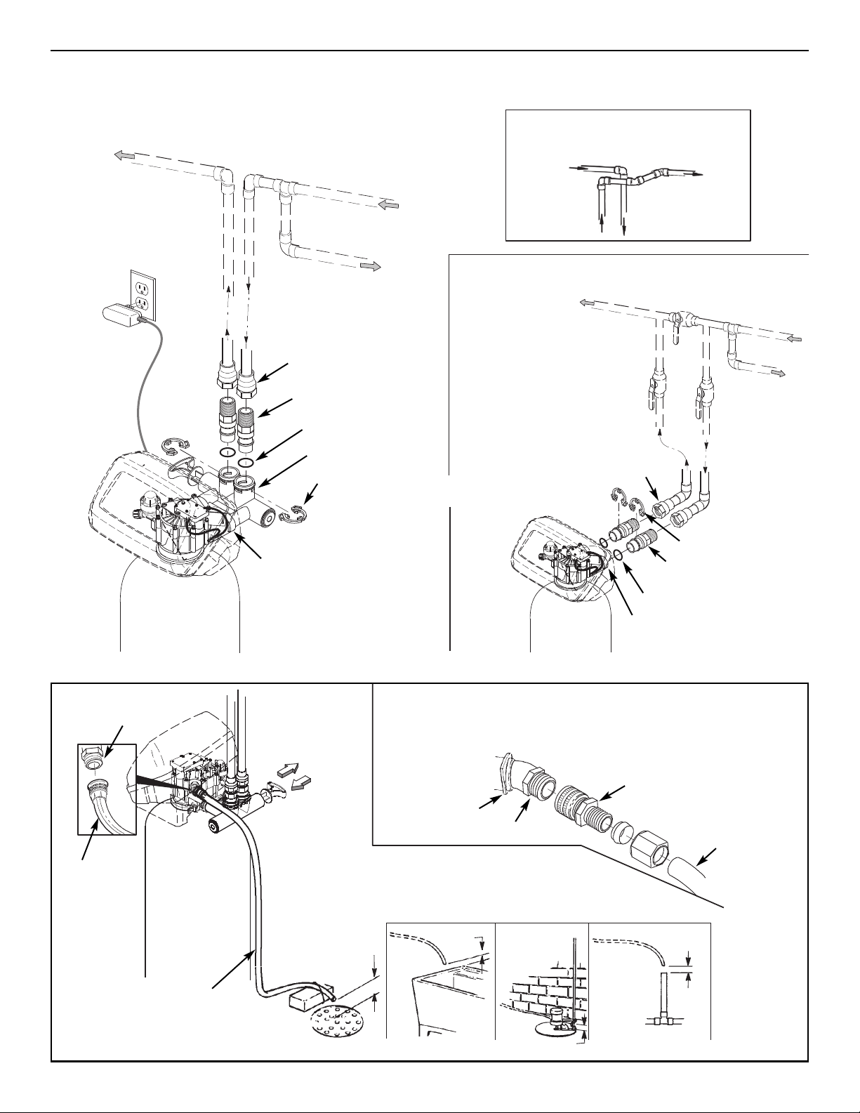
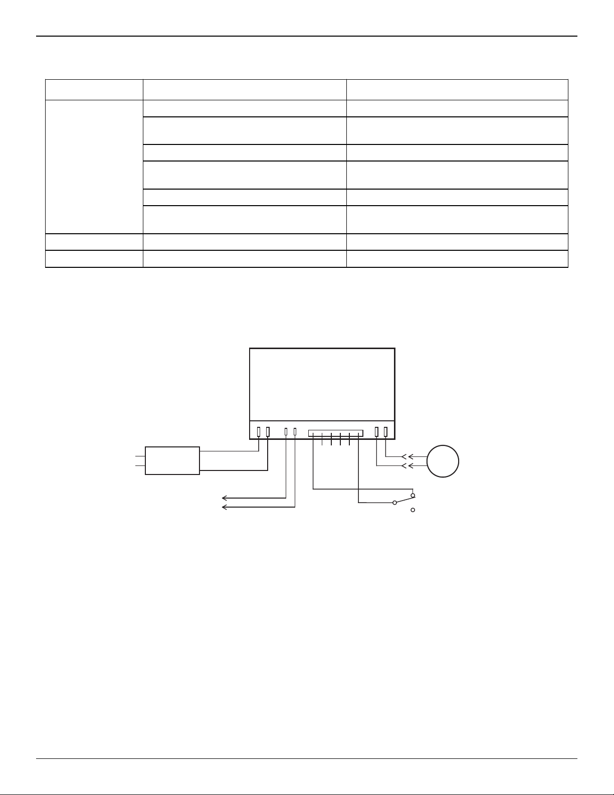
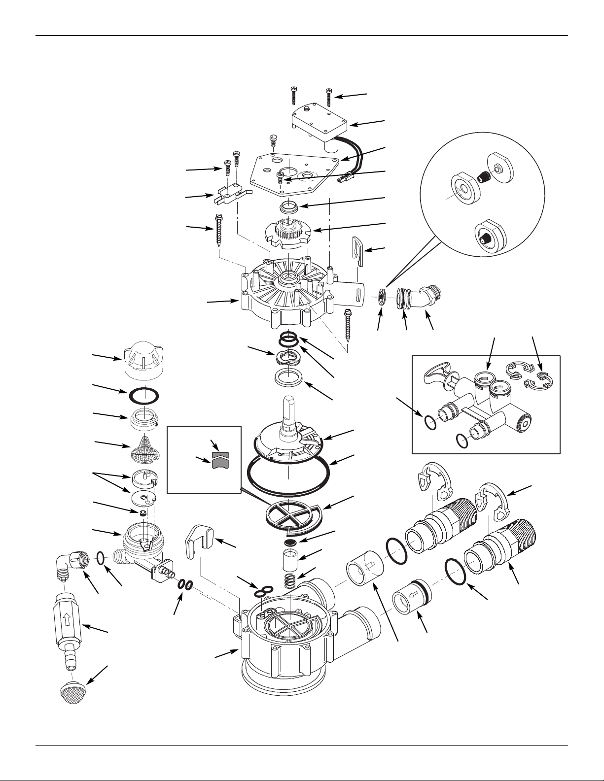
Ecodyne Water Systems OH2-Iron Use and care manual

7344510 (Rev. 6/28/16)
Models
NSAIV-10, NSAIV-12 & NS IV-10
“OH2-Iron”
Air Aspirated Chemical-Free Iron Filter
Installation
Operation
Maintenance
Repair Parts
Manufactured and warranted by
codyne Water Systems
1890 Woodlane Drive
Woodbury, MN 55125
Designed, Engineered &
Assembled in the U.S.A.
NSAIV-10 and NSAIV-12 are tested and certified
by the Water Quality Association against
NSF/ANSI Standard 372 for low lead content.
NS IV-10 tested and certified without media
by the Water Quality Association against
NSF/ANSI Standard 372 for low lead content.

2
TABLE OF CO TE TS
Page
Inspect Shipment . . . . . . . . . . . . . . . . . . . . . . . . . 2
Safety Guides . . . . . . . . . . . . . . . . . . . . . . . . . . . . 2
Specifications & Dimensions . . . . . . . . . . . . . . . . . 3
Before Starting Installation . . . . . . . . . . . . . . . . . . 4
Media Loading (Model NSEIV-10) . . . . . . . . . . . . .5
Typical Installation Illustrations . . . . . . . . . . . . . . . 6
Installation Instructions . . . . . . . . . . . . . . . . . . . 7-8
Sanitizing Procedure . . . . . . . . . . . . . . . . . . . . . . . 9
Programming the Electronic Controller . . . . . 10-11
Controller eatures / Options . . . . . . . . . . . . . 11-13
Routine Maintenance . . . . . . . . . . . . . . . . . . . . . 13
Troubleshooting . . . . . . . . . . . . . . . . . . . . . . . 14-16
Wiring Schematic . . . . . . . . . . . . . . . . . . . . . . . . 16
Exploded View & Parts List . . . . . . . . . . . . . . 17-19
Warranty . . . . . . . . . . . . . . . . . . . . . . . . . . . . . . . .20
Recommended maximum allowable inlet water
pressure is 80 psi. Use a pressure reducing valve if
necessary. Be sure the addition of a pressure reduc-
ing valve will not reduce the flow to less than the 5
gallons per minute needed for backwash.
The filter works on 28V DC electrical power, supplied
by a direct plug-in power supply (included). Be sure
to use the included power supply, and plug it into a
nominal 120V, 60 Hz household outlet that is in a dry
location only, grounded and properly protected by
an overcurrent device such as circuit breaker or fuse.
This system is not intended to be used for treating
water that is microbiologically unsafe or of unknown
quality without adequate disinfection before or after
the system.
European Directive 2002/96/EC requires all
electrical and electronic equipment to be
disposed of according to Waste Electrical
and Electronic Equipment (WEEE) require-
ments. This directive or similar laws are in
place nationally and can vary from region to
region. Please refer to your state and local
laws for proper disposal of this equipment.
Safety Guides
ollow the installation instructions carefully. ailure to
install the filter properly voids the warranty.
Before you begin installation, read this entire manual.
Then obtain all the materials and tools you will need
to make the installation.
Check local plumbing and electrical codes. The
installation must conform to them.
Use only lead-free solder and flux for all sweat-sol-
der connections as required by state and federal
codes.
Use care when handling the filter. Do not turn upside
down, drop, or set on sharp protrusions.
Do not locate the filter where freezing temperatures
occur. Do not attempt to filter water over 120°F.
reezing, or hot water damage voids the warranty.
Avoid installing in direct sunlight. Excessive sun heat
may cause distortion or other damage to non-metallic
parts.
The filter requires a minimum water flow of 5 gallons
per minute at the inlet for backwash.
Inspect S ipment
The parts required to assemble and install the Air
Aspirated Iron ilter are included with the unit.
Thoroughly check the water filter for possible shipping
damage and parts loss. Also inspect and note any
damage to the shipping carton.
Remove and discard (or recycle) all packing materi-
als. To avoid loss of small parts, we suggest you
keep the small parts in the parts bag until you are
ready to use them.
Packing List
Ground Clamp
Kit
Clips
FIG. 1
Bypass Valve
Installation
Adaptors
O-rings

INLET -
OUTLET
3-3/4"
14"
OUTLET
INLET
A C
B
3
SAIV-10
SEIV-10 SAIV-12
Nominal Mineral
Tank Size
10” dia. x
47” tall
12” dia. x
54” tall
A58-1/8” 64-1/4”
B49-3/4” 55-1/2”
C10-1/2” 12-1/4”
Dimensions
FIG. 2
Specifications
14”
3-3/4”
A
B
C
INLET
OUTLET
INLET-
OUTLET
Model SAIV-10 Model SAIV-12 Model SEIV-10
Model Code HAAI HAAI HAAI
Amount of Zeolite Media 1.0 cu. ft. 2.0 cu. ft. –
Amount of Quartz Gravel 17 lbs 29 lbs. 17 lbs
low Rate 7 - 10 gpm 9 - 15 gpm 7 - 10 gpm
Minimum Backwash low Rate 7 gpm* 10 gpm* 7 gpm***
Maximum Supply Water Pressure 80 psi
Water Temperature Limits (min./max.) 40 - 120 °
Electrical Requirements 120V, 60 Hz (28V DC, 350 mA power supply included)
Contaminant Removal Limitations Up to 10 ppm iron (except bacterial
and organically bound iron**)
Consult media specifications
for contaminant limitations
*Well pump must be able to provide the minimum flow for 30+ minutes.
**Consult manufacturer for applications with bacterial or organically bound iron.
***Install a backwash flow control that is appropriately sized for the media used.

4
Before Starting Installation
WHERE TO I STALL THE FILTER
=Place the filter as close as possible to the pressure
tank (well system) or water meter (city water).
=Place the filter as close as possible to a floor
drain, or other acceptable drain point (laundry tub,
sump, standpipe, etc.). CAUTIO : Drain water
exits the hose at a fast flow rate, and at water sys-
tem pressure. Be sure the hose is fastened in
some manner to prevent ”whipping” and splashing
to prevent water damage to surrounding area.
=Connect the filter to the main water supply pipe
UPSTREAM O the water heater. DO NOT RUN
HOT WATER THROUGH THE ILTER. The tem-
perature of water passing through the filter must
be less than 120° .
=Keep outside faucets on unfiltered water to con-
serve filtering capacity.
=Do not install the filter in a place where it could
freeze. Damage caused by freezing is not cov-
ered by the warranty.
=Put the filter in a place water damage is least likely
to occur if a leak develops. The manufacturer will
not repair or pay for water damage.
=A 120V, 60 Hz electrical outlet, to plug the included
power supply into, is needed near the filter. Be
sure the electrical outlet and power supply are in
an inside location, to protect from wet weather.
=If installing in an outside location, you must take
the steps necessary to assure the filter, installation
plumbing, wiring, etc., are as well protected from
the elements, contamination, vandalism, etc., as
when installed indoors.
=Keep the filter out of direct sunlight. The sun's heat
may soften and distort plastic parts.
TOOLS, PIPE & FITTI GS,
OTHER MATERIALS YOU WILL EED
=Plastic inlet and outlet fittings included with the fil-
ter allow water flow equivalent to 1 inch nominal
pipe. To maintain full valve flow, 1” pipes to and
from the filter fittings are recommended. Do not
reduce the pipes to less than 3/4” size.
=Use copper, brass or PEX plastic pipe and fittings.
=ALWAYS install the included check valve on the
INLET pipe, immediately upstream of the filter.
=ALWAYS install the included bypass valve, or 3
shut-off valves. Bypass valves let you turn off
water to the filter for repairs if needed, but still
have water available to the house pipes.
=Drain hose 5/8” inside diameter minimum, with a
garden hose connection on one end, is needed for
the valve drain. See step 5 on page 8.
=If a rigid valve drain is needed, to comply with
plumbing codes, you can buy the parts needed
(see page 6) to connect a 5/8” minimum copper
tubing drain.
PLA HOW YOU WILL I STALL THE FILTER
You must first decide how to run in and out pipes to
the filter. Look at the house main water pipe at the
point where you will connect the filter. Is the pipe sol-
dered copper, glued plastic, or threaded brass/galva-
nized? What is the pipe size?
Now look at the typical installation illustration on page
6. Use it as a guide when planning your particular
installation. Be sure to direct incoming, unfiltered
water to the filter valve inlet fitting. The valve ports
are marked IN and OUT.

5
Media Loading (Model NSEIV-10)
MEDIA LOADI G
Model SEIV-10, as manufactured, has no media
other than quartz gravel at the bottom of the tank
(See table on Page 3 for amount). Before plumbing
this unit, load media:
1. Move the filter into installation location and set it on
a flat, level surface. If a twin installation, keep
tanks separated for ease of service.
2. Take off the unit’s top cover and unplug the wiring
connections between the valve and the control
board (PWA).
3. Remove retainer clips and clamp sections from the
tank neck and carefully lift the valve off the tank.
4. Check the height of the riser pipe as shown in
igure 3. If riser pipe is more than 1/2” above the
top distributor, make sure that bottom distributor is
below gravel at the bottom of the tank. It may be
necessary to lay the filter on its side to move gravel
to one side, hold the bottom distributor at the bot-
tom center of the tank and stand the unit back up.
Level gravel after checking.
5. After confirming the riser pipe height, remove the
top distributor from the tank neck, leaving the bot-
tom distributor (including riser pipe) in place, cen-
tered in the tank.
6. Cover the top end of the riser pipe with a clean
rag, to keep media out (See ig. 4).
7. Using a larger neck funnel, add the necessary
amount of media.
8. lush the tank opening with water to clean media
particles from the top of the tank. Uncover the bot-
tom distributor stand tube.
9. ill the tank with water, up to the top of the tank.
IMPORTA T: Be sure to fill with water. This will elim-
inate air space, wet the media and pre-
vent excessive air-head pressure when
filter is pressurized.
10. Install the o-ring seals and top distributor exactly
as shown in igure 5. Place the small o-ring at
the top of the riser pipe, where shown in igure 3.
If the o-rings need lubrication, use a high quality
silicone grease.
11. Lower the valve assembly onto the tank, centering
over the riser tube. Push downward, against the
o-ring, and install the clamp sections, securing
with the retainer clips.
12. Verify that the backwash flow plug (See Key No. 59
on Page 18) is appropriately sized for the media
used. If necessary, install a different flow plug.
FIG. 4
unnel
Plug or cover top of
riser pipe
Tank
Make sure
bottom distributor
is centered
FIG. 5
Top
Distributor
Bottom
Distributor
Riser Pipe
O-Ring, 2-7/8” x 3-1/4”
Make sure o-ring
sealing surfaces
are clean
O-Ring, 13/16” x 1-1/16”
O-Ring, 2-3/4” x 3”
Top Edge of
Top Distributor
Riser Pipe
0” to 1/2”
ote: Resin tank height can vary somewhat within manu-
facturing tolerance. So that the bottom distributor riser pipe
has proper clearance with inside valve porting, check for
the correct length, as shown above. Cut the riser pipe if
needed to adjust the length. Be sure to remove burrs and
sharp edges.
FIG. 3

6
Typical Installation Illustrations
FIG. 8
Drain
itting
Valve
Drain
Hose
Valve
Drain
Hose
1-1/2”
Air Gap
1-1/2”
Air Gap
1-1/2””
Air Gap
1-1/2” Air Gap
LAU DRY
TUB
SUMP
STA D
PIPE
FLOOR
DRAI
To standpipe, sump, laundry
tub or other suitable drain.
5/8” I.D.
(minimum)
copper tube
Push in for
Bypass Clip
Drain itting
CO ECTI G A RIGID VALVE DRAI TUBE
To adapt a copper tube to the filter, buy a compression fitting (garden hose thread to
5/8” I.D. minimum tube and necessary tubing from your local hardware store.
Adaptor, garden hose
thread to compression
Pull out for
filtered water
“Service”
FIG. 7FIG. 6
I STALLATIO USI G 3-VALVE BYPASS
MAIN WATER PIPE
MAIN WATER PIPE
I STALLATIO USI G I CLUDED BYPASS VALVE CROSS-OVER
Use if water supply flows from the left.
Include single or 3-valve bypass.
iltered
Water OUT
Unfiltered
Water I
ILTERED
WATER
TO ILTER
INLET
UN ILTERED
WATER
ROM ILTER
OUTLET
BYPASS
Valve
OUTLET
Valve INLET
Valve
1” NPT
emale Adaptor (2)
not included
O-Ring Seal (2)*
1” NPT Installation
Adaptor (2)*
Valve
I LET
or filtered water SERVICE:
-Open the inlet and outlet
valves
or unfiltered BYPASS:
-Close the inlet and outlet
valves
-Open the bypass valve
Unfiltered Water
to Outside aucets
* Included with filter - Pipe and
fittings supplied by installer.
Valve
I LET
120V,
60 Hz
Outlet
Clip (2)*
Typical Installation Illustrations
1” NPT
emale Adaptor (2)
not included
1” NPT Installation
Adaptor (2)*
Bypass Valve*
Clip (4)*
O-Ring Seal (2)*

7
Installation
1. TUR OFF WATER SUPPLY
a. Close the main water supply valve near the well
pump or water meter.
b. Shut off the electric or fuel supply to the water
heater.
c. Open high and low faucets to drain all water from
the house pipes.
2. I STALL BYPASS VALVE A D/OR
PLASTIC I STALLATIO ADAPTORS:
a. If installing a single bypass valve, push the bypass
valve, with lubricated o-ring seals in place, into the
valve inlet and outlet ports (See igures 6 & 9).
- OR -
b. If installing a 3-valve bypass system, slide plastic
installation adaptors, with lubricated o-ring seals in
place, into the valve inlet and outlet ports (See
igures 7 & 9).
c. Be sure the check valve is in place in the valve
inlet, with the flow arrow pointed inward, as shown
in igure 9.
d. Be sure the turbine support is in place in the valve
outlet, as shown in igure 10.
e. Snap the two large plastic clips in place on the inlet
and outlet ports, from the top, down (See igure
11). Be sure they snap into place. Pull on the
bypass valve, or installation adaptors, to make sure
they are held securely in place.
3. COMPLETE PLUMBI G TO A D FROM
THE FILTER
Using the “Typical Installation Illustration” on page 6
as a guide, observe all of the following cautions while
you connect inlet and outlet plumbing:
=Be sure incoming, unfiltered water is directed to
the valve I LET port.
=Be sure to install the included check valve on
the I LET pipe, immediately upstream of the filter,
as shown in the “Typical Installation Illustration” on
page 6. Note the direction of the flow arrow on the
check valve.
=Be sure to install bypass valve(s).
=If making a soldered copper installation, do all
sweat soldering before connecting pipes to the fil-
ter fittings. Torch heat will damage plastic parts.
=Use pipe joint compound on all external pipe
threads.
=When turning threaded pipe fittings onto plastic fit-
tings, use care not to cross-thread.
=Support inlet and outlet plumbing in some manner
(use pipe hangers) to keep the weight off of the
valve fittings.
Turbine
Support
Valve
Outlet
FIG. 10
FIG. 11
O-ring Clip
Cross section of
valve inlet or outlet
Bypass valve or
plastic adaptor
Snap clips into place between
larger diameter rings
FIG. 12
Turn the bypass
valve downward if
connecting to floor
level plumbing
I LET
OUTLET
FIG. 9
I LET
OUTLET
Clip (2)
Turbine
Support
Plastic
Installation Adaptor
(install in filter valve
or bypass valve)
Bypass Valve
Clip (2)
Check Valve
(note direction
of flow arrow)

8
FIG. 13
Ground
Clamp
Inlet & Outlet
Pipes
Installation (continued)
b. Place bypass valve(s) into “bypass” position. On a
single valve, slide the stem inward to BYPASS
(See ig. 8 on page 6). On a 3 valve system,
close the inlet and outlet valves, and open the
bypass valve (See ig. 7 on page 6).
c. ully open the house main water pipe shutoff valve.
Observe a steady flow from both opened faucets.
d. Close both faucets.
e. Check your plumbing work for leaks and, if any are
found, fix right away. Be sure to observe previous
caution notes.
f. Turn on the gas or electric supply to the water
heater. Light the pilot, if applicable.
7. CO ECT TO ELECTRICAL POWER:
The filter controller works on 28V DC electrical power.
The included power supply converts 120V AC house-
hold power to 28V DC. Plug the power supply into a
120V, 60 Hz electrical outlet. Be sure the outlet is
always “live” so it can not be switched off by mistake.
8. PROGRAM THE CO TROLLER
See pages 10-11 for instructions to program the elec-
tronic controller.
9. START UP PROCEDURE
a. Confirm that the filter’s main valve is in the “service”
position (“S” on the cam).
b. Place bypass valve(s) into “service”, EXACTLY as
follows:
=Single Bypass Valve: SLOWLY, pull the valve
stem outward to ”service” position, pausing sev-
eral times to allow the filter to pressurize slowly.
=3 Valve Bypass: ully close the bypass valve
and open the outlet valve. SLOWLY, open the
inlet valve, pausing several times to allow the
filter to pressurize slowly.
c. Check all connections for leaks.
d. Push and hold the RECHARGE button until the fil-
ter starts a RECHARGE NOW cycle. Verify that
the valve advances to “backwash” (BW) position.
e. Allow the unit to remain in “backwash” (BW) while
air is purged and water exits the drain line. Ensure
that the drain line is secure and will withstand the
mix of air and water exiting.
f. Allow the unit to complete the 15 minute “backwash”
cycle and automatically advance to the “aspirate” (A)
position. Allow it to remain there as it aspirates air
into the mineral tank. After 75 minutes, the filter will
then automatically return to “service”. Start up is
complete.
4. I STALL GROU D CLAMP (IF EEDED):
If the home’s cold water piping is being used for elec-
trical grounding, a 3 valve bypass system maintains
ground continuity. If you are using a single plastic
bypass valve, install the included ground clamp, as
shown In igure 13, to maintain electrical ground conti-
nuity in the house cold water piping. Be sure the pipes
are clean, under the clamps, to assure good contact.
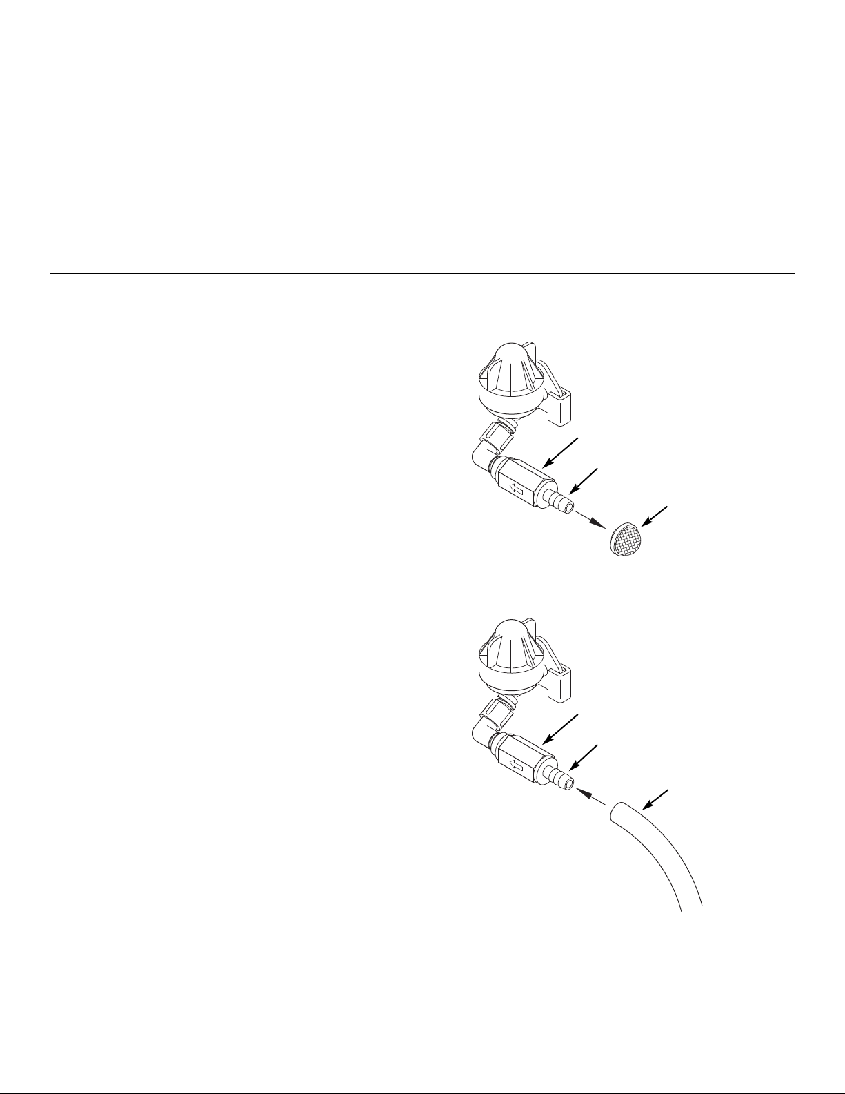
5. I STALL VALVE DRAI HOSE
a. Take a length of 5/8” inside diameter garden hose
and attach to the valve drain fitting (See igure 8
on page 6).
b. Locate the other end of the hose at a suitable drain
point (floor drain, sump, laundry tub, etc.). Check
and comply with local codes. Refer to igure 8 on
page 6 if codes require a rigid pipe drain run.
IMPORTA T: Use high quality, thick wall hose that
will not easily kink or collapse. The fil-
ter will not backwash properly if water
cannot exit this hose during recharges.
c. Tie or wire the hose in place at the drain point.
Water pressure will cause it to whip during the
backwash portion of the recharge cycle. Also pro-
vide an air gap of at least 1-1/2” between the end
of the hose and the drain point. An air gap pre-
vents possible siphoning of sewer water, into the
filter, if the sewer should back up.
d. If raising the drain hose overhead is required to get
to the drain point, do not raise higher than 8 feet
above the floor. Elevating the hose may cause a
back pressure that could reduce backwash flow
and proper mineral bed cleaning.
6. FLUSH PIPES A D TEST FOR LEAKS
CAUTIO : To avoid water or air pressure damage to
filter inner parts, be sure to do the follow-
ing steps exactly as listed:
a. ully open two filtered water faucets, one cold and
one hot, nearby the filter.

Sanitizing Procedure
9
Description of Operation
Service water enters the filter and passes through air
captured at the top of the mineral tank. Dissolved iron
is oxidized and then removed by the media in the
tank. When the system recharges, it first backwash-
es the contaminants to the drain, then empties the
tank of water, replacing it with air drawn through the
aspirator. When the system returns to "service", the
water pressure will compress the air in the mineral
tank and leave an 8-14" head of air on the top of the
tank.
Care is taken at the factory to keep your water filter
clean and sanitary. Materials used to make the filter
will not infect or contaminate your water supply, and
will not cause bacteria to form or grow. However,
during shipping, storage, installing and operating,
bacteria could get into the filter or media. or this
reason, sanitizing as follows is suggested* when
installing.
1. Obtain pharmaceutical grade 12% hydrogen perox-
ide solution. One quart (0.95 L) is required for a
10" filter, 2 quarts (1.9 L) for a 12" filter.
2. Remove air inlet screen from check valve on the
valve’s nozzle & venturi assembly (See igure 14).
3. Connect a length of 3/8 I.D. tubing to the barb on
the aspirator check valve (See igure 15).
4. Insert the free end of the tubing into the hydrogen
peroxide container.
5. Push and hold the RECHARGE button until the fil-
ter starts a RECHARGE NOW cycle. The filter will
backwash for 15-17 minutes, then advance auto-
matically to the “aspirate” position. It will draw the
hydrogen peroxide into the filter and pass it
through the zeolite media, cleaning and sanitizing
the media.
6. Allow the filter to draw air for the remainder of the
time in the “aspirate” cycle after the hydrogen per-
oxide has been drawn into the filter.
7. The filter will return to “service” automatically when
the “aspirate” cycle is complete.
8. Remove tubing and reinstall the aspirator inlet
screen onto the barbed fitting on aspirator check
valve.
9. Cleaning/sanitizing process is complete.
*OTE: Sanitizing is recommended by the Water Quality
Association for disinfecting. On some water sup-
plies, they suggest periodic sanitizing.
FIG. 14
FIG. 15
Valve nozzle &
venturi assembly
Valve nozzle &
venturi assembly
Place other end of tube in
hydrogen peroxide solution
Check valve
3/8” barb
Remove air
inlet screen
Check valve
3/8” barb
Connect 3/8” I.D.
tubing to barb

10
Programming t e Electronic Controller
CO TROLLER SETTI GS REQUIRED
upon installation, and after an extended power outage.
When the power supply is plugged into the electrical
outlet, a model code (HAAI ) and a test number
(example: J2.0), are briefly shown in the display.
Then the words “PRESENT TIME” appear and 12:00
PM begins to flash.
A. SET PRESE T TIME OF DAY
If the words “PRESENT TIME" do not show in the dis-
play, press the SELECT button several times until
they do.
FIG. 17
FIG. 18
B. SET DAYS BETWEE RECHARGES
1. If you completed the previous step, the word
“RECHARGE" should show in the display (See
igure 19). Otherwise, press the SELECT button
several times until it does.
1. Press the rUP or sDOWN buttons to set the
present time. Up moves the display ahead; down
sets the time back. Be sure AM or PM is correct.
OTE: Press buttons and quickly release to slowly
advance the display. Hold the buttons down
for fast advance.
2. When the correct time is displayed, press the
SELECT button, and the display will change to
show the “Hardness” screen.
2. The default setting is 1 day. This means that the
filter will recharge every day. To change the num-
ber of days between recharges, use the rUP or
sDOWN buttons to adjust from 1 to 99 days.
Use the table below to determine the number of
days between recharges, based on the number of
people in the household and the iron ppm (parts
per million) in the water supply.
FIG. 19
FIG. 16
UP button
DOWN
button
Display
TOUCH/ HOLD
button
SELECT
button
OTE: If the water supply has high turbidity (sand,
silt, sediments, etc.) set to recharge more
often than the table shows.
3. When the desired number of days is displayed,
press the SELECT button, and the display will
change to show the “Recharge Time” screen.
continued on next page
o. of
People
Iron (parts per million)
1 - 2 3 - 5 6 - 10 11 - 20
1 - 2 3 days 2 days 1 day
use NSAIV-12
3 - 4 2 days 2 days 1 day
use NSAIV-12
5 - 7 1 day 1 day
use NSAIV-12 use NSAIV-12
Model
SAIV-10
Model
SAIV-12
1 - 2 4 days 3 days 2 days 1 day
3 - 4 3 days 2 days 1 day 1 day
5 - 7 2 days 1 day 1 day 1 day

11
C. SET RECHARGE START TIME
1. If you completed the previous step, the words
“RECHARGE TIME" should show in the display
(See igure 20). Otherwise, press the SELECT
button several times until they do.
Programming t e Electronic Controller (continued)
2. The filter’s default recharge start time is 12:00 AM.
This is normally a time of day when water is not
being used in the household. If you have a water
softener or another filter installed, the recharge
start times should be offset to assure adequate
water flow and pressure. or example, if the water
softener is set to begin recharge at 2:00 AM, set
the filter to start recharge at 12:00 AM, or 4:00 AM.
Use the rUP or sDOWN buttons to adjust the
recharge start time.
3. When the desired recharge time is displayed, press
the SELECT button, and the display will change to
show the normal run time display.
FIG. 20
Controller Features / Options
FIG. 21
RECHARGE OW
or times when you expect to use more water than
usual, it may be desirable to perform a manually initi-
ated recharge. To manually start a recharge cycle,
press and hold the RECHARGE button for a few sec-
onds, until “RECHARGE NOW” flashes in the display.
The filter begins an immediate backwash. Once
started, you cannot cancel this recharge. Avoid using
hot water during this time, as the water heater will
refill with unfiltered water.
FIG. 22
VACATIO CO TROL
1. Before going on vacation, or other long absence,
press (but do not hold) the TOUCH/HOLD button, so
that “VAC” begins to flash in the display. The timer
continues to keep time, but recharges will not occur,
saving water.
2. When you return, press the TOUCH/HOLD button
again. This cancels the flashing “VAC” and returns
the filter to normal service. You must remember to do
this, or the filter will not recharge.
FIG. 23
ORMAL OPERATIO
During normal operation, the present time of day
shows in the display.
POWER OUTAGE MEMORY
If electrical power to the filter’s control is lost, internal
memory will maintain most settings such as the days
between recharge and recharge time. However,
unless the power outage was very brief, the clock’s
present time will need to be reset. During a power
outage, the display will be blank and the filter will not
recharge. When electrical power is restored:
1. Check the display.
2a. If the present time is displayed steadily (not flash-
ing), the controller did not lose time and you do
not need to reset the clock.
2b. If a time is flashing in the display, then the clock
needs to be reset to the correct present time.
See “Set Present Time of Day” on page 10. The
flashing display is to remind you to reset the
clock. If you do not reset the clock, then
recharges will most likely occur at the wrong time
of day.
OTE: If the filter was recharging when power was
lost, it will finish the cycle when power returns.

12
Controller Features / Options (continued)
RECHARGE CYCLE TIME ADJUSTME TS
The default setting for backwash and aspirate times
of the recharge cycle are factory set for maximum
performance of the filter. Use the following proce-
dures to check for correct cycle times, or to change, if
desired. It is recommended that only trained techni-
cians should change the time settings.
OTE: Fill and brine times are adjustable, but set at
the factory to zero. It is recommended to
leave these settings at zero, unless the filter is
used in a custom application by the installer.
A. ADJUSTABLE BACKWASH TIME
1. Press and hold for 3 seconds the SELECT button,
until the display shows “000 - -“, then press the
SELECT button again to display the backwash time
adjust screen (See igure 24).
2. The default setting is 75 minutes. Use the rUP
or sDOWN buttons to adjust aspirate time from 0
to 99 minutes.
3. When the desired aspirate time is displayed, press
the SELECT button twice, and the display will
change to show the normal run time display.
FIG. 25
FIG. 24
2. The default setting is 15 minutes. Use the rUP
or sDOWN buttons to adjust backwash time from
0 to 99 minutes.
3. When the desired backwash time is displayed,
press the SELECT button, and the display will
change to show the next cycle time adjust screen.
B. ADJUSTABLE ASPIRATE TIME
1. If you completed the previous step, the aspirate
time adjust screen should show in the display (See
igure 26). Otherwise, press and hold for 3 sec-
onds the SELECT button, until the display shows
“000 - -“, then press the SELECT button twice to
display the aspirate time adjust screen.
AUXILIARY OUTPUT CO TROL
The electronic controller’s auxiliary output may be
used to operate various types of external equipment,
such as a chlorine generator or chemical feeder. It
provides a 28V DC, up to 300 mA, current from termi-
nal J4 on the electronic control board (see Schematic
on Page 16). The table below explains the choices
available for when the auxiliary output will be on dur-
ing various portions of the recharge cycle:
The default is O . If you wish to change to one of
the other selections shown in the table above:
1. Press and hold the SELECT button until “000 - -”
shows in the display.
2. Press the SELECT button three times and “Ctrl"
will flash in the display.
3. Use the rUP or sDOWN buttons to display the
desired selection, then press the SELECT button.
If you selected anything other than C , the display
will return to the normal run (time of day) screen.
If setting to C (Chemical eeder), there will be
two additional settings to make for operating the
chemical feeder in Steps 4 and 5, on the next
page.
FIG. 26
SELEC-
TIO AME AUXILIARY OUTPUT
FU CTIO
OFF Off Remains off indefinitely.
BP Bypass On during the entire recharge.
CL Chlorine On during the brine draw portion
of the recharge (softeners only).
FS low
Switch
On when water is flowing past
the turbine (on units with a tur-
bine). It will shut off 8 sec-
onds after water flow stops.
CF Chemical
eeder
After the set volume of water
has flowed past the turbine
(on units with a turbine), turns
on for the time set (see Steps
4 & 5, on the next page, to set
volume and time).
FR Aspirate On during the aspirate portion
of the recharge.

Routine Maintenance
13
FIG. 27
FIG. 28
4. CHEMICAL FEEDER TRIP VOLUME: If you have
set the auxiliary output control to C (Chemical
eeder), you will need to set the volume of water
which must flow past the turbine before the auxil-
iary output is turned on. With the alternating
screens in ig. 27 shown, use the rUP or
sDOWN buttons to set the trip volume, in gal-
5. CHEMICAL FEEDER TIME: Use the rUP or
sDOWN buttons to set the length of time, in
seconds, that the auxiliary output will be turned on.
Then press the SELECT button to accept and
return to the normal run (time of day) screen.
Controller Features / Options (continued)
lons. Then press the SELECT button to display the
screen shown in ig. 28.
FIG. 29
Cap
O-ring Seal
Screen Support
Screen
Gasket
* low Plug
Housing
*Install with lettered
side up, concave
side down.
CLEA I G THE OZZLE & VE TURI
A clean nozzle & venturi (See igure 29) is a necessi-
ty for the water filter to work properly. This small
component creates the suction to aspirate (bring air
into) the mineral tank during recharges. If it should
become plugged with sand, silt, dirt, etc., the water fil-
ter will not work to remove iron from the water.
To get access to the nozzle & venturi, remove the
water filter’s top cover. Put the bypass valve(s) into
the bypass position. Be sure the water filter’s main
valve is in “service” position (no water pressure at
nozzle & venturi). Then, holding the nozzle & venturi
housing with one hand, unscrew the cap. Do not lose
the o-ring seal. Lift out the screen support and
screen. Then, remove the nozzle & venturi disc, gas-
ket and flow plug. Wash the parts in warm, soapy
water and rinse in fresh water. Be sure to clean both
the top and bottom of the nozzle & venturi disc. If
needed, use a small brush to remove iron or dirt. Do
not scratch, misshape, etc., surfaces of the nozzle &
venturi.
Gently replace all parts in the correct order. Lubricate
the o-ring seal with silicone grease and locate in
place. Install and tighten the cap by hand, while sup-
porting the housing. Overtightening may break the
cap or housing. Put the bypass valve(s) into “service”
position.
Nozzle & Venturi Disc
IMPORTANT: Be sure small hole in the gasket is cen-
tered directly over the small hole in the nozzle & ven-
turi housing. Be sure the numbers are facing up
Recharge the filter and advance the valve to the
“aspirate” (A) position. Remove the screen from the
barbed fitting on the inlet of the check valve and
determine whether there is suction. Put the screen
back in place when finished checking.
Check Valve

Troubles ooting
14
MA UALLY I ITIATED ELECTRO IC
DIAG OSTICS
Use the following procedures to advance the filter
through the recharge cycles to check operation.
Remove the top cover faceplate assembly by unlock-
ing the tabs and lifting, to observe cam and switch
operation during valve rotation (See igure 32).
1. Press and hold for 3 seconds the SELECT button,
until one of the screens shown in igure 31 is dis-
played. If the valve is in service, backwash or
aspirate position (observe markings on the valve
cam), the display should show “000 - -”, meaning
the position switch is open. When the valve is
moving, the display should show “000 - P”, mean-
ing that the position switch is closed.
FIG. 31
2. Use the TOUCH/HOLD button to manually advance
the valve into each position and check correct switch
operation (See igures 33-35).
3. While in the “aspirate” (A) position, check the noz-
zle & venturi by removing the screen from the
barbed fitting on the inlet of the check valve and
determining whether there is suction. Put the
screen back in place when finished checking.
4. While in this diagnostic screen, the following infor-
mation is available and may be beneficial for vari-
ous reasons. This information is retained by the
computer from the first time electrical power is
applied to the electronic controller.
a. Press the rUP button to display the number of
days this electronic control has had electrical
power applied.
b. Press the sDOWN button to display the num-
ber of automatic or manual recharges initiated
by this electronic control since the model code
number was entered.
5. Press the SELECT button and hold in for 3 sec-
onds until the model code shows in the display.
The model code should be “HAAI ”. If the wrong
number shows, the filter will operate on incorrect
configuration data.
6. To change the code number - Press the rUP or
sDOWN button until the correct code shows.
continued on the next page
AUTOMATIC ELECTRO IC DIAG OSTICS
This filter has a self-diagnostic function for the electri-
cal system. The computer monitors electronic com-
ponents and circuits for correct operation. If a mal-
function occurs, an error code appears in the display.
FIG. 30
The chart below shows the error codes that could
appear, and the possible malfunctions for each code.
Code Possible Problems
Err01 Motor, Valve Position Switch
Err03 Motor, Valve Position Switch, Wire Harness
Err04 Valve Position Switch
Err05 Electronic Control Board (PWA)
While an error code appears in the display, all buttons
are inoperable except the SELECT button. SELECT
remains operational so the service person can per-
form the Manually Initiated Electronic Diagnostics to
further isolate the problem.
TO REMOVE A ERROR CODE:
1. Unplug the power supply.
2. Correct the problem.
3. Plug the power supply back in.
4. Wait for at least 8 minutes while the timer operates
the valve through an entire cycle. The error code
will return if the problem was not corrected.

15
Troubles ooting (continued)
RESETTI G TO FACTORY DEFAULTS
To reset the electronic controller to its factory default
for all settings (time, days between recharges, etc.):
1. Press the SELECT button and hold it until the dis-
play changes twice to show “CODE” and the flash-
ing model code.
FIG. 36
2. Press the rUP button (a few times, if necessary)
to display a flashing “SoS”.
3. Press the SELECT button, and the electronic con-
troller will restart.
4. Set the present time, days between recharges,
etc., as described on pages 10 & 11.
FIG. 32
Position markers
(valve in service)
CAM
MOTOR
Valve Cam
FIG. 33
Position Switch
S
SERVICE
Valve Cam
FIG. 34
BW
BACKWASH
A
ASPIRATE
Position Switch
Valve Cam
FIG. 35
Position Switch
7. To return to the present time display, press the
SELECT button. If the model code was
changed, make all controller settings.
OTE: If the electronic control is left in a diagnostic
display (or a flashing display when setting
times or hardness), present time automatically
returns if a button is not pressed within 4 min-
utes.

16
Wiring Sc ematic
Troubles ooting Guide
PROBLEM CAUSE CORRECTIO
Iron bleed 1. Riser tube o-ring. 1. Reseat or replace riser o-ring.
2. Over-running filter bed. 2. Increase recharge frequency and backwash
time.
3. Time clock set incorrectly. 3. Check and change time.
4. Increase in iron. 4. Increase recharge frequency and backwash
time.
5. Restricted drain line or drain flow control 5. Clear drain line or drain flow control.
6. Plugged nozzle & venturi - no suction in
aspirate cycle.
6. Clean nozzle & venturi (See Page 13).
Air in house lines 1. Riser tube o-ring. 1. Reseat or replace riser o-ring.
Water to drain 1. Defective rotor disc and seals. 1. Replace rotor disc and seals.
FIG. 37
NO
Valve
Motor
Position
Switch
NC
Back of Electronic
Controller (PWA)
Pwr.
In
Position/
Turbine Motor
28V DC
Auxiliary Output
J4
28V DC
120V AC
60Hz
Power
Supply
C
org
grn

17
Filter Exploded View & Parts List
Key
o. Part o. Description
1 7337482 Power Supply, 28V DC
2 7259927 Wire Harness
3 7336363 Repl. Electronic Controller (PWA)
4 7260554 Top Cover (order decal below)
¢7285279 Decal, aceplate
5 7189449 Bottom Cover
–7331177 Tank Neck Clamp Kit
(includes 2 ea. of Key Nos. 6 & 7)
6áClamp Section (2 req.)
7áRetainer, Clamp (2 req.)
–7112963 Distributor O-Ring Kit
(includes Key Nos. 8-10)
8áO-Ring, 2-7/8” x 3-1/4”
9áO-Ring, 13/16” x 1-1/16”
10 áO-Ring, 2-3/4” x 3”
11 7335757 Top Distributor
12 7105047 Repl. Bottom Distributor
13
7092202 Repl. Mineral Tank, 10” x 47”,
Models NSAIV-10 & NSEIV-10
7113074 Repl. Mineral Tank, 12” x 54”
Model NSAIV-12
14 7351046
Zeolite Media, 50 lbs.
(media not included with
Model NSEIV-10)
15 7124415 Gravel, 17 lbs.
16 7302039 Tank oot,
Models NSAIV-10 & NSEIV-10
7339222 Tank oot, Model NSAIV-12
17 7248706 Ground Clamp Kit
¢Not illustrated
1
2
3
4
5
7
6
8
9
11
10
12
16
17
13
14
15
Valve Assembly
See Pages 18 & 19
for parts

18
50
93
92
91
90
89
78
79
77
75
76
Wear Strip
Seal
Cross-section
View
63
66
67
62
61
60
59 58 57
56
55
54
70
72
94
51
52
53
64
68
69
65
82
Assembled
View
low Plug
Assembly
80
81
88
87
86
85
84
83
Valve Exploded View
71
72
74
70
73

19
Valve Parts List
Key
No. Part No. Description
50 7224087 Screw, #8-32 x 1” (2 req.)
51 7286039 Motor (incl. 2 ea. of Key No. 50)
52 7231393 Motor Plate
53 0900857 Screw, #6-20 x 3/8” (3 req.)
54 7171250 Bearing
55 7335024 Cam & Gear
56 7169180 Clip, Drain
57 7172793 Drain Hose Adaptor
58 7170288 O-Ring, 15/16” x 1-3/16”, single
7336402 O-Ring, 15/16” x 1-3/16”, pack of 20
59
7178202 low Plug, 7 gpm,
Models NSAIV-10 & NSEIV-10
7178210 low Plug, 10 gpm,
Model NSAIV-12
– 7185487 Seal Kit (includes Key Nos. 60-65)
60 áO-Ring, 5/8” x 13/16”
61 áO-Ring, 1-1/8” x 1-1/2”
62 áO-Ring, 4-1/2” x 4-7/8”
63 áRotor Seal
64 áSeal
65 áSeal, Nozzle & Venturi
66 7174313 Bearing, Wave Washer
67 7335058 Rotor & Disc
68 7171187 Plug, Drain Seal
69 7129889 Spring
70 7089306 Clip, 1”, single (2 req.)
7336428 Clip, 1”, pack of 20
71
7271204 Installation Adaptor, 1”, single
(2 req.)
7336614 Installation Adaptor, 1”, pack of 10
(includes 10 ea. of Key No. 72)
Key
No. Part No. Description
72
7311127 O-Ring, 1-1/16” x 1-5/16”,
single (2 req.)
7336410 O-Ring, 1-1/16” x 1-5/16”,
pack of 20
73 7343873 Inlet Check Valve w/O-Ring
74 7078240 Turbine Support & Shaft
75 7081201 Retainer, Nozzle & Venturi
76 7171145 Valve Body
77 7170319 O-Ring, 1/4” x 3/8” (2 req.)
78 7336208 Air Inlet Screen
79 7336193 Aspirator Check Valve
80 7120526 Elbow, 90°
81 7292323 O-Ring, 3/16” x 7/16”
– 7085247 Nozzle & Venturi Assembly
(includes Key Nos. 82-88)
82 7081104 Housing, Nozzle & Venturi
83 1148800 low Plug, .3 gpm
84
7114533 Nozzle & Venturi Kit w/Gasket
7204362 Gasket only, single
7336486 Gasket only, pack of 20
85 7146043 Screen
86 7167659 Screen Support
87 7170262 O-Ring, 1-1/8” x 1-3/8”, single
7336436 O-Ring, 1-1/8” x 1-3/8”, pack of 20
88 7199729 Cap
89 7175199 Wave Washer
90 7171161 Valve Cover
91 7172997 Screw, #10 x 2-5/8” (8 req.)
92 7305150 Switch
93 7140738 Screw, #4-24 x 3/4” (2 req.)
94 7214383 Bypass Valve, 1” (includes 2 ea. of
Key Nos. 70 & 72)
Manufactured and warranted by
Ecodyne Water Systems
1890 Woodlane Drive
Woodbury, MN 55125

20
WATER FILTER WARRA TY
Warrantor: Ecodyne Water Systems, 1890 Woodlane Drive, Woodbury, M 55125
Warrantor guarantees, to the original owner, that:
One Year Full Warranty:
● or a period of one (1) year from the date of purchase, all parts will be free from defects in materials and
workmanship and will perform their normal functions.
Limited Warranties:
● or a period of ten (10) years from the date of purchase, the fiberglass mineral tank will not rust, corrode,
leak, burst, or in any other manner, fail to perform its proper functions.
● or a period of three (3) years from the date of purchase, the electronic control board and valve body will
be free of defects in materials and workmanship and will perform their normal functions.
If, during such respective period, a part proves to be defective, Warrantor will ship a replacement part, directly
to your home, without charge. After the first year, labor necessary to maintain this product is not covered by
the product warranty.
General Provisions
Damage to any part of this water filter because of misuse, misapplication, neglect, alteration, accident, installa-
tion or operation contrary to our printed instructions, or damage caused by any unusual force of nature such
as, but not limited to, freezing, flood, hurricane, tornado, or earthquake is not covered by this warranty. In all
such cases, regular parts and service charges will apply.
We assume no warranty liability in connection with this water filter other than specified herein. This warranty is
in lieu of all other warranties, expressed or implied, including warranties of fitness for a particular purpose. We
do not authorize any person or representative to assume for us any other obligations on the sale of this water
filter.
Should a defect or malfunction occur, contact your contractor. If you are unable to contact your contractor,
return the part, freight prepaid, directly to the factory at the address below. Enclose with the part a full descrip-
tion of the problem, with your name, full address, date purchased, model and serial numbers, and selling con-
tractor's name and address. We will repair or replace the part and return it to you at no cost if our repair
department determines it to be defective under the terms of the warranty.
This warranty gives you specific legal rights and you may have other rights which vary from state to state.
This water filter is manufactured by
Ecodyne Water Systems, 1890 Woodlane Drive, Woodbury, MN 55125
This manual suits for next models
3
Table of contents
Other Ecodyne Water Systems Water Filtration System manuals
Popular Water Filtration System manuals by other brands

Comprag
Comprag AF-Series Operation manual

ControlOMatic
ControlOMatic POOLWARDEN PW-Plus installation manual

Thermo Scientific
Thermo Scientific Barnstead Smart2Pure operating instructions

SteriPEN
SteriPEN Meet Ultra user manual

Stuart
Stuart Aquatron Assembly and operating instructions

Purative
Purative Purist Installation, operation and maintanance manual