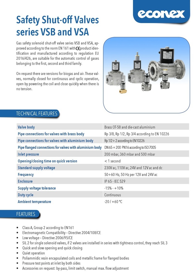
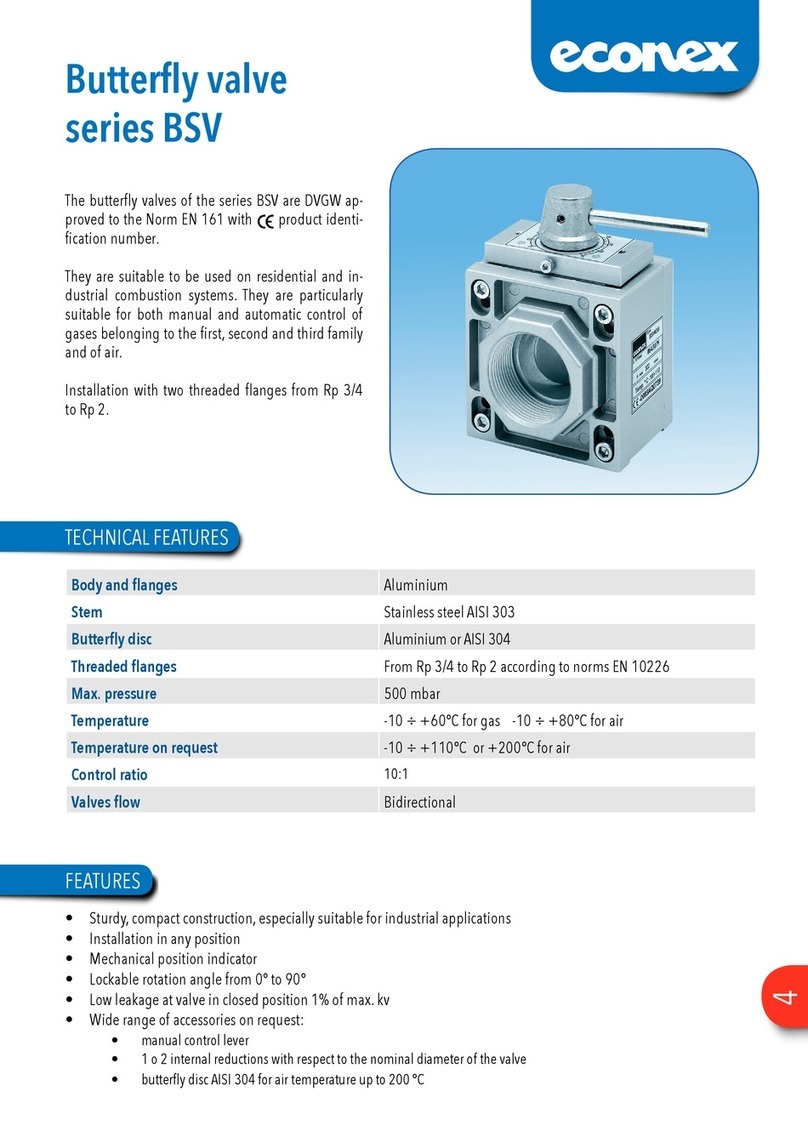
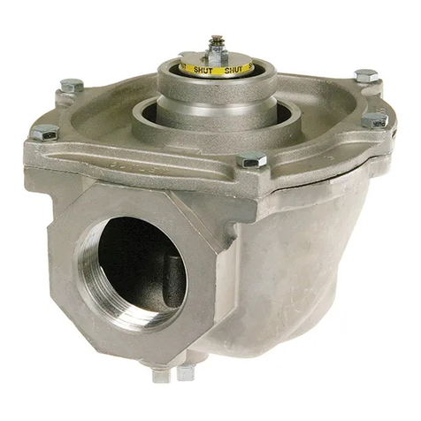
Econex MPV Series Instruction Manual

1 of 11
MODULATING CONTROL VALVE
SERIES MPV
INSTRUCTIONS FOR THE
INSTALLATION AND MAINTENANCE
1. MAIN FEATURES 2
2. TECHNICAL FEATURES 2
3. INSTALLATION 3
4. ELECTRIC CONNECTIONS 4
5. WIRING 5
5.1 WITHOUT MANUAL/AUTOMATIC CONTROL STATION 5
5.2 WITH MANUAL/AUTOMATIC CONTROL STATION 6
6. AUXILIARY MICROSWITCHES 7
7. POTENTIOMETER/S 7
8. CONTROL STATION 7
9. CALIBRATIONS 8
9.1 LIMIT SWITCH 8
9.2 POTENTIOMETER/S9
9.3 ELECTRONIC CARD 10
9.4 MAX.CAPACITY ADJUSTMENT 11
10. START-UP 11
11. MAINTENANCE AND CHECKS 11
12. REPLACEMENT 11

2 of 11
1. MAIN FEATURES
The modulating valves in the MPV [Modulating Plug Valve] series have been designed
with a modern concept and they are DVGW approved, with CE identification number.
They are suitable to be used in commercial and industrial combustion systems.
They are especially suitable for the proportional adjustment of non corrosive fuel gases
from the first, second and third family and air. The MPV valve is an adjustment device
without zero closing. The actuator is equipped with a single-pole bi-directional motor
with high static torque and holding torque for 3-positional control or electronic
modulation with analogic signal current [4 ÷ 20 mA] or tension [0 ÷ 10 Vdc] variation
at. The adjustment of flow volume in the valve operates by a delivery adjusting
cylinder with linear characteristics. The cylinder rotation changes the passage opening
and the flow volume is adjusted according to a linear trend.
Three different orifice sizes are available according to the operating conditions,
interchangeable without removing he valve from the plant.
W
ARNING
Installation, wirin
g
, ad
j
ustment and maintenance of
g
ear motors must be carried out
e
xclusively by skilled and authorized service technicians. Non-proper installation,
a
d
j
ustment, modifications, use and maintenance may cause in
j
uries to the staff or
material dama
g
es. It is therefore necessary to respect strictly the followin
g
instructions and local prescriptions for the installation of electric and gas devices.
2. TECHNICAL FEATURES
Operating pressure : max. 500 mbar
Valve group : 2
Ambient temperature : from -10 to +60°C
Adjusting ratio : 25:1
Fittings : Rp 1, according to ISO 7-1
Delivery feature : linear
Valve : without zero closing
Available voltage : 230 Vac / 50 - 60 Hz
115 Vac / 50 - 60 Hz
24 Vac / 50 - 60 Hz
Nominal load : 7 VA
Electric protection : IP 54 according to EN60529
Duty cycle : continuous 100%
Cable fasteners : 2 x Pg 13.5
Opening/closing times : 30 ÷ 60 seconds at 50 Hz
Limit - Aux. switches rating : 5 [1] A 250 Vac
Available potentiometers : 150, 1000 [standard], 2500 ohm
Control signal : 4 ÷ 20 mA [only with supply voltage 24 Vac]
[for electronic version] : 0 ÷ 10 Vdc [only with supply voltage 24 Vac]
Accessories : adjustable manual by-pass

3 of 11
3. INSTALLATION
3.1 Make sure that all the operating data shown on the valve label comply with the
system operating data.
3.2 When installing the valve be sure that there is sufficient clearance above the
gear cover and that it can be easily accessible in order to perform the electrical
connections and the calibration of the electric limit switches.
3.3 Install a filter before the MPV valve.
3.4 Before installing the valve, make sure the piping is clean and free of every
impurity, and it is perfectly aligned with the valve body and not subject to
vibrations.
3.5 Remove the protection plugs installed on the valve body.
3.6 The sealant must be applied only on the piping outer threading and not on the
valve inner threading. Use gas suitable sealants only.
3.7 Comply with the gas flow direction marked by the arrows on the valve body.
3.8 The MPV valve installation can be carried out in every position.
3.9 The MPV valve can be installed in every premise included in the range of the
electric protection IP 54, except for premises with presence of acid fumes or
other vapours that can etch the metal parts, in atmosphere with gas or
explosive vapour leaks.
3.10 For the installation of the MPV valve on the piping do not use the actuator as
lever, rather use the suitable wrench.
3.11 Install the MPV valve without voltage.

4 of 11
4. ELECTRIC CONNECTIONS
4.1 Arrange the wiring and the grounding according to the local norms in force.
4.2 To access the inner terminal board and for the electric connections, remove the
cover loosening the 4 fastening screws.
4.3 Two threaded holes for cable pressers Pg 13.5 are already arranged on the
base of the electric actuator.
4.4 Before servicing make sure, that power supply is disconnected by means of the
two-pole-switch [phase and neutral]; in case of non-observance, damages to
people and equipments may occur.
4.5 All wires must comply with local prescriptions and, in any case, their section
must be ranging between 1 and 1.5 mm2. Connection piping recommended
H07V-U…G1.5 mm2.
4.6 Wiring diagrams are reported in the attached technical bulletin and on the plate
inside the cover.
4.7 Auxiliary microswitches are single-pole double through and voltage-free.
4.8 If a potentiometer is installed, its resistance value is indicated on the
nameplate.
4.9 Make sure the supply voltage and the system frequency correspond to those
indicated on the valve plate.
4.10 Low-tension signalling cable [tension lower than 48V] must be laid separately
from the higher-tension conduits [tension higher than 48V]. In case they are
laid in a single channel, screened cables must be used.

5 of 11
5. WIRING
The wiring schemes refer to the valve in “closed” [0°] position.
5.1 WITHOUT MANUAL/AUTOMATIC CONTROL STATION
TERMINAL BOARD
Terminal earthing
Terminal N1 N = neutral
Terminal L2 by tension the valve closes
Terminal 3 by tension the valve opens
Terminal 4 for manual electric operation
Terminal 16 answer signal when the valve reaches the “open” position
Terminal 17 answer signal when the valve reaches the “closed” position

6 of 11
5.2 WITH MANUAL/AUTOMATIC CONTROL STATION
Terminal earthing
Terminal 1 N = neutral
Terminal 2 by tension the valve closes
Terminal 3 by tension the valve opens
Terminal 4 for manual electric control
Terminal 16 answer signal when the valve reaches the “open” position
Terminal 17 answer signal when the valve reaches the “closed” position
6.3 Auxiliary microswitches
Terminal 20 common contact from the auxiliary microswitch S3
Terminal 21 normally open contact of the auxiliary microswitch S3
Terminal 22 normally closed contact of the auxiliary microswitch S3
Terminal 23 common contact from the auxiliary microswitch S4
Terminal 24 normally open contact of the auxiliary microswitch S4
Terminal 25 normally closed contact of the auxiliary microswitch S4
6.4 Potentiometer/s for answer signal of the position Pot. A and/or Pot. B
Terminal 30 max. value
Terminal 31 cursor
Terminal 32 min. value
Terminal 33 max. value
Terminal 34 cursor
Terminal 35 min. value

7 of 11
6. AUXILIARY MICROSWITCHES
On request, the valve can be equipped with 2 auxiliary microswitches that can be
adjusted in any position.
Microswitches are voltage-free.
The contact capacity is 5 A/250 Vac with ohmic load and 1 A/250 Vac with inductive
load.
Contact rating is about 5 A/250 with Ohm load and about 1 A/250 with inductive load.
For adjusting the cams of auxiliary microswitches, proceed as for cams of endswitches
as indicated in paragraph 9.1 chapter 9 “CALIBRATIONS”.
7. POTENTIOMETER/S
On request, the valve can be equipped with 1 or 2 independent potentiometers [pot. A
and/or Pot. B] for the answer signal of the valve position.
Resistance value of the potentiometer is indicated on the identification label.
If the resistance value does not correspond to the wished one, proceed as indicated in
paragraph 9.2 of chapter 9 «CALIBRATIONS».
Absorbed power is 2 W for each potentiometer.
8. CONTROL STATION
8.1 The control station enables the manual electric activation of the valve.
8.2 Phase L must be connected to the terminal no. 4.
8.3 The AUTO/MAN switch is delivered by the factory in AUTO position .
8.4 Set the AUTO/MAN switch in the manual position indicated by stylized hand
8.5 Activate the Open/Stopped/Closed switch as follows:
8.5.1 Keeping the lever pushed towards the symbol ◄the valve opens [the cam S2
adjusts the desired final opening position].
8.5.2 Keeping the lever pushed towards the symbol ►the valve closes [the cam S1
adjusts the desired final closing position].
8.5.3 Positioning the lever to the centre, the valve motor is not activated.
8.5.4 ATTENTION: after the operations for manual electric activation of the valve,
reset the AUTO/MAN switch onto AUTO position .

8 of 11
9. CALIBRATIONS
9.1 LIMIT SWITCH
9.1.1 The MPV valve is delivered by the factory in closed position. The limit switches
are adjusted to reach the positions of closed valve and completely open valve.
9.1.2 For “OPEN” position adjustment, it is necessary to operate on cam “S2”.
9.1.3 For cam adjustment, use the proper “half-moon” key, supplied with the
actuator and installed inside it.
9.1.4 Use the key from the right side, introducing the pin into one of the holes on
the sides of the blue cam of the cam involved and lever it to required position.
9.1.5 If the blue cam is in a behind position, use at first the lever on its curved side
to move the blue cam to a more suitable position to perform adjustment
[picture 1].
Picture 1
9.1.6 To calibrate, refer to the mechanical position indicator disc; the valve is closed
when the mechanical pointer is in the 0 position, the valve is completely open
when the mechanical pointer is in the 90° position.
9.1.7 The cam adjustment is possible in both directions.
9.1.8 The lever roller operates the microswitch when it is on the bottom of the cam
groove, stopping the motor rotation.
9.1.9 Remove the wrench before starting the actuator.
9.1.10 The movable crown can be driven also by a small screwdriver, acting on the
suitable notches.
9.1.11 Avoid valve rotation over 90°, in order to prevent damage on the adjusting
cylinder, and/or force the potentiometer shaft rotation.

9 of 11
9.2 POTENTIOMETER/S
9.2.1 The potentiometer shaft is frictioned and is accessible from the upper side
inside the gear motor.
9.2.2 Disconnect the cables connected with the regulation system from the
respective terminals n. 30, 31 and 32 [Pot. A] and, if necessary, n. 33, 34 and
35 [Pot. B].
9.2.3 By means of a suitable screwdriver with 5 mm cut rotate the potentiometer
shaft and measure the resistance value of 0 Ohm between terminals n. 31 and
32 and, if necessary, also between terminals n. 34 and 35 when the valve is
closed [picture 2].
Picture 2
9.2.4 By rotating the potentiometer:
●clockwise 3the resistance value increases
●counter dock wise 4the resistance value decreases
9.2.5 The gearbox between the gear motor shaft and the potentiometer shaft is
foreseen for a 90° rotation angle between closed valve and totally open valve.
Hence should the gear motor opening be reduced with a rotation angle lower
than 90°, the variation of the potentiometer resistance value will be
proportionally reduced.
If, vice versa, the rotation angle had been wrongly adjusted over 90° there
will be no increase in the resistance value beyond the plate maximum value.

10 of 11
9.3 ELECTRONIC CARD
9.3.1 Supply the servocontrol as per schema SE.
9.3.2 Select the MAN function
9.3.3 Position the adjustment instrument on 4 mA [or on 0 Vdc].
9.3.4 Turn the servocontrol manually till reaching the mechanical zero.
9.3.5 Adjust the closing cam «S1» at few degrees before microswitch involvement.
9.3.6 Turn the potentiometer shaft clockwise 3till it stops mechanically.
9.3.7 Select the AUTO position
9.3.8 Set the adjustment device on 6 mA [or on 2 Vdc] and wait up the servocontrol
moves, then take it back to 4 mA [or on 0 Vdc] and check it reaches 0 degrees.
9.3.9 If it does not exactly come back to 0 degrees, turn the potentiometer shaft
counterclockwise 4till 0 degrees.
9.3.10 Set the adjustment device at 20 mA [or on 10 Vdc] and check the max.
opening, then calibrate the opening cam «S2» at few degrees before the
microswitch involvement.
9.3.11 Set the adjustment device on 4 mA [or on 0 Vdc] regulating the servocontrol
back to 0 degrees.

11 of 11
9.4 MAX.CAPACITY ADJUSTMENT
9.4.1 To reduce the max. capacity fit a 3 mm hexagon socket screw in the suitable
seat on the lower part of the valve body and rotate it counterclockwise 4.
9.4.2 The MPV valves are supplied by the factory adjusted for the max. capacity.
10. START-UP
10.1 Before starting the system up, carefully check the following points of the MPV
valve:
- correct installation according to the flow direction
- gas outer seals
- correct electric connections and grounding
- perfect electric and mechanical operation by opening and closing with closed
gas main cock.
Once preliminary conditions compliance, the gas main cock can be opened and
the operating test can be carried out.
11. MAINTENANCE AND CHECKS
11.1 The MPV valve does not require any special maintenance.
Both the valve body and the actuator do not need any lubrication.
11.2 At least once a year, and above all for systems subject to vibrations, it is
recommended to check the harness for faulty contacts of the terminal board
and to tighten the screws.
12. REPLACEMENT
For replacement of MPV valve, operate as follows:
12.1 Close the gas main cock.
12.2 Cut off the supply voltage to the valve.
12.3 Remove the actuator cover.
12.4 Disconnect all the electric connections, noting the cable numbers.
12.5 Remove the valve body from the piping.
12.6 Install the new valve according to the instructions of the previous chapters.
These instructions can be subject to possible variations without notice.
Table of contents
Other Econex Control Unit manuals
Popular Control Unit manuals by other brands
Agilent Technologies
Agilent Technologies Turbo-V user manual

Clack
Clack Water Specialist WS1TC Operation and instruction manual
Flotrol
Flotrol F20 SVE Installation and service manual
Elesa
Elesa UC-RF operating instructions

Bailey
Bailey infi 90 IMASI02 Instruction
Siemens
Siemens TMM-1 installation instructions
