Econoline 36-1 DP Instructions for use

36-1 DP
PLEASE READ
BEFORE
USING THIS EQUIPMENT


DP 36-1
Assembly Instructions
PLEASE READ INSTRUCTIONS COMPLETELY
BEFORE STARTING
We thank you for purchasing the DP-36 pressure system. This system has
been specifically designed for the Dry Blast user who wishes to achieve
quality results on a number of surfaces for both low and high volume
requirements. Below you will find instructions on how to assemble your
unit upon receipt. If you have any questions on how to proceed with any
steps, contact Econoline Technical Service by phone at 1-800-253-9968
or fax at 1-616-846-6341.
NOTICE:
The DP36 is delivered skid-mounted to assure safe arrival. If any damage
is evident upon receipt, contact the carrier immediately to file your claim.
STEP 1 – Unpacking
Cut the packing straps by using heavy-duty scissors or wire cutter.
Remove the protective plastic wrap and cardboard. Open the front
door by unlatching and remove the light assembly, regulator and foot
pedal. Using a crescent wrench, remove the bolts to loosen the unit
from the skid. With assistance of others, slide unit gently off the skid
and place unit in desired work area.
STEP 2 – Light Fixture Installation
Unwrap the fluorescent light fixture and attach to the top of the
cabinet with hardware provided. Be sure to place the plastic
protective sheet between the light fixture and the cabinet to protect the
light source from abrasive damage during blasting.
STEP 3 – Window
Loosen wing nuts to remove window frame and peel protective covering
off from the window. Re-install and firmly tighten wing nuts to prevent
leakage around window.

STEP 4 – Dust Collector set-up
Unpack the dust collector and place within a few feet of the sandblast
cabinet. (Note: vacuum hose is packed in bottom barrel of dust collector.)
Attach one end of the plastic hose to the air inlet of the vacuum system and
attach the other end to the air outlet on the rear of the blasting cabinet.
Plug the dust collector line cord into outlet on the back of the lamp box.
See your dust collector manual for details and operation of your dust
collector.
STEP 5 – Regulator and gauge installation
Connect regulator and gauge assembly (nos.1 & 9) to the inlet ball valve
(no. 3). Be sure to place Teflon tape on the thread to assure a leak-free fit.
Using a pipe wrench, tighten the connection. When the regulator and
gauge has been installed, place the pipe tee (no. 2) and filter to the left of
the regulator and gauge.
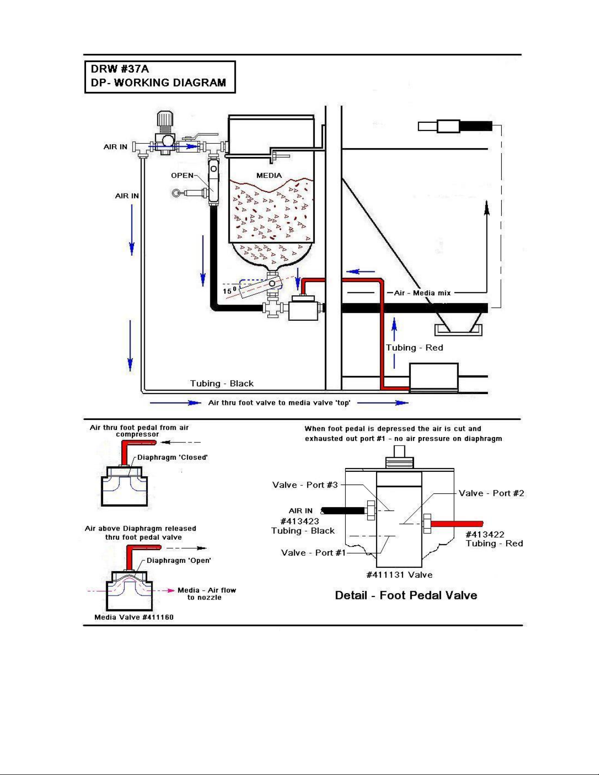
STEP 6 – Foot operated blast gun installation
Connect the black hose from the foot pedal valve to the brass hose barb in
the ¼ inch air filter (no. 12). Connect the red hose to the brass hose barb
on the media valve (no. 11).
*DO NOT USE QUICK DISCONNECTS*
STEP 7 – Attaching air line to sandblast system
NOTE: WE STRONGLY SUGGEST YOU HAVE A WATER / AIR
SEPARATOR PLACED BEFORE THE REGULATOR TO ASSURE
NO MOISTURE ENTERS THE SYSTEM. MOISTURE MAY LEAD
TO CLOGGING OF ABRASIVE MEDIA.
Close your air inlet ball valve (no. 3) and attach the airline from your
compressor to the pipe (1/2 inch NPT pipe thread) from your regulator and
gauge (or water / air separator if you have installed one). The “open”
position of the air inlet ball valve is when the lever is positioned over the
length of the valve. The “closed” position is when the lever is
perpendicular to the ball valve. When attaching the air supply to the DP-
36 the following assembly instructions are important for your system to
function properly.

*Air to the plumbing of your unit should be supplied by hose or pipe
with a minimum of 3/8” I.D. and we strongly suggest ½” I.D.
*Do not attach your air supply to the unit with quick connects, as
this greatly reduces the volume of air to the system and will
adversely affect the units performance.
*For your foot pedal and media valve to operate properly and to
maximize the life of the media valve and diaphragm – air line
pressure supplied to the regulator of the system must be maintained
at a constant 100 – 125 psi. (Note: this pressure is required to close
diaphragm in valve).
STEP 8 – Loading abrasive into pressure-pot
Pour the abrasive media into the pressure pot. Brush excess media into
the vessel to avoid it being sprayed into the air when filling the system
with air. The pressure pot holds up to 100 pounds of media for long
uninterrupted blasting. When reusing any abrasive media, be sure to
use a filter to remove any extraneous materials which could clog the
abrasive metering valve or the sandblast nozzle.
STEP 9 – Filling pressure-pot with air
Grip the pressure pot handle located in the top of the pressure vessel
and lift firmly to secure ball seal in the opening while simultaneously
opening the air inlet ball valve (no. 3) slowly. A swishing sound will
indicate that the vessel is being filled with air. After a few seconds,
the handle will stay in place on its own. If this is not the case, open
the ball valve further to allow the vessel to fully compress.
When the system is fully compressed, the ball valve should be in the
fully opened position. Check your regulator and gauge to assure the
PSI is still at the desired setting. If not, adjust the regulator by turning
the control located on top. Next, make sure that ball valve (no. 5) is in
the “open” position.

STEP 10 – Controlling the abrasive media flow
The pressure-pot is fitted with an abrasive metering valve (no. 5) located
on the bottom of the vessel. To adjust the valve, align the valve lever
perpendicular to the valve body (closed position). Now turn the lever
down approximately 30 degrees. This should be a good position to begin
adjusting the media flow. Slide your arms into the gloves in the arm ports
of the cabinet, grip the blast hose firmly, and depress the foot pedal to
begin blasting (it is normal when starting to blast that one or two spurts of
abrasives come out of the nozzle before uniform blasting begins). Best
blasting is achieved when the abrasive can barely be seen as a mist in the
air/media stream from the nozzle. Too much abrasive in the flow will
reduce the ability of the system to blast effectively and will cause surging.
Too little abrasive flow will slow your blasting and yield poor results.
Opening the abrasive metering valve will put more media into the mix
while closing it will deliver more air and less abrasive. Once the metering
valve is properly set, it will require only occasional maintenance.
STEP 11 – Blasting
Best results are achieved by sandblasting between 20 and 80 psi and
holding the nozzle at a 90 degree angle to the surface at about 4 to 8 inches
away. Maintain a continuous, even movement of the nozzle to prevent the
media from cutting too deep into your work surface.
NOTE: IF USING GLASS BEAD KEEP PRESSURE BELOW 40
PSI. GLASS BEAD SHATTERS INTO DUST ON CONTACT WITH
ITS TARGET AT PRESSURES OF 40 PSI AND ABOVE.
To stop blasting, release the foot pedal and the air media valve will shut
itself off automatically. To begin again, just press down on the foot pedal.
To shut down the system, simply close the air inlet ball valve (no. 3)
and press down on the foot pedal. The pressure relief valve (no. 12)
can be activated by pulling on the ring, however, depressing the foot
pedal is easier and can be accelerated by pulling on the pressure relief
valve simultaneously.

MAINTENANCE
To assure a long efficient life of the system, it is recommended to:
A. Replace nozzle when compressor can’t keep up, or media usage is
excessive.
B. Rebuild media valve when it starts to leak or doesn’t shut off.
C. Check abrasive metering valve when you can’t get correct abrasive
flow. If worn badly, replace.
D. Check hose barbs after 20 hours of use. If worn badly, replace.
E. Replace abrasive hose when it begins to soften or leaks media or air.
Water and/or oil in the air line will cause problems with the efficiency of
your blasting. Before blasting, always drain water and/or oil from air line.
We suggest that a quality water filter be installed in the air line between the
compressor and the blast cabinet.
Good visibility speeds up work. Clean dust from window often and
replace the plastic window underlayment and window when needed. The
lamp shield will also become frosted and require replacement. Visibility is
also affected by the condition of the dust collection system. The filter
should be cleaned often and the dust emptied from the canister regularly
(more than a gallon of debris is too much.)
If after extended use of the machine the gasket around the door or window
becomes damaged or worn, it can be replaced (see diagram).
This equipment is engineered to the finest point of simplicity. With
reasonable care it should give you many years of excellent service.
Blasting by its very nature is a high maintenance process. The
same forces acting to separate materials from targeted pieces
wear on the system itself.
Keep service parts in stock to avoid down time.

HELPFUL HINTS
1. Air compressor choice: Secure an air compressor that has
the capacity to produce a high volume (cfm) and high-pressure
(psi) of moisture –free air.
You must maintain a constant air pressure, not high one minute and
low the next, it must be constant.
2. Air supply line: Keep the air lines as short as possible.
DO NOT reduce the air line down to a quick disconnect when
attaching it to your blast equipment. In order to maintain the
high CFM and PSI you need at the blast nozzle; we suggest
using a minimum ½” I.D. air line from your compressor to the
blast machine.
3. Blast Nozzles: the blast nozzle size and design will
determine the cfm of air required. The larger the nozzle, the
greater the cfm needed.
4. As you begin blasting, record all data, compressor delivery
pressure, nozzle size (I.D.), regulator pressure, and abrasive
type and mesh size. When you are totally satisfied with your
results, be sure to record all data for future use and reference.

PARTS LIST FOR LARGE LIGHT BOX
COMPLETE ASSEMBLY #202835-LED
DESCRIPTION PART NUMBER
1. Light Box cover only 410466
2. Power Cord 411242
3. Light Switch (on/off) 411249
4. LED tube 7W / T8 / 5000K (2 required) 411240
5. Socket 411245
6. Lamp Shield – large (not shown) 411422
WARNING: This fixture has been modified and no longer operates fluorescent lamps. Ballast has
been removed and there is line voltage being supplied to sockets. DO NOT INSTALL FLUORESCENT
LAMPS.
411240 LED TUBE
#4
411245 Socket
#5
#3
411249
#
1
4104667
1
#7
411422
not shown
#2
411242

PARTS LIST FOR BLAST CABINET
DESCRIPTION Part #
411601
410545
18. Window frame
19. Window plexi-glass 12” x 24”
20. Window underlayment
1 piece 24” x 120”
10 pieces 12” x 24”
21. Window gasket material
(Specify number of feet required)
22. Latch assembly front door
23. Glove clamp (1 pair)
24. Gloves 24” x 6” seamless rubber (pair)
left hand only
right hand only
25. Armhole gasket
26. Front door gasket
27. Work table (expanded metal)
28. Side door handle assembly (set)
Consists of: Handle
Latch
29. Side door
30. Side door gasket
31. Lamp box gasket material
32. Lamp shield
33. Lamp box assembly complete
NOT SHOWN: Trap door spring
Trap door gasket
309344-66
411405
311535
313286
411403
411712
414511-2
412402
412402-L
412402R
411402
411403
201345
411701
411702
201326-66
411403
411403
411422
202835-LED


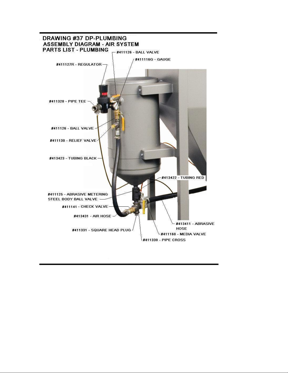
PARTS LIST FOR AIR SYSTEM – PLUMBING
DESCRIPTION PART NO.
1. Regulator 411127
2. Pipe Tee 411328
3. Inlet Ball Valve 411126
4. Air Hose ½” I.D. 413431
5. Choke Ball Valve 411126
6. Abrasive Metering Valve 411125
7. Pipe Cross 411330
8. Square Head Pipe Plug 411331
9. Gauge 411116G
10. Abrasive Hose (8’ required) 413411
11. Media Valve 411160
12. Pressure Relief Valve 411130
14. Check Valve 411141
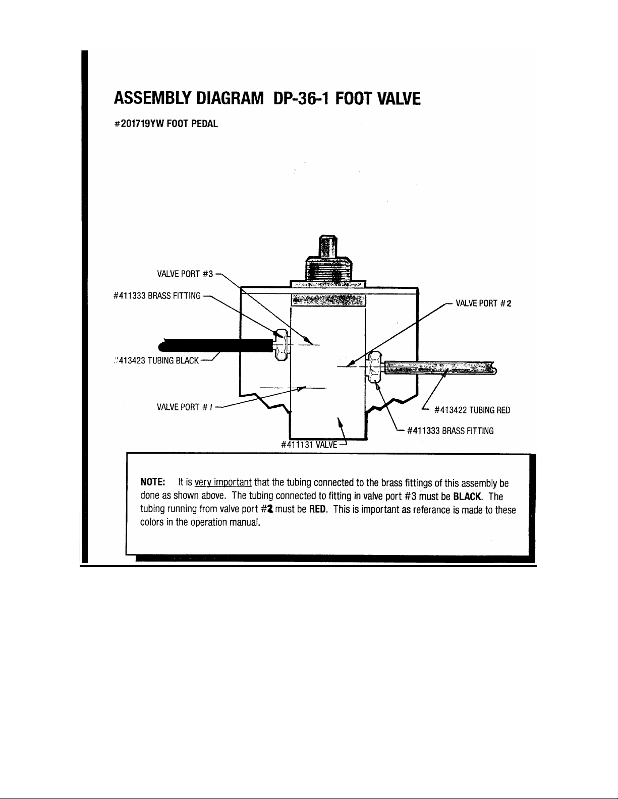
15. Foot Pedal Valve 411131
15A. Foot Pedal – Complete 201719YW
16. Tubing (black) 413423
17. Tubing (red) 413422
Not shown - Gasket Closure 3” dia. – red 411427


PLEASE READ
For optimum performance, we have included two
different media valve diaphragms.
Installed in the media valve is our high-pressure
diaphragm part #411157.
If the media valve does not shut off immediately upon
releasing the foot pedal, you may need to change the
diaphragm.
For lower pressure uses we recommend installing the
low-pressure diaphragm part #411164
Whenever the media does not shutoff, you should first
inspect the diaphragm for wear.


TROUBLESHOOTING TIPS
PROBLEM POSSIBLE SOLUTION
Surging of blast flow?
Air pressure too low------------------- See “Lack of Air”
Too much media----------------------- Adjust media valve
Excessive media consumption?
Media valve open too far------------- Close slightly
Air pressure too low------------------- Check pressure gauge
Clogging and plugging of blast flow?
Debris in media------------------------ Purge & screen
Media size too large------------------- Use smaller grit size
Nozzle plugs---------------------------- Use larger nozzle
Nozzle plugs---------------------------- Adjust media valve
Wet media------------------------------- Dry media, drain water from air
Moisture in abrasive media?
Wet media------------------------------ Change or use dry media
Water in air----------------------------- Drain water from air lines
Water in tank--------------------------- Empty, dry out and refill
Humid weather?
Moderate humidity-------------------- Keep media dry as possible
Moderate humidity-------------------- Use dryer or moisture separator
High humidity ------------------------- Avoid usage if possible
Overtaxed compressor?
Compressor too small ---------------- Restrict time used
Nozzle size too large ---------------- Use smaller size
Too many leaks in plumbing ------- Seal and tighten plumbing
Holes in abrasive hose---------------- Replace
Air filter on compressor-------------- Clean
Lack of air pressure?
Compressor too small ---------------- Use smaller nozzle
Supply valves not on full position--- Open valves
Nozzle size too large ---------------- Use smaller size
Leaks in plumbing--------------------- Seal & tighten plumbing
Holes in abrasive hose----------------- Replace hose
Air filter on compressor plugged----- Clean filter
Urethane gasket worn or dirty-------- Clean or replace gasket
Lack of abrasive flow?
Blaster tank empty--------------------- Fill tank
Moisture in media---------------------- Dry media
Not enough air pressure--------------- Check system
Abrasive hose kinked ----------------- Straighten
Debris in media------------------------- Clean or screen media

WARRANTY
ECONOLINE
THIS PRODUCT HAS BEEN MANUFACTURED AND ENGINEERED TO THE
HIGHEST STANDARDS.
FIVE YEAR WARRANTY
ECONOLINE ABRASIVE PRODUCTS GUARANTEES ITS BLAST CABINETS
AGAINST DEFECTS IN MATERIAL AND WORKMANSHIP FOR A PERIOD OF FIVE
YEARS FROM THE ESTABLISHED PURCHASE DATE. ECONOLINE WILL REPAIR
OR REPLACE, FREE OF CHARGE, ANY DEFECTIVE PARTS DETERMINED TO BE
COVERED UNDER THIS WARRANTY BY OUR FACTORY SERVICE PERSONNEL.
THE PARTS MUST BE RETURNED TO THE FACTORY, FREIGHT COLLECT, WITH A
LETTER OF EXPLANATION. ON ACCEPTANCE OF CLAIM ECONOLINE WILL
REPLACE DEFECTIVE PART.
CONDITIONS
THIS WARRANTY DOES NOT APPLY IF THE UNIT HAS BEEN MISUSED,
ALTERED, OR USED FOR ANY PURPOSE OTHER THAN IN ACCORDANCE WITH
THE OPERATING AND ASSEMBLY INSTRUCTIONS PROVIDED.
THIS WARRANTY DOES NOT COVER TRANSPORTATION, INTERIOR OR
EXTERIOR FINISHES, HOSE ASSEMBLIES, NOZZLES, AIR JETS, WINDOWS,
FILTERS, LAMPSHIELDS OR MEDIA VALVE.
OPERATION OF THIS UNIT WITH NATURAL
SAND SHALL RENDER THIS WARRANTY NULL
AND VOID.
WARNING
DO NOT USE SAND OR ANY ABRASIVE CONTAINING SILICA. USE
OF COMPOUNDS CONTAINING SILICA IS A HEALTH HAZARD.
FREE SILICA WHEN INHALED CAN LEAD TO SERIOUS,
PERMANENT, DISABLING AND DEADLY DISEASE (SILICOSIS).
Table of contents
Popular Industrial Equipment manuals by other brands


Mec
Mec TURBO-FLO LE ME806 Series Installation and operating instructions

VALLEY CRAFT
VALLEY CRAFT F88565C7 instruction manual

OP
OP TUBOMATIC H79 EL Use and maintenance manual

ABB
ABB HT569272 Operation manual

Gis
Gis GKU 1250 Translation of the original instruction manual

Festo
Festo KSK Series operating instructions