OWNERS MANUAL
LIMITED WARRANTY
All information contained in this owner manual is the property of P. A.
Ignition Co., Inc. and cannot be duplicated in whole or in part by any means
or disseminated or distributed without the prior written consent of P. A.
Ignitions Co., Inc. The information in this manual has been carefully
compiled and checked for accuracy and is believed to be correct. However,
P. A. Ignition Co., accepts no responsibility for inaccuracies which may
occur. All specifications in this manual are subject to change without
notice.
1) Use of any other spark plug wires other than resistor type wires with at
least 3,000 ohms of resistance. 2) Use of non-resistor spark plugs. 3)
Drilling or cutting of any kind into the module 4) Incorrect wiring of the
module. 5) Use of module on systems with defective charging systems. 6)
Use of defective coils. 7) Directly shorting the coil output wires to +12 VDC.
8) Physical damage to the ignition . 9) Any other items covered in the
warranty & instruction manual.
Power Arc Ignitions Co., Inc.
2518 N.E. 102 Ave.
Ankeny, IA 50021
(515) 964-7608
Any module returned under the warranty must include note of
explanation of failure and be accompanied by a dated bill of
sale.
The following customer actions automatically voids the warranty.
P. A. Ignition Co., Inc. warrants to the original retail purchaser of a
Power Arc IDS ignition that it will, free of charge, repair or replace at
its own option, the product if returned to P. A. Ignition Co., Inc. within
6 months after purchase and if found by P. A. Ignition Co., Inc. to be
defective in material or workmanship. This warranty is not
transferable by the purchaser and shall be voided: if alterations not
authorized by P. A. Ignition Co., Inc. are made in the equipment or if
the serial number or date of manufacture has been altered, defaced
or removed. Nor does this warranty apply: if the equipment has
been subjected to accident, misuse, improper hookup, damaged by
flood, fire, or act of God, or has been used on circuits or voltages
other than those indicated in its instruction manual. If the equipment
is found to be defective in materials or workmanship the equipment
will be returned and P.A. Ignition Co., Inc. will pay the return shipping
(this does not include next day shipping, second day shipping,
shipments outside of the continental U. S. A. or shipments outside of
the U.S.A.). All warranty work outside of the U.S.A. must include
prepayment of return shipping. Customs, duties or tariffs are not
covered by this warranty. If the equipment is found to be defective
but is due to customer misuse (as described in warranty) P. A.
Ignition Co., Inc. will notify the customer and if the customer wants
the defective equipment returned P. A. Ignition Co., Inc. will return
the equipment C.O.D. freight. If the equipment is found to be in
operational order when returned to the factory P. A. Ignition Co., Inc.
will return the module with a $30.00 service charge plus freight and
C.O.D. Charges.
P. A. Ignition Co., Inc. warranty obligations are limited to those set
forth herein and no other obligations, expressed or implied, are
assumed by P. A. Ignitions Co., Inc.
Some states do not allow the exclusions or limitations of incidental
or consequential damages, or allow limitations on how long an
implied warranty lasts, so the above limitations or exclusions may
no apply to you. This warranty gives you specific legal rights,
and you may also have other rights which vary from state to
state.
POWER ARC IDS-C1 HD
OWNER'S MANUAL
IDS-C1 HD Ignitions Systems
Multi-Spark 3 Sparks / Compression Stroke
Programmed Placement of Multi-Spark sparks
Automatic Coil Shutoff
Cam based sensor pickups
Dual Fire Operation
VOES Control Wire
Precision Rev limiter
Static Timing Light
Stainless Steel Encoder Disk
Corrected Tach Output
Ø
Ø
Ø
Ø
Ø
Ø
Ø
Ø
Ø
Ø
SPARK PLUG WIRES
SPARK PLUGS
Choice of spark plug wires is an important consideration when
using an electronic ignition system.
You must use a resistor spark plug with electronic ignitions.
Stock spark plugs are resistor type plugs and will work.
Spark plug gap should be limited to as small as possible, while
still maintaining performance.
A wide spark plug gap can cause the following problems: Hard
cold starting, misfires during rich or lean fuel conditions, and
reduction of upper rpm range.
Initial settings for spark plug gaps are:
Dual Fire -1 Plug per cylinder Multi-Spark 0.025"-0.032"
The higher the engine compression, the
more voltage required to fire the plug, and the narrower the plug
gap should be.
The higher the rpm's the less time the coil has to charge
to break over voltage or complete saturation. A narrower spark
plug gap will help high rpm stability.
To maintain a good secondary spark within a
wider rpm range it is wise to run a narrower spark plug gap. It is
better to precisely place two stable, consistent sparks than to fire
one wider spark that may cause misfires in rich or lean
conditions, or from any of the above reasons.
Many things effect spark plug gap settings:
Multi-Spark:
Compression Ratio:
RPM:
You must use carbon core
resistor or Spiral wound spark plug wires with at least 800
. Failure to observe these precautions
will damage Ignition & Void the Warranty.
Ω per foot resistance
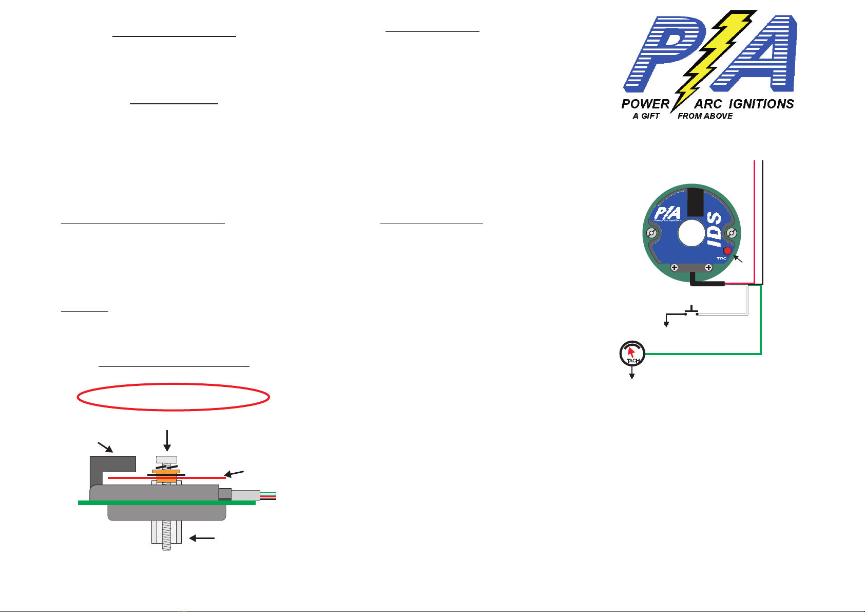
Encoder Installation and Cam end play
POWER ARC IGNITIONS CO., INC.
2518 N. E. 102 AVE.
ANKENY, IA 50021
(515) 964-7608
http://www.powerarc.com
PATENT #4,951,629 OTHER PATENTS PENDING
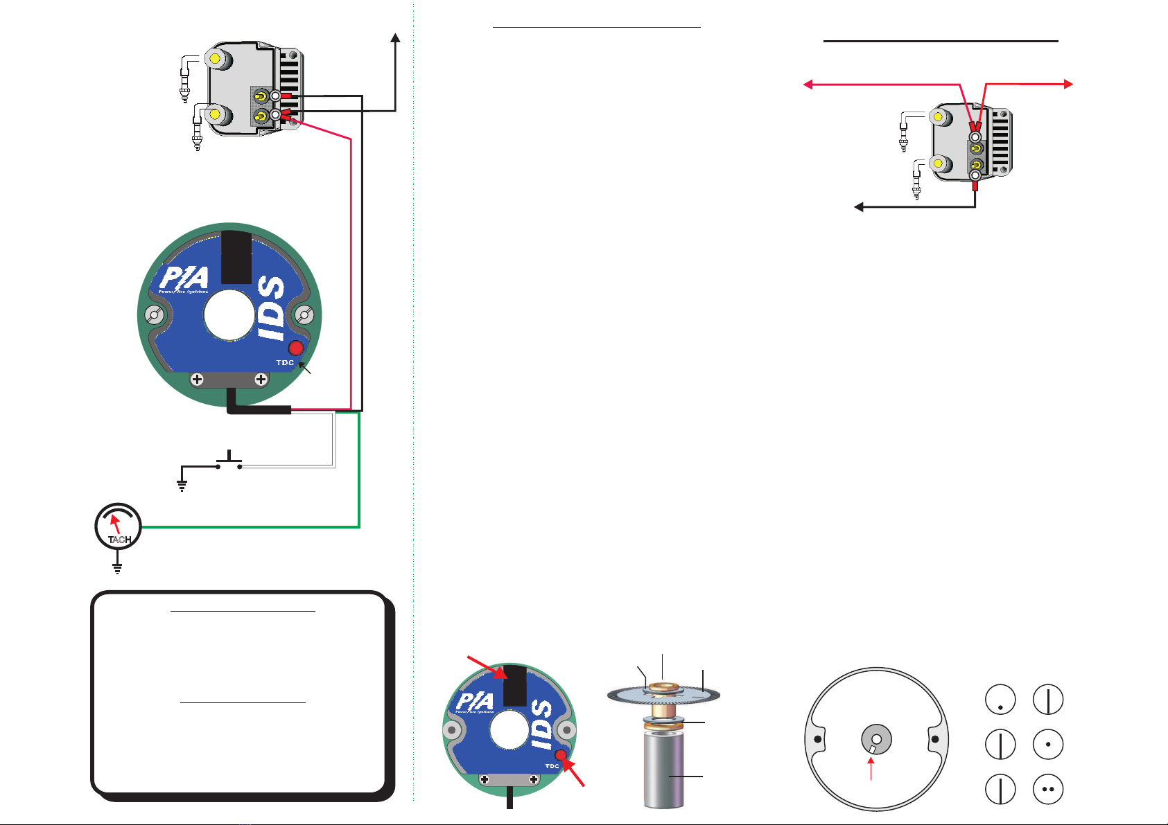
Green Tach
Trigger
TACH Factory Tach Wire
Normally Pink
VOES
SWITCH
White Sensor
(VOES)
Timing
Light
CONE MOUNT
(Negative Ground)
Red, Ignition Positive
Black, Coil Trigger
D
U
A
L
F
I
R
E
C1HD
Cam end play should not exceed 0.020”
Ignition
Encoder
Disk
Optical Pickup
Encoder
Adapter
Tighten applying to threads pink Loctite.
LocTite 222MS threadlocker for small fasteners to 1/4"
Extra washers may be included for shimming the
Encoder Disk outward. Place on encoder standoff
if Encoder Disk is to close to Optical Pickup.
Washers may be added
under Encoder Disk to
shim for correct height.