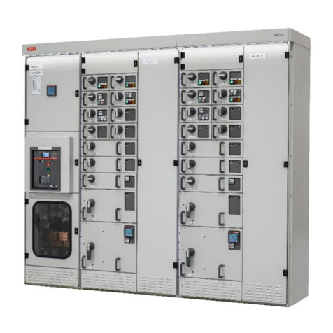
ABB SafeRing User manual

SafeRing / SafePlus 12-24kV
Installation and operating instructions
Product manual

2
CONTENTS
1. Safety 4
1.1 For your safety 4
1.2 Skilled personnel 4
1.3 Crucial information 4
2. General description 5
2.1 Outer assembly 6
3. Transport and handling 7
3.1 By receiving inspection 7
3.2 Storage 7
4. Technical data 8
4.1 Electrical data SafeRing 8
4.2 Electrical data SafePlus 8
5. Installation 9
5.1 Standard 3-way switchgear 9
5.2 3-way switchgear with base frame (AFL) 10
5.3 3-way switchgear with base frame (AFLR) 11
6. Dimensions 13
7. Internal arc classification (IAC) 14
8. Cable compartment 17
8.1 Standard cable compartment 17
8.2 Arc proof cable compartment 17
8.3 Cable connection 18
9. Extension of switchgear 19
9.1 External busbar 19
9.2 Side connection 19
10. Current and voltage transformers 19
11. Motor operation 20
12. Relay and current transformers 21
13. Pressure indicator 22
13.1 Gas pressure 22
13.2 Altitude 23
13.2.1 Adjustment of gas pressure 23
14. Operation of the switchgear 24
14.1 Operating conditions 24
14.2 General warnings and precautions 25
14.3 Putting into service 25
14.3.1 Preparatory work 25
14.4 Start-up 25

3
15 Operation 26
15.1 Operation of cable switch 26
15.2 Operation of vacuum circuit-breaker 27
15.3 Operation of vacuum circuit-breaker 12kV/25kA, 24kV/20kA 28
15.4 Operation of fuse-switch disconnector 29
15.5 Installation and replacement of fuses 29
15.6 Fuse selection tables 31
15.6.1 Fuse selection table - CEF 31
15.6.2 Fuse selection table - CEF-S 32
16. Metering module 33
17. Capacitive voltage indicators 34
17.1 Voltage indicators VPIS 34
17.2 Voltage indicators VDS 35
17.3 Voltage indicators VDS-LRM 35
18. Additional equipment 36
18.1 Low-voltage connections 36
18.2 Remote control and monitoring unit 36
19. Cable testing 37
19.1 Procedure for switchgear with test points 37
19.2 Procedure for testing directly on the cable 38
connector with the cable connected to
the switchgear
19.3 Procedure for testing directly on the cable 38
connector with the cable disconnected from
the switchgear
20. Service and maintenance 39
20.1 General warnings and cautions 39
20.2 Maintenance intervals 39
20.3 Inspection 39
20.4 Servicing 40
20.5 Repairs 40
20.6 Tool list SafeRing/SafePlus 41
21. Environmental certification 42
21.1 Life expectancy of product 42
21.2 Recycling capability 42
21.3 End-of-life 42

4
1. SAFETY
1.1 For your safety!
– Strictly follow these Installation and operating instructions.
– Only install switchgear in indoor conditions according to
IEC 62271-1 cl.2.1.
– Ensure that installation, operation and maintenance is
only carried out by professional personnel.
– Comply fully with the standards in force (IEC or local), the
connection conditions of the local power utility and the
applicable safety at work regulations.
– Observe the relevant information in the manual for all
actions involving the switchgear.
– Use gloves when installing or operating switchgear.
1.2 SKILLED PERSONNEL
All the installation, putting into service, running and main-
tenance operations must be carried out by skilled personnel
with in-depth knowledge of the apparatus.
When carrying out any maintenance work, the regulations in
the country of installation must be strictly obeyed.
Maintenance work must only be performed in a professional
way by trained personnel familiar with the characteristics of
the switchgear, in accordance with all the relevant IEC safety
regulations and those of other technical authorities, and also
respecting other overriding instructions. It is recommended
that ABB service personnel be called in to perform the servic-
ing and repair work.
1.3 CRUCIAL INFORMATION
Pay special attention to the information shown in the manual
by the following attention symbol:
After this symbol there are four different explanations indicat-
ing what types of injuries or damage can be caused should
the recommended precautions not be followed:
–DANGER - identifies the most serious and immediate
hazards which can cause serious personal injury or death
–WARNING - identifies hazards or unsafe practices which
can result in serious personal injury or death
–CAUTION - identifies hazards or unsafe practices which
can result in minor personal injury or product or property
damage
–NOTE - identifies important procedures or requirements
that, if not followed, can result in product or property
damage
WARNING
Make sure that the specified electrical ratings are
not exceeded under switchgear operating condi-
tions. Keep the manuals accessible to all personnel
involved in installation, operation and maintenance.
The user’s personnel are responsible for all matters
regarding safety in the workplace and correct use
of the switchgear.
WARNING
Always follow the instructions in the manual and
respect the rules of good engineering practice
(GEP)! Hazardous voltages can cause serious in-
jury or death! Disconnect the power and earth live
parts before proceeding with any work on the
switchgear. Follow the safety regulations in force in
the place of installation.
CONTACT US
If you have any further questions about this manual, our field
service team will be pleased to help. See the back cover of
this manual for contact information.

5
SafeRing 3-way unit CCV
2. GENERAL DESCRIPTION
SafeRing is a SF6-insulated ring main unit and SafePlus is a
SF6-insulated compact switchgear for applications in medium
voltage distribution networks. SafeRing and SafePlus offer a
sealed stainless steel tank which contains all the live compo-
nents and switching functions. The transformer is protected
either by a switch fuse combination or a vacuum circuit-
breaker.
The units are delivered from the factory ready for installation.
SafeRing can be supplied as a 2, 3 or 4-way unit in standard
configurations with additional equipment according to custo-
mer specification.
Available configurations:
DeF, CCF, CCC, CCCF, CCFF, DeV, CCV, CCCC, CCCV,
CCVV.
SafePlus has a unique flexibility due to its extendibility and the
possible combination of fully modular and semi-modular confi-
gurations, with a maximum of 5 modules in one SF6-tank.
The units are delivered from the factory ready for installation.
Routine tests are carried out on all units/ modules before
dispatch.
No special tools are required for installing the equipment.
Available modules are :
C - Cable switch
F - Switch fuse disconnector
D - Direct cable connection
De -Direct cable connection with earthing
V - Vacuum circuit-breaker
Sl - Busbar sectionalizer, load break switch
Busrise needed when SL on right side of SF6 tank
Sv -Busbar sectionalizer, vacuum circuit-breaker
Sv always together with busrise (total width=650 mm)
Be - Busbar earthing
M - Metering cubicle
V20, V25 - Vacuum circuit-breaker 20/25kA
Sv20, Sv25 - Busbar sectionalizer, vacuum circuit-breaker
20/25kA.
SafeRing / SafePlus with switch fuse combination in
compliance with IEC 62271-105.
With this unit the transformer will be protected by current-
limiting HV fuses in combination with a load break switch.
The load break switch is equipped with a stored spring energy
mechanism which can be tripped by the fuse striker pin.
SafeRing / SafePlus with vacuum circuit-breaker in
compliance with IEC62271-100
With this unit the transformer will be protected by a vacuum
circuit-breaker combined with relays and current transformers.
The standard relays are based on digital technology and do
not require an external power supply.
Further information can be found in the product catalogue for
SafeRing and SafePlus, 1VDD006104 GB.

6
2.1 OUTER ASSEMBLY
Upper front cover
1. Manometer
2. Nameplate of module
3. Short circuit indicator
4. Capacitive voltage indication
5. Load break / earthing switch position indicator
6. Push buttons close/open operation
7. Charged spring indicator
8. Self-powered protection relay
9. Vacuum circuit-breaker position
Lower front cover
10. Nameplate of switchgear
11. Fuse blown indicator
12. Disconnector / earthing switch position indicator
13. Capacitive voltage indication
Cable compartment cover
14. Cable compartment cover standard
15. Cable compartment cover with inspection window
16. Support bar (removable)
Side cover
17. Lifting lug
18. Operating handle (suspended on the side wall, by
default on the right-hand side wall)
� ��
SafePlus
17
1
2
3
4
10
11
56 7 8
9
18
12
13
14
16
15

7
3. TRANSPORT AND HANDLING
The units are delivered from the factory ready for installation.
3.1 BY RECEIVING INSPECTION
Upon receiving the SafeRing / SafePlus please check that the
delivered equipment has not been damaged during transport.
If any such damage has occurred, a claim must be submitted
to the carrier immediately.
After unpacking, the following must be checked:
1. Operating handle – one piece should be included, normally
fixed on right-hand side.
2. Check that the pointer on the pressure indicator is in the
green area.
3. Carry out a function test on the mechanical parts.
4. Visual check of the switchgear.
Any faults or omissions must be reported immediately to
the supplier.
3.2 STORAGE
SafeRing / SafePlus must be stored under cover in a dry and
well ventilated area until it is installed and put into operation.
NOTE:
Use only approved slings when lifting.
Maximum angle on lifting lugs is set to 60o.
Weight table
Maximum weights for standard SafeRing
2-way DeV 300 kg 2-way DeF 300 kg
3-way CCV 450 kg 3-way CCF 450 kg
4-way CCCV 600 kg 4-way CCCF 600 kg
4-way CCVV 600 kg 4-way CCFF 600 kg
3-way CCC 450 kg
4-way CCCC 600 kg
SafePlus
Standard 1-way 150 kg
2-, 3- and 4-way as for SafeRing
5-way 750 kg
M - metering module incl. trafo 250 kg
Mt - metering tariff module incl. trafo 350 kg
The weights are without additional equipment, except for
transformers for M- and Mt-modules
SafeRing / SafePlus is fitted with lifting lugs, but can also be
moved on a pallet with a forklift truck. Make sure to secure
the switchgear.
Max angle 60o

8
4. TECHNICAL DATA
4.1 ELECTRICAL DATA SAFERING
4.2 ELECTRICAL DATA SAFEPLUS
SafeRing
C-module F-module V-module
Switch
disconnector Earthing switch Switch-fuse
combination Earthing switch Vacuum
circuit-breaker Earthing switch
Rated voltage kV 12/17,5/24 12/17,5/24 12/17,5/24 12/17,5/24 12/17,5/24 12/17,5/24
Power frequency withstand voltage kV 286)/38/50 286)/38/50 286)/38/50 286)/38/50 286)/38/50 286)/38/50
Impulse withstand voltage kV 95/95/125 95/95/125 95/95/125 95/95/125 95/95/125 95/95/125
Rated current A 630/630/630 2001) 200/200/200
Breaking capacities:
active load A 630/630/630
closed loop A 670/670/670
off load cable charging A 141/141/141
off load transformer A 20/20/20
earth fault A 205/160/160
earth fault cable charging A 117/91/91
short-circuit breaking current kA see 2) 16/16/16
Making capacity kA 52,5/40/40 52,5/40/40 see 2) 12,5/12,5/12,5 40/40/40 40/40/40
Short time current 0,5 sec 3) kA 16/16/16
Short time current 1 sec 4) kA 5/5/5 16/16/16
Short time current 3 sec 5) kA 21/16/16 21/16/16 16/16/16
1) Depending on the current rating of the fuse-link 2) Limited by high voltage fuse-links 3) Maximum rating for bushings Interface A (200 series plug-in)
4) Maximum rating for bushings Interface B (400 series plug-in) 5) Maximum rating for bushings Interface C (400 series bolted)
6) GOST version is available with 42kV power frequency withstand voltage
SafePlus
C-module F-module V-module V20/V25 module
Switch
disconnector
Earthing
switch
Switch-fuse
combination Earthing switch
Vacuum
circuit-
breaker
Earthing
switch
Vacuum
circuit-
breaker
Earthing
switch
Rated voltage kV 12/17,5/24 12/17,5/24 12/17,5/24 12/17,5/24 12/17,5/24 12/17,5/24 12/24 12/24
Power frequency withstand voltage kV 281)/38/50 281)/38/50 281)/38/50 281)/38/50 281)/38/50 281)/38/50 281)/50 281)/50
Impulse withstand voltage kV 95/95/125 95/95/125 95/95/125 95/95/125 95/95/125 95/95/125 95/125 95/125
Rated current A630/630/630 200 2) 630/630/630 630/630
Breaking capacities:
closed loop A650/650/650
off load cable charging A140/140/140
off load transformer A20/20/20
earth fault A205/160/160
earth fault cable charging A117/91/91
short-circuit breaking current kA see 3) 21/16/16 25/20 25/20
Making capacity kA 65/52,54)/52,5 62,5/52,54)/50 see 3) 12,5/12,5/12,5 52,5/40/40 52,5/40/40 65/50 62,5/50
Short time current 0,5 sec 5) kA 16/16/16
Short time current 1 sec 6) kA 25/-/- 25/-/- 5/5/5 16/16/16 25/21 25/21
Short time current 3 sec 7) kA 25/214)/21 25/214)/21 21/16/16 21/16/16 25/21 25/21
1) GOST version is available with 42kV power frequency withstand voltage 2) Depending on the current rating of the fuse-link 3) Limited by high voltage fuse-links
4) Tested at 15,2 kV 5) Max. rating for bushings Interface A (200 series plug-in) 6) Max. rating for bushings Interface B (400 series plug-in)
7) Max. rating for bushings Interface C (400 series bolted)
9
5. INSTALLATION
NOTE
The floor must be well leveled and the unit must be
fixed by means of anchor bolts in accordance with
the dimensional drawing for the number of modules
or units as appropriate.
The tolerance of the evenness is maximum 1 mm per meter.
Unit A B C
1-way 298 337 371
2-way 623 662 696
3-way 948 987 1021
4-way 1273 1312 1346
5-way 1598 1637 1671
5.1 STANDARD 3-WAY SWITCHGEAR
NOTE
The tools required for installation and maintenance
of the switchgear are specified in the tool list in
chapter 20.6.

10
5.2 3-WAY SWITCHGEAR WITH BASE FRAME (AFL)
Unit A B C
1-way NA NA NA
2-way 623 662 696
3-way 948 987 1021
4-way 1272 1312 1346
5-way 1597 1637 1671

11
Unit A B C
1-way NA NA NA
2-way 623 662 696
3-way 948 987 1021
4-way 1273 1312 1346
5-way 1598 1637 1671
5.3 3-WAY SWITCHGEAR WITH BASE FRAME (AFLR)
Distance between two units which are connec-
ted to each other by means of external busbars
*) Top extension: 8 mm / 81 mm
Side extension: 14 mm / 87 mm
indicates cable entry
81/87*
8/14*

12
AFLR baseframe
* Dimensions for 290 mm baseframe
Base frame, height 450 mm Base frame, height 290 mm
Standard switchgear installed on cable
trench
Low version switchgear installed on cable
trench
39
38
1786
1045
3938
1626
885

13
6. DIMENSIONS
Height (mm) Standard switchgear Lower version switchgear
Non IAC/IAC AFL
without base frame
Non IAC/IAC AFL with
290 mm base frame
Non IAC/IAC AFL with
450 mm base frame
IAC AFLR with
290 mm base frame
IAC AFLR with
450 mm base frame
Non IAC/IAC AFL
without base frame
Non IAC/IAC AFL with
290 mm base frame
Non IAC/IAC AFL with
450 mm base frame
without low
voltage
compartment or
top entry box
Standard 1336 1626 1786 2002 2002 1100 1390 1550
Top connection without dead ends 1466 1756 1916 2002 2002 1230 1520 1680
Top connection with dead ends 1561 1851 2011 2002 2002 1325 1615 1775
External busbars 1591 1881 2041 2002 2041 1355 1645 1805
Busbar cover 1651 1941 2101 2002 2101 1415 1705 1865
with
top entry box
(124 mm)
Standard 1460 1750 1910 2002 2002 1224 1514 1674
Top connection without dead ends 1466 1756 1916 2002 2002 1230 1520 1680
Top connection with dead ends 1561 1851 2011 2002 2011 1325 1615 1775
External busbars 1591 1881 2041 2002 2041 1355 1645 1805
Busbar cover 1651 1941 2101 2002 2101 1415 1705 1865
with low voltage
compartment
(470 mm) *)
Standard 1806 2096 2256 2096 2256 1570 1860 2020
Top connection without dead ends 1806 2096 2256 2096 2256 1570 1860 2020
Top connection with dead ends 1806 2096 2256 2096 2256 1570 1860 2020
External busbars 1806 2096 2256 2096 2256 1570 1860 2020
Busbar cover 1806 2096 2256 2096 2256 1570 1860 2020
with low voltage
compartment
(700 mm) *)
Standard 2036 2326 2486 2326 2489 1800 2090 2250
Top connection without dead ends 2036 2326 2486 2326 2486 1800 2090 2250
Top connection with dead ends 2036 2326 2486 2326 2486 1800 2090 2250
External busbars 2036 2326 2486 2326 2486 1800 2090 2250
Busbar cover 2036 2326 2486 2326 2486 1800 2090 2250
*) For V-module 12kV/25kA and 24kV/20kA height of low voltage compart-
ment is 570 / 800 mm, so 100 mm has to be added to the total switch-
gear heights in the table

14
7. INTERNAL ARC CLASSIFICATION (IAC)
During development of all ABB products, focus is put on
personnel safety. This is why the SafeRing/SafePlus portfolio
was designed and tested for a variety of internal arc scenarios
in order to withstand an internal arc of the same current level
as a maximum short circuit current. The tests show that the
metal enclosure of Safering/SafePlus switchgear is able to
protect personnel standing close to the switchgear during an
internal arc fault.
Causes and effects of IAC
An internal arc is a highly unlikely fault, although it can theore-
tically be caused by various factors, such as:
−Insulation defects due to quality deterioration of the
components. The reasons can be adverse environmental
conditions and a highly polluted atmosphere.
−Inadequate training of the personnel in charge of the instal-
lation, leading to incorrect installation of the cables.
−Breakage or tampering of the safety interlocks.
−Overheating of the contact area, e.g. when the connections
are not sufficiently tightened.
−Short circuits caused by small animals that have entered
into the cable compartment (i.e. through cable entrance).
The energy produced by the internal arc causes the following
phenomena:
−Increase of the internal pressure.
−Increase of the temperature.
−Visual and acoustic effects.
−Mechanical stresses on the switchgear structure.
−Melting, decomposing and evaporation of materials.
Tested according to IEC standard 62271-200
The capability of SafeRing/SafePlus switchgear to withstand
an internal arc is proven by the type test according to Inter-
nal arc classification (IAC) as described in the standard IEC
62271-200 as follows:
Accessibility: A, B or C (switchgear)
A=Accessible to authorized personnel only
B=public access
C=not accessible due to installation
F-Front=Access from the front
L-Lateral=Access from sides
R-Rear=Access from the rear
All test specimens passed the following test criteria according
to the standards:
−Correctly secured doors and covers do not open
−No fragmentation of the enclosure occurs within the time
specified for the test. Projection of small parts, up to an
individual mass of 60 g are accepted
−Arcing does not cause holes in the enclosure of the switch-
gear up to a height of 2 m
−Indicators do not ignite due to the effect of hot gases
−The enclosure remains connected to its earthing point
Arc duration and damage caused
Melting of
Steel
Melting of
Copper
Melting of
Cables
0 100 200 500 ms
kA2s
R
L
L
F

15
WARNING
Distance from side wall: 20 mm. If installed more
than 20 mm from sidewall, an arc shield is re-
quired. For easier installation, it is recommended
that any switchgear requiring arc shields is in-
stalled minimum 300 mm from sidewall.
When installing Ring Main Unit or Compact Switchgear
with Internal Arc Classification AFL with ventilation be-
hind the switchgear, the following must be considered:
−Unit must be equipped with arc proof cable covers.
−Distance from floor to roof must be minimum 2400 mm
−Distance from back of unit to wall must be 100 mm
−Arc shields with height 650 mm must be mounted
−If unit is freestanding (i.e. distance from back of unit to wall
exceeds 100 mm), the area behind the unit must be restric-
ted and not accessible.
* Arc shield.
Height of arc shield for M-module is
1317 mm
* 1100 mm version available as optional
solution
For installation of switchgear with Internal Arc Classi-
fication AFL with ventilation down in cable trench, the
following must be considered:
−Unit must be equipped with arc proof cable covers
−Distance from floor to roof must be minimum 2000 mm
−Distance from back of unit to wall must be 100 mm
−Cable compartment back plate has to be mounted
−Length of cable trench must be 2000 mm, with an opening
of minimum 0,5 m2
−Minimum dimensions of cable trench are 230 x 355 mm
*
Marked area is restricted, but installation is allowed if mount-
ing of arc shield is feasible.
20 - 300 mm

16
*) 290 mm base frame is available as
option
For installation of switchgear with Internal Arc Classifi-
cation AFLR with ventilation upwards through exhaust
channel, the following must be considered:
−Unit must be equipped with arc proof cable covers
−Unit can be installed as free standing
−Minimum height of ceiling: 2600 mm
−Recommended distance from back wall is 100 mm

17
8.1 STANDARD CABLE COMPARTMENT
Removal of cable cover:
1. Loosen the screws on the cable cover, pull out and lift
cover off.
2. Removal of front section.
3. Front section removed.
4. The mid-panel can be removed by unscrewing Ax2 and B.
8.2 ARC PROOF CABLE COMPARTMENT
Removal of cable cover:
1. Lift handle to remove the cable cover, pull out and lift
cover up.
2. Removal of front section.
3. Front section removed.
4. The mid-panel can be removed by unscrewing Ax2 and B.
8. CABLE COMPARTMENT
CAUTION
In case of interlocked cable compartment, cover
can be opened / closed only when earthing switch
is in closed position.
NOTE
The tools required for installation and maintenance
of the switchgear are specified in the tool list in
chapter 20.6.
A
B B
A

18
8.3 CABLE CONNECTION
SafeRing/SafePlus is equipped with external bushings which
comply with DIN47636T1 & T2/EDF HN 525-61 for termina-
tion of cables.
All bushings are situated in the same height from the floor and
are protected by the cable cover.
SafeRing / SafePlus can be supplied with the following bus-
hings for the various type of cubicles:
Type of module
Bushings C F V D, De,
V20/25
Interface A X X
Interface C XXXX
Cable adapters
Adapters from following manufacturers are recommended:
ABB Kabeldon
Südkabel
Tyco Electronics Raychem
Power Systems
3M
Euromold
NKT cables
Please see supplier documentation for details.
DANGER
The manufacturer’s installation instructions must
be followed. Be sure to lubricate the bushings
thoroughly with the silicone supplied.
Use only isolated cable connections.
Where cables are not connected, the earthing
switch must be locked in closed position or the
bushings must be fitted with dead end receptacles
before the unit is put into operation.
Adjustable cable support bar (additional equipment).
Earthing bar Cable clamp (additional equipment)
Interface C with
M16 x 2 metric threads
400 series, In = 630A
Interface A with plug
200 series, In = 200A

19
9. EXTENSION OF SWITCHGEAR
9.1 EXTERNAL BUSBAR
SafeRing and SafePlus can be equipped with an external
busbar. See separate instruction manual:
1VDD006006 GB.
9.2 SIDE EXTENSION
SafeRing and SafePlus can be equipped with a side extensi-
on. See separate instruction manual 1VDD006106GB.
10. CURRENT AND VOLTAGE TRANSFORMERS
SafeRing and SafePlus can be equipped with current and/or
voltage transformers.
Installation and maintenance manual: 1VLM000610
SafePlus
� ��
� �� � ��
SafePlus
� ��
SafePlus
� ��
SafePlusSafePlus

20
11. MOTOR OPERATION
Switches, vacuum circuit-breakers and earthing switches are
operated by mechanisms located behind the front panel. The
mechanisms for all the switches and breakers are operated
manually with the operating lever (standard), or are fitted with
motor operation (additional equipment).
The earthing switch and the disconnectors can only be ope-
rated manually. The earthing switches have mechanisms to
achieve fault making capabilities.
3PKE mechanism for load break switch (C-module)
1VDD200001
3PAE mechanism for fuse-switch (F-module) 1VDD200003 2PA mechanism for circuit-breaker (V-module) 1VDD200004
3PKSE mechanism for load break switch (C-module)
1VDD200002
Motor operation can be retrofitted. Use the manuals.
All units are delivered with drawings showing the electrical
circuits.
Installation instructions cover the following modules:
We reserve all rights in this document and in the information contained therein: Reproduction, use or disclosure to third parties
without express authority is strictly forbidden. © ABB Technology Ltd.
Edition
1.0
Document status
RELEASED
Responsible
NODIS
Title
SafeRing/SafePlus 12/24
Motor operation
complete on 3PKE
mechanism for C-, Sl- &
F6-modules
Language
EN/NO
Location
Date
Name
Prepared PPMV
Skien
2015-06-23 Espen
Fossen
Checked PPMV
Skien
2015-08-10 Asgeir
Elvestad
Approved
PPMV
Skien
2015-08-13
Magne
Reinholdt
ABB Technology Ltd. Document No.
1VDD200001
Sheet No.
1/34
SafeRing / SafePlus 12 / 24
Motor operation complete on 3PKE mechanism for
C-, Sl- & F6-modules
Installation Instruction
www.abb.com
We reserve all rights in this document and in the information contained therein: Reproduction, use or disclosure to third parties
without express authority is strictly forbidden. © ABB Technology Ltd.
Edition
1.0
Document status
RELEASED
Responsible
NODIS
Title
SafeRing/SafePlus 12/24
Motor operation
complete on 3PKSE
mechanism for C-& Sl-
modules
Language
EN/NO
Location
Date
Name
Prepared PPMV
Skien
2015-06-23 Espen
Fossen
Checked PPMV
Skien
2015-08-10 Asgeir
Elvestad
Approved
PPMV
Skien
2015-08-13
Magne
Reinholdt
ABB Technology Ltd. Document No.
1VDD200002
Sheet No.
1/41
SafeRing / SafePlus 12 / 24
Motor operation complete on 3PKSE mechanism
for C- & Sl-modules
Installation Instruction
www.abb.com
We reserve all rights in this document and in the information contained therein: Reproduction, use or disclosure to third parties
without express authority is strictly forbidden. © ABB Technology Ltd.
Edition
1.0
Document status
RELEASED
Responsible
NODIS
Title
SafeRing/SafePlus 12/24
Motor operation
complete on 3PAE
mechanism for F- &
SGT-modules
Language
EN/NO
Location Date Name
Prepared
PPMV
Skien
2015-06-23
Espen
Fossen
Checked PPMV
Skien
2015-08-10 Asgeir
Elvestad
Approved PPMV
Skien
2015-08-13 Magne
Reinholdt
ABB Technology Ltd. Document No.
1VDD200003
Sheet No.
1/45
SafeRing / SafePlus 12 / 24
Motor operation complete on 3PAE mechanism for
F- & SGT-modules
Installation Instruction
www.abb.com
We reserve all rights in this document and in the information contained therein: Reproduction, use or disclosure to third parties
without express authority is strictly forbidden. © ABB Technology Ltd.
Edition
1.0
Document status
RELEASED
Responsible
NODIS
Title
SafeRing/SafePlus 12/24
Motor operation
complete on 2PA
mechanism for V-& Sv-
modules
Language
EN/NO
Location Date Name
Prepared
PPMV
Skien
2015-06-23
Espen
Fossen
Checked PPMV
Skien
2015-08-10 Asgeir
Elvestad
Approved PPMV
Skien
2015-08-13 Magne
Reinholdt
ABB Technology Ltd. Document No.
1VDD200004
Sheet No.
1/45
SafeRing / SafePlus 12 / 24
Motor operation complete on 2PA mechanism for
V- & Sv-modules
Installation Instruction
www.abb.com
Other manuals for SafeRing
4
This manual suits for next models
1
Table of contents
Other ABB Industrial Equipment manuals
Popular Industrial Equipment manuals by other brands

RUD
RUD LRBK-FIX instructions

PCB Piezotronics
PCB Piezotronics ICP M320C20 Installation and operating manual

Jofemar
Jofemar J-2000 Guide manual

ROVEMA
ROVEMA VPK Series Operation manual

Samoa
Samoa LARIUS PNEUMATIC HOIST 30 operating instructions

PAW
PAW SolarBloC midi Premium Assembly, installation and operation instructions

Pfeiffer Vacuum
Pfeiffer Vacuum OME 25 HP operating instructions

OSO HOTWATER
OSO HOTWATER Nano - N 5 manual

HEIDENHAIN
HEIDENHAIN ECN 413 Mounting instructions

Siemens
Siemens 3RK1405-1SE15-0AA2 Original operating instructions

Siemens
Siemens SINUMERIK 808D ADVANCED T user manual

BIG
BIG HSK-A63 Operation manual