Master Language is English Hot Runner System Installation Guide SVC-17-0001_EN-Rev11
RESTRICTED: Property of Synventive. - 384 - All rights reserved. Errors and omissions excepted
For limited third party distribution based on need and intended use. © 2019 Synventive Molding Solutions
H O T R U N N E R T E C H N O L O G Y
Hot Runner System Installation Guide
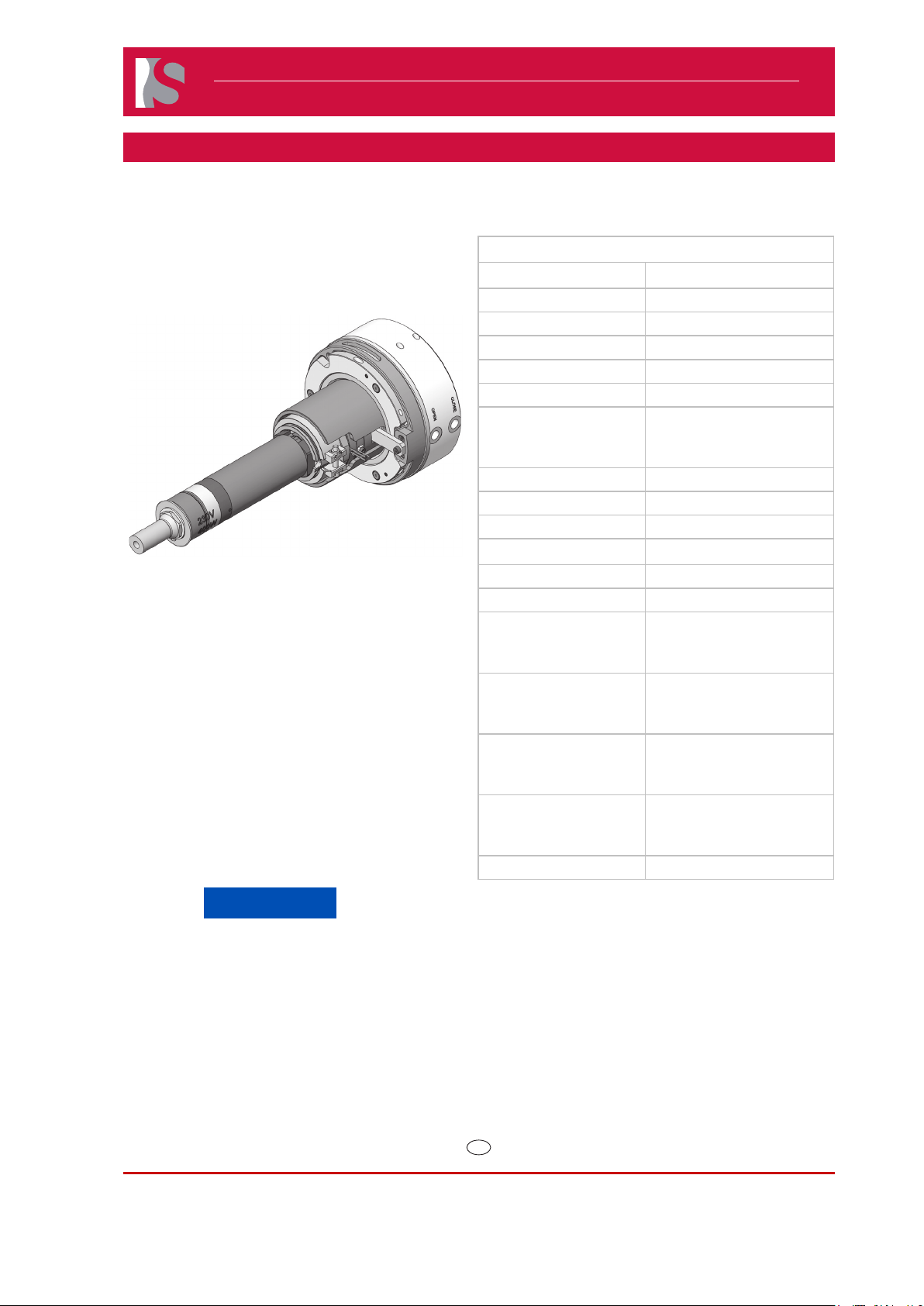
Service and Maintenance / Single Axis Valve Gate Nozzle 16SVH
Safety Instructions for the Service at the Single Axis Valve Gate Nozzle 16SVH
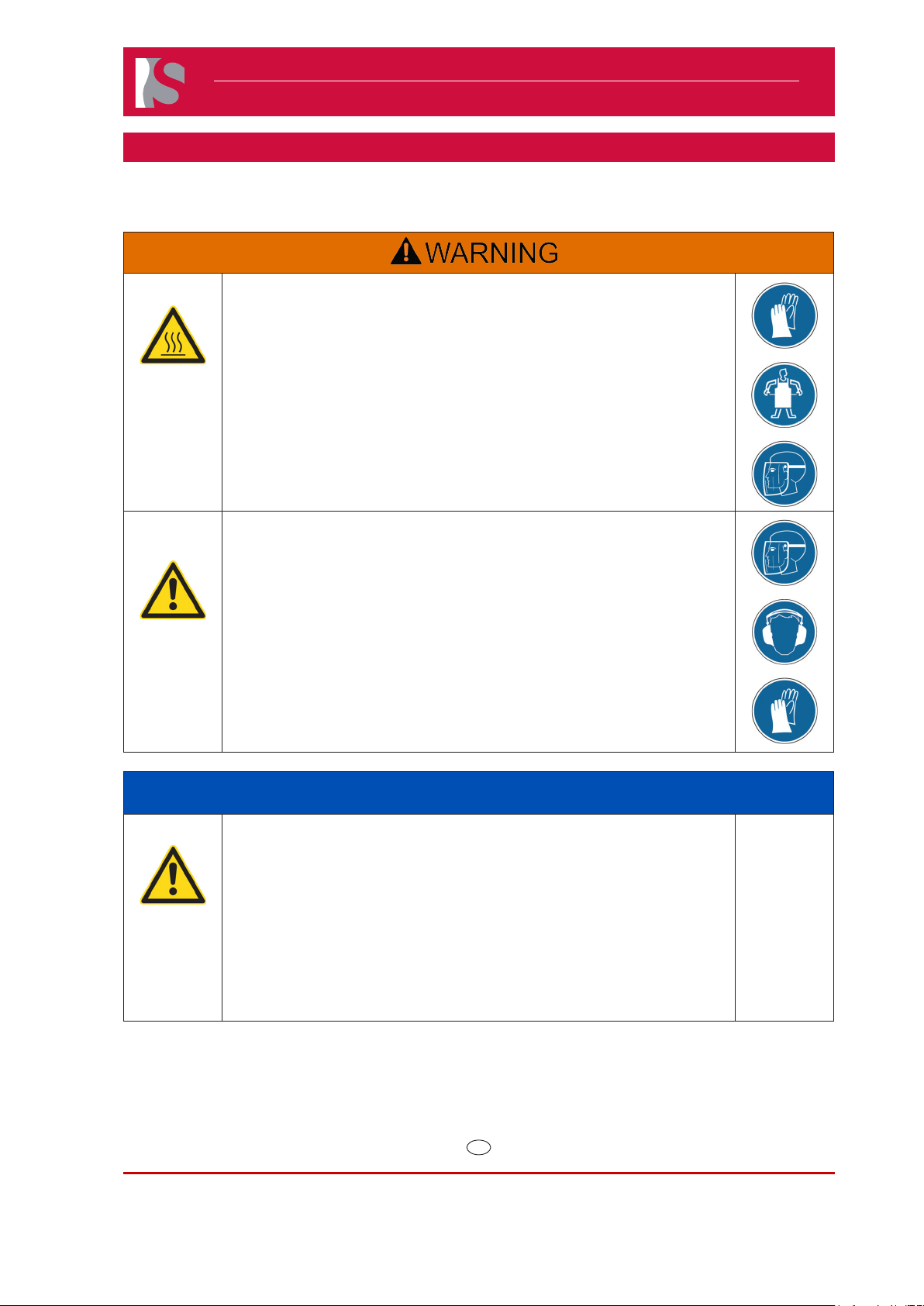
Hot Surfaces Hazard
Contact between the skin and hot surfaces could result in burns.
Use personal protective equipment, such as gloves, apron, sleeves and face
protection, to guard against burns.
When servicing or handling the hot runner system outside the manifold plates
or the injection molding machine, care must be taken to heed the hot surface
exposure warnings.
For rst aid contact your medical / safety representing.
Hazard of Pressurized Air
Pressurized air blow can result in hot plastic or foreign bodies entering the
eyes, causing vision damage.
Following work must be carried out by qualied and experienced persons.
Use personal protective equipment: Face protection, hearing protection and
gloves.
NOTICE
Hazard of Material Damage
Without consulting Synventive it is not permitted to do modications to the
hot runner system e.g. geometrical changes to the nozzle tip, except the part
shape adjustment in the area of material allowance.
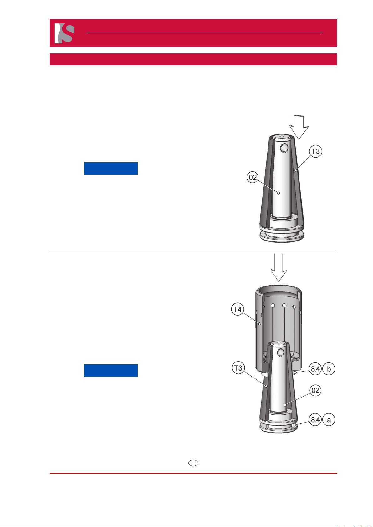
Any impact against the nozzle tip may result in its damage.
Never hammer or impact the nozzle tip from the front (i.e. from the side of the mold).
Twisting could damage the nozzle tip.
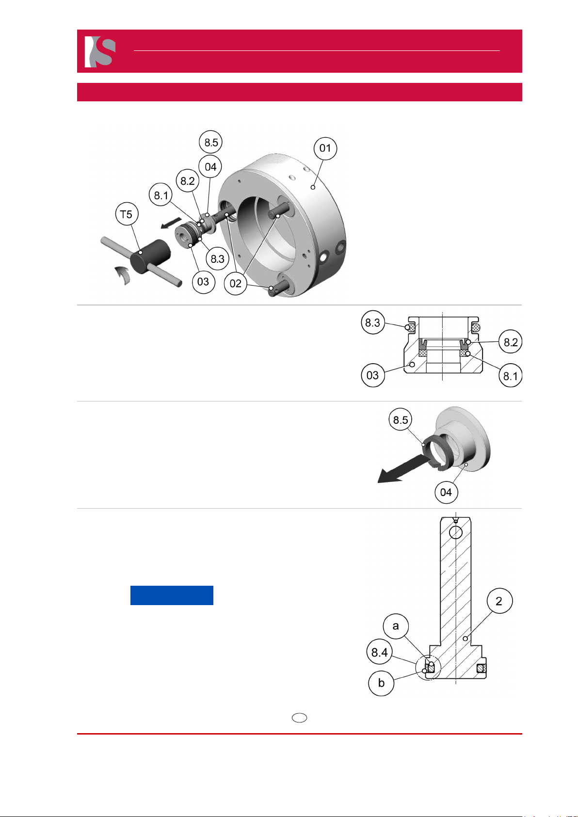
When replacing the nozzles, the sealing rings must always be replaced.