Ecosyl Volac Ecobaler User manual

Ecobaler
Applicator
-1-
DESCRIPTION
The Ecobaler applicator is very versatile and suitable for use with balers or forage harvesters using 1, 2 or 3 nozzles.
It comes supplied to fit 2 nozzles which is sufficient for balers with a 1.5 metre wide pick-up reel. Two nozzles are also
enough for balers with a 2 metre wide pick-up provided they are directed into the area just before the bale chamber
where the width is only 1.5 metres. Three nozzles may be required for square balers due to their faster work rate. An
accessory kit is available to provide the extra nozzle. With forage harvesters it can be used with either 1 or 2 nozzles
depending on their position.
SUPPLIED
1. 250 litre tank with 6 litres/min pump mounted in cradle
2. 9 metres reinforced PVC tubing
3. Fully variable control box
4. Pressure gauge
5. 2 nozzle bodies + set of nozzles
6. 2 brackets with clamps
7. Fitting guidelines/calibration chart/parts diagram
FITTING
The applicator operates from the tractor electrical system, which must have a 12v DC supply. It is important to ensure
that maximum output is being produced by the tractor, otherwise applicator output will be reduced and damage to the
applicator may result.
1. The tank cradle is usually fitted either on the front of the tractor or on the baler itself.
2. The pressure gauge can be fitted in any convenient place between the pump and nozzles as long as it is clearly
visible from the tractor cab. If it is mounted on the baler, uncoupling the baler and tractor is straightforward and
no further joins in the tubing will be required.
3. Fit the control box in an easily accessible place in the tractor cab. Connect the thick black flex to the pump
(red/brown; black/blue) via the spade connectors and the red and black wires to the power supply.
4. Connect the control box to the battery and pump as shown below.
5. Nozzles: For round balers use the bracket and U-clamps provided, position the 2 nozzles about 50 cm apart, 40-50
cm above the pick-up reel. For square balers which have a faster work rate, three nozzles will probably be required
to cover the full width of the pickup. For forage harvesters a single nozzle is usually mounted to spray into the
chopping box or chute although two can be mounted above the pickup. In all cases the aim should be to cover
the full width of the pickup reel, to ensure optimum coverage.
6. Connect the remaining length of cable to the ‘battery’ end of the control box (red to red +ve, black to black -ve).
7. Before using for the first time wash the inside of the tank with a hose to remove any particles that might block the
filter. Remove the water through the drain at the base of the tank.

WARNING: IT IS ESSENTIAL TO ENSURE THAT THE BATTERY LEADS ARE CONNECTED TO THE END OF THE
CONTROL BOX MARKED 'BATTERY' AS WRONG CONNECTION WILL CAUSE DAMAGE.
CONTROL BOX
The applicator is controlled from the tractor cab using the control box. Switch the unit ON/OFF using the switch and use
the round knob to control the flow (see Calibration Chart).
The control box is protected from overload by a 10 amp fuse. Under no circumstances should this fuse be
replaced by any other type of fuse or serious damage could occur, either to the applicator or even to the tractor's
electrical circuits.
OPERATION
1. Select the correct size of nozzle from the Calibration Chart and fit into the nozzle body - ensure it fits tightly. Check
the PVC tubing for damage and that the connections are secure and the right way round (never run the pump in
reverse).
2. Make sure there is some additive in the tank (never run the pump dry).
3. Switch the pump ON at the control box and adjust the variable knob to give the required flow rate (see Calibration
Chart).
OUTPUT
The Ecobaler is capable of up to 6 litres/minute (open flow) provided the electrical supply is adequate. Attachment of
tubing, pressure gauge, nozzles, etc will reduce this.
CALCULATING THE FLOW RATE REQUIRED
Measure the time taken to fill a trailer or make a bale. Only include actual loading time, not time taken turning, etc.
Calculate the flow rate required as follows:
1. Harvest rate (tonnes/min) = weight of grass in trailer or bales (tonnes)
time to fill trailer or make bales (mins)
2. Flow rate (litres/min) = harvest rate (tonnes/min) x required application rate (litres/tonne)
Choose the control box setting in the table below that is closest to the flow rate determined above.
CHOOSING THE CORRECT NOZZLES AND CONTROL BOX SETTING
Do this by choosing the value in the table below that is closest to the flow rate derived from the table above. Then read
off the nozzle size required (Hypro DeflectTip) and the pressure (psi) that will be needed to maintain the correct flow rate.
For example, to achieve a flow rate of 1.6 litres/min using 2 nozzles will require 2 blue DT 1.5 nozzles and a pump
pressure of 15 psi. If more than one nozzle size would provide the correct flow rate, choose the smaller one with the higher
pressure as this will give a more constant flow.
NB. The following table is intended as a guide only - individual calibration should always be carried out..
-2-
CONTROL BOX
APPLICATOR
+
_
POWER
+
POWER
_

WARRANTY
The Ecobaler applicator is guaranteed against failure that can be attributed to faulty workmanship for a period of 12
months from the date of delivery provided that only recommended products are being applied and the recommended
installation and maintenance instructions have been observed. Tampering with the components of the Ecobaler
applicator will invalidate this guarantee. The applicator manufacturer, Team Sprayers, reserves the right to change the
applicator specification at any time without notice to allow for improvements or modifications to its design.
THE WARRANTY IS VOID IF THE APPLICATOR IS USED WITH ACID PRODUCTS.
-3-
MAINTENANCE
1. Always flush out the system with clean water after use. This is especially important at the end of the season.
2. Never allow the pump to stand for long storage periods while filled with additive.
3. Store in a clean, dry place.
4. Never use a higher rated fuse.
5. Do not allow the tubing to become kinked.
TROUBLESHOOTING
Fault Possible causes Remedy
Wires incorrectly connected or damaged Check all connections
Fuse blown Replace fuse. Check for reasons blown before
restarting
Defective motor Contact Team Sprayers
Pump leads wrongly connected Swop connectors
Nozzle blocked Clean nozzle
Tube kinked Remove kink & re-route tubing
Filter blocked Clean filter
Nozzle blocked Clean nozzle
Nozzle too small Replace with larger nozzle
Tubing kinked Remove kink & re-route tubing
Tubing split Replace tubing
Tank empty Fill tank
Wrong nozzle size and/or control box setting
Consult calibration chart – NB. Calibration chart
gives approximate flow rates only - carry out
proper calibration
Control box malfunctioning Contact Team Sprayers
Motor not running
Motor runs but no output
Wrong application rate
Motor runs/poor output
White DT 4.0 5.4 1.8 2.2 2.4 2.8 3.0
Brown DT 2.5 3.7 1.1 1.3 1.5 1.8 1.9
Blue DT 1.5 2.4 0.6 0.8 0.9 1.1 1.1
Green DT 0.75 1.2 - - - - -
Nozzle
Pressure (psi) with 2 nozzles Pressure (psi) with 1 nozzle
3.3
2.2
1.3
0.7
10
4.0
2.6
1.6
0.8
15
4.5
2.9
1.8
0.9
20
4.8
3.2
2.0
1.0
25
5.2
3.5
2.2
1.1
30 35 10 15 20
2.6
1.6
1.0
-
25 30 35
Flow rate (litres/min)

REPAIRS & SPARES
TEAM SPRAYERS LTD, Unit 3, Lancaster Way Business Park, Witchford, Ely, Cambs, CB6 3NW
-4-
For more information on ‘Eco’ Applicators contact:
!
36
27
35
24
2
7
28
26 6
25
14
26
29
17
5
35
23
1
8
7
5
3
13
20
10
12
21
11
39
37
9
19
34
32
30
33
38
16
5
18
5
22
2
00024_Ecobaler_v2 0915
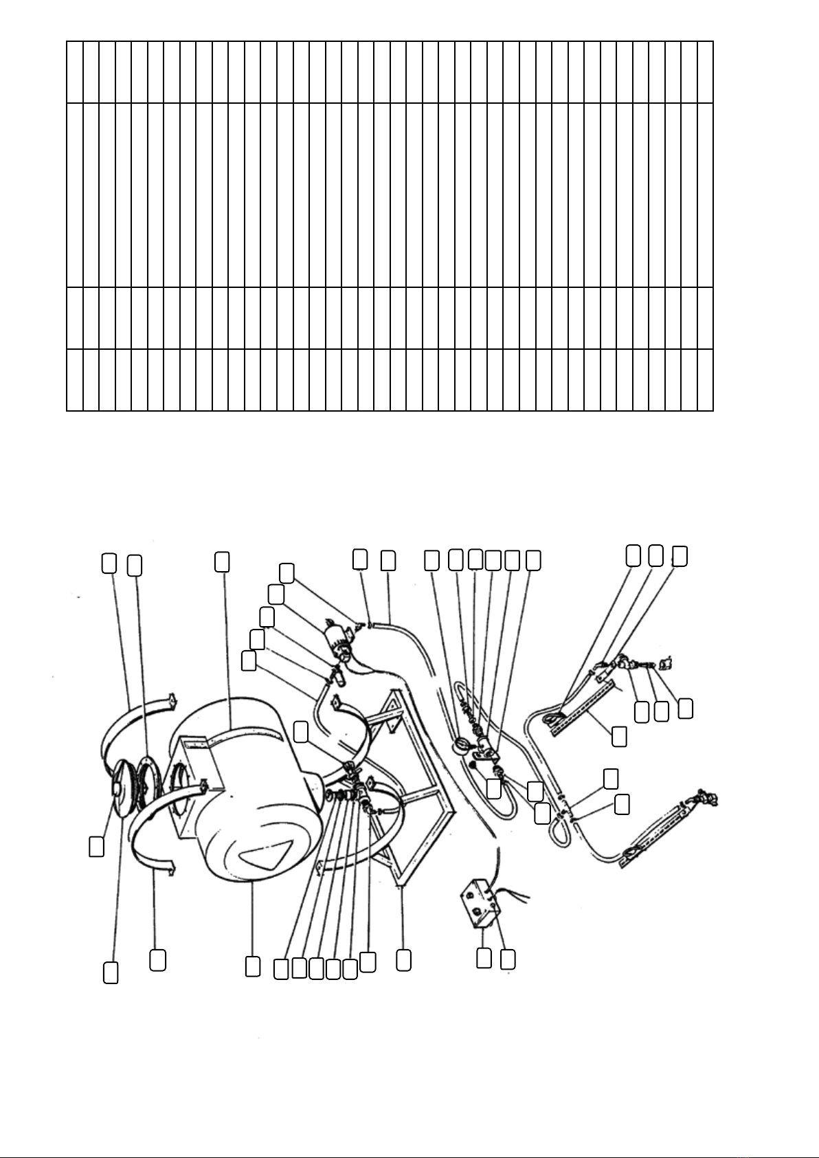
Part No. Description Quantity
1 TS1327 Chassis 1
2 TS1325 Tank strap 2
3 OP0587 10 amp fuse 1
5 OP0204 Hose clip 10
6 OP0310 Drain tap 1
7 OP0317 Hose 9 metres
8 OP0473 Pump 1
9 OP0529 Clamp 2
10 OP0201 Pressure gauge 1
11 OP0525 Tee piece 1
12 OP0526 Male/Male adaptor 1
13 OP0528 Control box (complete) 1
14 OP0530 Plastic spacer 1
15 OP1010 Hosebarb elbow 1
16 OP1073 Hosebarb tee 1
17 OP1118 Hosebarb elbow 3
18 OP1134 Hosebarb 1
19 OP1118 Hosebarb elbow 2
20 OP1162 Nut 1
21 OP1177 Hosebarb 1
22 OP1180 Blanking plug 1
23 OP1197 Filter (complete) 1
24 OP1204 Lid breather 1
25 OP1205 Tank outlet 1
26 OP1206 Gasket 2
27 OP1240 Tank lid (complete) 1
28 OP1241 Neck ring 1
29 OP1246 Tee piece 1
30 OP1271 Tip (green – DT0.75) 2
OP1272 Tip (blue – DT1.5) 2
OP1273 Tip (brown – DT2.5) 2
OP1274 Tip (white – DT4.0) 2
32 OP1031 Nozzle filter 2
33 OP1285 DVC body (complete) 2
35 TS0257 250 litre tank 1
36 TS0995 Contents scale 1
37 TS1328 Bracket 1
38 TS1329 Nozzle arm 2
39 TS1330 Nozzle bracket 2
Spare parts available from:
TEAM SPRAYERS LTD, Unit 3, Lancaster Way Business Park, Witchford, Ely, Cambs, CB6 3NW
-5-
ECOBALER Applicator Parts List
Table of contents
Other Ecosyl Farm Equipment manuals

Popular Farm Equipment manuals by other brands

Skibo
Skibo PEQUEA HT6102 Operator's manual

Titan Attachments
Titan Attachments SS6DOZER72 Operator's manual

REIST INDUSTRIES
REIST INDUSTRIES RR84 Operator and parts manual

Land Pride
Land Pride QuickHitch RBT35 Series Operator's manual

Valley
Valley Rainger Linear owner's manual

Yetter
Yetter 5000 SERIES owner's manual


