Skibo PEQUEA HT6102 User manual

Operator’s Manual
Pequea Turbo Tedder
Model HT6102
THIS MANUAL MUST BE READ AND UNDERSTOOD BEFORE
Manual# 990136
Revised 03/2023
OPERATING THIS MACHINE!

2
COMPLETE YOUR WARRANTY REGISTRATION TO
ACTIVATE YOUR WARRANTY AND TO QUALIFY FOR
PARTS AND SERVICE
To the Owner
Thank-You for choosing a quality product from Pequea Machine, Inc. We
strive to give you the best equipment and the best level of service of any
company. With a little care and maintenance, this machine will do your work
for you for many years. In this manual, we make an eort to get you better
acquainted with the machine so you can achieve maximum performance. We
design and build all of our equipment with the end user in mind so we wel-
come any suggestions or ideas for improvement. Please note that it is within
our rights to make changes or improvements to our equipment without up-
dating the equipment that was manufactured before the change took place.
Please take a few minutes to ll out the area below. This information will be
valuable to you when ordering parts or requesting service from your dealer.
Dealer Name:_____________________________
Dealer Phone Number:______________________
Service Manager/Technician:_________________
Model# and Description:_____________________
Serial Number:____________________________
Date of Purchase:__________________________

1
TABLE OF CONTENTS
Introduction ……………………………………………………………… 2
Intended Use ………………………………………………… 3
Serial Number …………………………………………….… 3
Specications ………………………………………………… 3
Safety …………………………………………………………………….… 4
Power Source Safety ………………………………………… 4
Safety Decals and Reectors ……………………………… 5-6
Folding for Transport ....……………………………………………… 7
Dealer Setup Instructions ....………………………………………… 8
Middle Wheels …………………………………….............… 8
Wheel Lock Links .……………………………….............… 9
Hitching ……………………………………………………………………10
Attaching to the Tractor ……………………………………… 10
Transporting ……………………………………………………………… 11
Field Transport ……………………………………………… 11
Road Transport ……………………………………………… 11
Field Set-up ………………………………………………………………12
Adjustments ………………………………………………………………13
Tine Pitch Adjustment ……………………..………………13
Axle Adjustments …………………………………………..14
Lubrication and Maintenance …………………………………… 15
Gearbox Lubrication ………………………………………… 15
General Lubrication ……………………………………… 16
PTO Shaft Lubrication ……………………………………17-18
Transport Latch Lubrication ………………………………… 19
General Maintenance ……… ………………………………… 20
Wheel Bearings …………………………………………… 20
Electrical ………………………………………………………………… 21
Technical ………………………………………………………………… 22
Replacing the Flotation Springs …………………………… 22
Factory Timing............................ …………………………… 23
Fixing Timing the Outer Rotors……..…………………… 24-27
Warranty …………………………………………………………………… 28

2
INTRODUCTION
At Pequea, we have a strong commitment to ensuring farmers can access the
best agriculture technology in the industry. You put in hard work and long days,
so we do what we can to oer new products that help farms save time, money,
and resources, while increasing their yield. We’ve rened our products over the
years with new upgrades and innovations to treat your land with the respect it de-
serves, using feedback from actual farmers and our engineering team. Whether
you purchase a hay tedder, spreader, trailer, or any of our other ne products,
Pequea – and the agricultural equipment suppliers we work with – are here for
you with the quality you’re searching for to keep your farm running.
Like all Pequea products, we manufacture our leading hay tedders and forage
equipment in our New Holland Pennsylvania facility, using quality components
and expert craftsmanship every step of the way. The TurboTedder stands apart
from other rotary tedders thanks to its round tube arms, carbo-austempered n-
ger joints and asymmetrical tine conguration. All models feature fully enclosed
oil-bath gearboxes, heavy-duty hubs, large tires and a standard tilt cylinder.
Pequea is more than just an agricultural machinery manufacturer. We provide
parts, service, and support for your new equipment. This manual is provided to all
new owners of the Turbo Tedder Model HT6102 to make you aware of all mainte-
nance expectations, safety concerns, and issues you may encounter when own-
ing this piece of equipment. Be sure to keep this manual for future references.
Please review all instructions carefully, taking special note of all safety notica-
tions. Should you have any questions related to your new equipment, please
contact your dealer prior to proceeding. Also, be sure to review the Pequea Ma-
chine’s Limited Warranty and our industry leading Extended Gearbox Warranty,
found on page 28.
Congratulations and Thank You for choosing
Pequea Machine!

3
Intended Use
Pequea TurboTedders are designed for evenly distributing and drying hay crops
only. Pequea will not cover under warranty a tedder that has been used outside
of these crops.
Serial Number
The tedder’s serial number can be found
on the tongue directly under the driveline.
Please use this number when requesting
service, seeking information, or ordering
parts. For the operator’s convenience,
space to record the serial number, model
number, purchase date, and dealer has
been provided inside the front cover of this
manual.
SPECIFICATIONS
Specications HT4102 HT6202 HT6102 HT8101
Transport Width 9’ 2” 9’2” 11’ 0” 11’ 7”
Working Width 18’ 26’6” 26’6” 35’
Number of Rotors 4 668
Arms Per Rotor 7 7 7 7
Arm Construction Round Tubular Round Tubular Round Tubular Round Tubular
Rotor Gearbox Lubrication Grease NLGI #0 Grease NLGI #0 Grease NLGI #0 Grease NLGI #0
Center Gearbox Lubrication 80W-90 Gear Oil 80W-90 Gear Oil 80W-90 Gear Oil 80W-90 Gear Oil
Center Gearbox Capacity 64 oz. 64 oz. 64 oz. 64 oz.
Arm Construction Round Tubular Round Tubular Round Tubular Round Tubular
PTO HP Recommended 35+ 55+ 55+ 75+
Spindle Size 1-3/8” 1-3/8” 1-3/8” 1-3/8”
Hub
4-Bolt w/ Tapered
Bearings
4-Bolt w/ Tapered
Bearings
4-Bolt w/ Tapered
Bearings
4-Bolt w/ Tapered
Bearings
Wheels
4-Bolt Heavy Duty,
Painted
4-Bolt Heavy Duty,
Painted
4-Bolt Heavy Duty,
Painted
4-Bolt Heavy Duty,
Painted
Transport Wheels N/A 18.5 x 8 Load Range D 27 x 7.75 R15 27 x 7.75 R15
Rotor Tires 18.5 x 8 18.5 x 8 18.5 x 8 18.5 x 8
Hydraulic Requirement 1200 psi 1700 psi 1800 psi 1950psi
Figure 1

4
SAFETY FIRST!
This symbol precedes specic safety instructions throughout this manual. When read-
ing the manual, pay close attention to the information that follows this symbol.
FAILURE TO FOLLOW INSTRUCTIONS IN THIS MANUAL COULD RESULT IN PERSONAL
INJURY OR DEATH. READ ENTIRE MANUAL BEFORE OPERATING THE TEDDER.
Keep hands, feet and clothing away from the machine’s power take-o (PTO) shaft and any
other moving parts until the machine has been shut down and the power source has been
locked out.
Do not adjust, unclog, lubricate, or service the tedder until it has been shut down.
Support the tedder securely while working under it.
Be certain all bystanders and animals are a safe distance away before folding or unfolding
the tedder.
Never allow anyone to ride on the tractor or the tedder.
Before transporting, make sure hands-free transport lock is latched in place.
When transporting, never exceed a speed of 25 MPH and avoid sudden turns.
Be constantly aware of the ends of the machine to avoid collision with other objects.
When transporting the machine on public roads, use the proper reectors, lights, and slow
moving vehicle signs required by local government agencies. Pequea will not be liable for any
trac violations.
Be sure to check all fasteners before and after every use. This is especially important when
the tedder is new but is a good practice on any machinery with high vibration levels.
Be careful around hydraulic hoses and ttings. Never go near hydraulic leaks. High pressure
leaks can puncture skin and cause serious injury or death!
Do not attempt to fold the tedder until the machine is on at ground. Folding on uneven terrain
can cause the tedder to ip over.
Power Source Safety
Do not use a PTO shaft without a rotating shield in good working order. Make sure drive sys-
tem safety shields are in place on both the tractor and the tedder.
Do not overextend the PTO Shaft
PTO shield chains must be attached to the tractor and/or the tedder to keep the shield from
rotating.

5
SAFETY
Safety Decals and Reectors
Safety decals and reectors are for the safety of yourself and others, and must
be heeded at all times. If any decals are missing, faded, or damaged in any way,
please contact your dealer for replacements immediately. Shown below are some
of the decals used on your tedder.

6
Stay Clear of Rotating Drivelines
TS1644-UN-22AUG95 H96219-UN-29APR10
Entanglement in rotating driveline can cause serious injury or death.
Keep tractor master shield and driveline shields in place at all times. Make
sure rotating shields turn freely.
Wear close fitting clothing. Stop the engine and be sure that PTO driveline
is stopped before making adjustments, connections, or cleaning out PTO
driven equipment.
Do not install any adapter device between the tractor and the primary
implement PTO drive shaft that will allow a 1000 rpm tractor shaft to power
a 540 rpm implement at speeds higher than 540 rpm.
Do not install any adapter device that results in a portion of the rotating
implement shaft, tractor shaft, or the adapter to be unguarded. The tractor
master shield shall overlap the end of the splined shaft and the added adaptor
device as outlined in the table.
PTO Type
Diameter Splines
n ± 5 mm (0.20 in.)
1 35 mm (1.378
in.)
6 85 mm (3.35 in.)
2
35 mm (1.378 in.)
21 85 mm (3.35 in.)
3
45 mm (1.772 in.)
20 100 mm (4.00 in.)
SAFETY
7
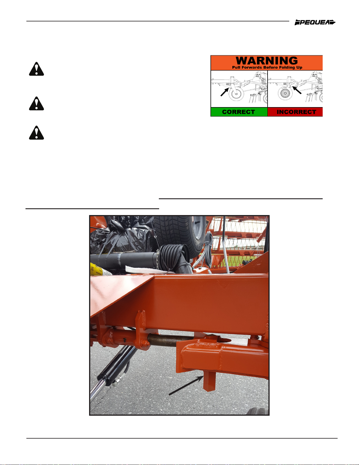
When tedding, the transport wheels can swivel and are spring loaded to support
the weight of the chassis. The springs will be compressed and the wheels locked
in the straight position when the tedder is folded up for transport. Figure 2 shows
the transport lock properly engaged. Do not transport the tedder until transport
lock is latched in place as shown.
Figure 2
Do not fold for transport unless the tedder is
on even ground. Folding on uneven ground
can cause the tedder to tip over.
Transport Lock Engaged
FOLDING FOR TRANSPORT
Pull forward with the tractor before folding.
This will straighten the wheels & position them
ready for folding up.
Be sure to have the wheels relatively straight before folding so the locks can en-
gage properly!

8
DEALER SETUP INSTRUCTIONS
Middle Wheels
The Middle Wheel frames are stored on the
Transport Arms for shipping. Unbolt the wheel
frames from the transport arm. Install onto the
rotor spindle casting with the “U” spindle to-
wards the center of the tedder. When Finished,
the tedder should look like shown in below in
Figure 4. The spindles should have alternating
directions. The hay movment between the ro-
tors when tedding should be in the open area-
between the wheels where there isn’t a spindle.
Figure 3
Figure 4

9
Wheel Lock Links
The Links for the wheel locks are positioned into
black forklift plates when the tedder arrives at
the dealer (Figure 5). This is so that the forklift
doesn’t bend the link arms when picking up. After
unloading the tedder, it is necessary to move the
link arms by removing the zip ties and securing
on the 3/4” bolt. The swivel eye on the link arm is
to be installed inbetween the two spacer wash-
ers as shown in gure
Place ring washers on
either side of ball
swivel.
Figure 6
Figure 5

10
HITCHING
Attaching to the Tractor
Figure 7
Crank the jack up or down to align the tractor draw bar with the hitch.
Figure 8
The tedder hitch is bolted on and can be adjusted up or down to accommodate various drawbar
heights (Figure 7). Select a height that keeps the tedder chassis level when it is connected to
the tractor.
When attaching to the draw bar always use a draw bar pin with a safety clip to ensure that the
tedder doesn’t bounce o of the tractor.
After attaching the tedder, crank the jack down until all the weight rests on the tractor drawbar,
then remove the jack and place it in the transport position. (Figure 8)
Attach the PTO shaft to the tractor. Make sure the locking balls in the splined coupling are oper-
ational and that the PTO shaft locks securely on the tractor output shaft. NOTE: Be sure to push
the PTO stand down against the tongue to avoid damage to the PTO shaft shielding.
The HT6102 is equipped with hydraulic cylinders to fold the machine for transport. The hoses
should be connected to a double acting valve at the rear of the tractor. The slotted holes on the
side of the tongue (Figure 7) are storage holes for the hoses
If your tedder is equiped with the lighting package option, you will need to connect the wiring
plug from the tedder into the female plug end on the tractor. Never travel on public roads without
proper lighting.

11
TRANSPORTING
Field Transport
Never allow any riders on the tractor or the tedder.
Remain fully aware of the width of the tedder in relation to objects you are passing.
Never travel at speeds of more than 12 MPH in the eld.
Road Transport
Adhere the suggestions for eld transport listed above.
Make sure the hands-free transport lock is latched in place properly (shown in Figure 2-pg 7).
ALWAYS FOLLOW LOCAL TRAFFIC LAWS IN REGARDS TO THE TRANSPORTING OF FARM
EQUIPMENT. PEQUEA WILL NOT BE HELD LIABLE FOR FINES INCURRED DUE TO TRAFFIC
VIOLATIONS.
Do not exceed 25 MPH on any public road. Excessive speeds combined with common road obstruc-
tions can cause failures.
Figure 9 Figure 10
Be sure the SMV (slow moving vehicle) Symbol is visible from the rear of the machine, as shown in
Figure 9.
Keep a close eye on the tedder wings when transporting on the road or in the eld. A leaky valve
in the tractor’s hydraulic system will cause the tedder to slowly unfold. If this occurs, you will want
to disconnect the hydraulics before transporting. Figure 10 shows the wings supported properly for
transport and the safety chains attached.
Be sure to use the lights when traveling on the road at night.

12
FIELD SET UP
To lower the tedder into tedding position, engage the hydraulics for the tilt cylinder rst to raise the
wings o of the chassis then engage the main hydraulics to unfold the wings. Be sure that nobody
is around the tedder or the tractor as the wings are lowering. The tines and arms can cause serious
injury to anybody that it comes into contact with. Make sure that the hitch is attached to the tractor
and the pin is installed when the wings are lowering. If the hitch is not properly attached to the trac-
tor, the weight of the rotors when it is unfolding could cause the hitch to whip up causing serious
personal injury or damage to equipment.
1-2”
NEVER RUN THE PTO WHILE THE TEDDER IS IN THE TRANS-
PORT POSITION! THIS CAN CAUSE DAMAGE TO THE JOINTS
AND ALSO POSES A PERSONAL INJURY HAZARD.
DO NOT ADJUST THE TEDDER UNLESS THE TRACTOR IS OFF AND THE PTO SHAFT
IS DISCONNECTED. ALWAYS ADJUST THE MACHINE BY YOURSELF. A SECOND
PERSON INCREASES THE CHANCE OF AN ACCIDENT.
The tine height adjustments can be made by turning the handle shown in Figure 11.
Turn the handle clockwise to raise the tine height.
Turn the handle counter clockwise to lower the tine height.
Generally, the tines should be around 1-2 inches from the ground for most crops (Figure
12). However, the stubble length or crop moisture content can change where the optimum
setting will be.
IT IS UP TO THE OPERATOR TO DETERMINE WHAT THE BEST POSITION SHOULD
BE.
Figure 11
Figure 12

13
ADJUSTMENTS
Tine Pitch Adjustments
Figure 13 Figure 14
Figure 16
Figure 15
The tine pitch (the angle of the tine in relation to the tine arm) can be adjusted
by reversing the eccentric spacer washer. The spacer position in Figure 13 will
give the tine a less aggressive position as shown in Figure 14.
The spacer position shown in Figure 15 will give the tine a more aggressive
position as shown in Figure 16.
A more aggressive tine position will throw the hay higher.

14
Axle Adjustments
The angle of the axles can be adjusted to raise
or lower the whole machine. This will allow you
to tilt the tedder forward more and get a more
aggressive tedding action. The tedders are set
at the factory to run in the middle setting (shown
at right). To adjust to the higher position you will
need to pick the tedder up o the ground using
a hoist or a lift. With the tedder’s weight sup-
ported properly with blocks, remove the 1/2”
bolt, pull the axle forward to meet the second
hole, and reinsert bolt. Repeat the process for
all the axles. The setting hole “1” corresponds
to the most aggressive angle. Setting “3” is the
least aggressive angle.(Figure 17) Figure 17
DO NOT BEGIN OPERATION UNTIL ALL OF THE SAFETY WARNINGS HAVE
BEEN READ AND UNDERSTOOD!
Once all of the adjustments and initial set up instructions have been followed and the proper ad-
justments made, the tedder is ready to operate in the eld.
Connect the tedder PTO shaft to the tractor by pulling the spring collar back and sliding the shaft
yoke onto the 6 splined tractor PTO shaft. Slide the shaft forward until it stops and then pull back
slowly until the balls engage into the ball groove on the tractor shaft.
DO NOT RUN THE PTO UNLESS THE LOCKING BALLS ARE ENGAGED. THE SHAFT COULD
SLIDE OFF DURING OPERATION AND CAUSE SERIOUS INJURY OR DEATH.
The PTO speed should never exceed 540 rpm. Generally, 450 rpm and a 6 mph ground speed
is a comfortable operating setting. Crop conditions and eld conditions will ultimately determine
the settings for the tedder and the tractor.
GENERAL OPERATION
1
2
3

15
LUBRICATION AND MAINTENANCE
NEVER PERFORM ROUTINE MAINTENANCE, REPAIRS OR INSPECTIONS ON ANY PIECE
OF EQUIPMENT UNLESS THE TRACTOR IS SHUT OFF AND DISCONNECTED FROM THE
MACHINE.
IT IS ALWAYS BETTER TO WORK WITH ANOTHER PERSON WHEN MAINTAINING OR
SERVICING A PIECE OF EQUIPMENT. ACCIDENTS CAN BE PREVENTED AND HELP CAN
BE ATTAINED EASIER WHEN ANOTHER PERSON IS AVAILABLE TO HELP.
Gearbox Lubrication
The oil in the center gearbox should be drained out and replaced every year. Be-
fore Servicing, make sure that the tedder is on level ground and the wing tunnels
are level. The tilt cylinder will need to be adjusted. The purpose is for leveling is
for accuracy when using the check plug.Take out the Drain Plug and drain all of
the oil. When relling the gearbox use approximatly 64 oz of 80W-90 gear oil.
Remove the ll plug and the check plug. Then ll up until oil comes to the bottom
of the check plug hole. Then put all plugs back in place with pipe sealing teon
tape. Check the oil level periodically throughout the season to ensure that it re-
mains full at all times.
Be sure to properly dispose of any used
oil or grease! Do not pour directly onto the
ground!
Figure 18
OIL FILL PLUG
OIL DRAIN PLUG
CHECK PLUG

16
Figure 19
The rotor gearboxes (Figure 19) have been
packed with grease at the factory and should not
need to be maintained. However, they should
be checked before each season to make sure
the gears are still coated with a lm of grease. If
additional grease is needed, use several ounc-
es of NLGI #0 gear grease.
All of the pivot points have a grease
tting and a bronze bushing. This
should always be visibly wet with
grease. Grease as needed.
General Lubrication
When a grease point has specic hourly frequency, 1 full pump each time should
be sucient lubrication. Always use a NLGI#2 grease that is rated for high tem-
peratures commonly found in a bearing.
The cylinder nut should always be vi-
sually wet with grease. Grease as
needed.
Figure 20
Figure 21
LUBRICATION AND MAINTENANCE

17
The radial pin clutch on the primary
driveline should be greased every 50
hours. Do not overgrease the radial
pin clutch.
PTO Shaft Lubrication
Figure 22
Figure 23
Grease the CV Joint (part
that connects at tractor)
every 50 Hours (3 loca-
tions)

18
The plastic PTO shielding
should be lubricated at all times.
If the shield feels tight when it is
extended and retracted then lu-
bricate as necessary.
The center cross in all of the
PTO yokes should be greased
every 50 hours.
Figure 24
Figure 25
LUBRICATION AND MAINTENANCE
Table of contents
Other Skibo Farm Equipment manuals


Popular Farm Equipment manuals by other brands

Schaffert
Schaffert Rebounder Mounting instructions

Stocks AG
Stocks AG Fan Jet Pro Plus 65 Original Operating Manual and parts list

Cumberland
Cumberland Integra Feed-Link Installation and operation manual

BROWN
BROWN BDHP-1250 Owner's/operator's manual

Molon
Molon BCS operating instructions

Vaderstad
Vaderstad Rapid Series instructions


