Ecotech DW 45 Instruction manual

INTERRAFILO PROFESSIONALE DOPPIO CAVO
PROFESSIONAL DOUBLE-WIRE LAYERING MACHINE
MACHINE ENFOUISSEUSE DOUBLE CÂBLE PROFESSIONNELLE
PROFESSIONELLE KABELVERLEGUNGSMASCHINE MIT DOPPELTEM KABEL
ENTERRADOR DE CABLES PROFESIONAL DOBLE CABLE
PROFESSIONELL KABELLÄGGARE FÖR DUBBEL KABEL
KAAPELINLASKUKONE KAHDELLE KAAPELILLE AMMATTIKÄYTTÖÖN
PROFESJONALNA MASZYNA DO JEDNOCZESNEGO UKŁADANIA DWÓCH KABLI PODZIEMNYCH
PROFESSIONAALNE TOPELTKAABLI PAIGALDUSMASIN
MODELLO - MODEL - MODÉLE - MODEL – MODELO - MODELL - MALLI - MODEL - MUDEL DW45
• MANUALE DI USO E MANUTENZIONE
• MANUAL FOR USE AND MAINTENANCE
• MANUEL D’UTILISATION ET DE MAINTENANCE
• HANDBUCH ZUR VERWENDUNG UND WARTUNG
• MANUAL DE USO Y MANTENIMIENTO
• HANDBOK FÖR ANVÄNDNING OCH UNDERHÅLL
• KÄYTTÖ- JA HUOLTO-OHJE
• INSTRUKCJA OBSŁUGI I KONSERWACJI
• HOOLDUS- JA PAIGALDUSJUHEND
Revision Date Description
0 24/09/2019 Issue
IT ‐ EN ‐ FR ‐ DE ‐ ES ‐ SV ‐ FI – PL ‐ EE

ENGLISH
2
IMPORTANT!
This machine has been manufactured according to CE standards and is certified by the related marking
Throughout this manual and on the machine are given indications and captions
below that indicate a potential danger. It is, therefore, recommended to pay particular attention to the
warnings (be it image or message) to ensure greater safety for the operator and anyone present within the
operation area of
the machine.
DESCRIPTION OF THE SYMBOLS
It is advisable to read this user’s manual before starting up the machine and starting the works.
Wear the personal protection
equipment required.
WARNING!!! The fuel is highly flammable; handle it with particular care and caution.
It is strictly forbidden to fill the fuel tank while the engine is running, or while smoking, or in the presence of
flames
or sparks.
While running, the machine could eject gravel, pieces of grass or other objects.
To avoid damaging third parties, before using the machine the operator must ensure no one is present in an
area
of at least 20 meters around the machine.
IMPORTANT!
This machine has been manufactured according to CE standards and is certified by the related marking
Throughout this manual and on the machine are given indications and captions
followed by the danger sign
below that indicate a potential danger. It is, therefore, recommended to pay particular attention to the
warnings (be it image or message) to ensure greater safety for the operator and anyone present within the
the machine.
DESCRIPTION OF THE SYMBOLS
It is advisable to read this user’s manual before starting up the machine and starting the works.
equipment required.
WARNING!!! The fuel is highly flammable; handle it with particular care and caution.
It is strictly forbidden to fill the fuel tank while the engine is running, or while smoking, or in the presence of
or sparks.
While running, the machine could eject gravel, pieces of grass or other objects.
To avoid damaging third parties, before using the machine the operator must ensure no one is present in an
of at least 20 meters around the machine.

ENGLISH
3
The machine is equipped with a rotary cutting component. Never get the hands and feet near it!!!
Dangers list label applied on the machine, clearly visible
WARNING!!! The machine is equipped with an extremely powerful cutting component, therefore keep the
hands and feet away from it and never work on the machine while the engine is running.
It is recommended to avoid laying cables on areas containing gravel, stones and foreign bodies of various types
since they can be ejected by the cutter, thus being extremely dangerous to the persons or things nearby. Keep
the persons at least 20 meters away from the machine. The operator must wear a safety mask on the face and
possibly also rubber boots.
WARNING!!! Never get your hands near the swing mechanism fitted on the machine; this mechanism can
crush the fingers.
N.B. FOLLOWING THESE SAFETY RECOMMENDATIONS IS NOT A
WASTE OF TIME!
THEY HELP YOU AVOID IRREPARABLE DAMAGE TO PERSONS OR THINGS AND ENSURE
THE OPERATOR’S SAFETY.
CE IDENTIFICATION PLATE OF THE MACHINE.

ENGLISH
4
DW 45 – PROFESSIONAL TWO‐CABLE LAYER
Dear Customer, thank you for having chosen ECOTECH Italy; we trust your new machine matches
fully our needs. To optimize the use of the cable layer and for an effective maintenance over time,
please read all signs and recommendations described in this manual, which must be preserved and
must always accompany the machine. READ CAREFULLY THE INSTRUCTIONS FOR USE BEFORE
USING THE MACHINE!
GENERAL SAFETY RECOMMENDATIONS
Always use the machine with extreme caution.
Read this manual carefully prior to starting to use the machine.
The machine features several safety labels: make sure to follow them! The warning labels
remind the operator the possible damages implied by the
improper use of the machine. Therefore, pay always particular attention to the meaning
of such warning signs.
The machine is equipped with a rotary element consisting of an extremely sharp steel cutter.
KEEP AWAY THE HANDS AND FEET FROM THE CUTTING ELEMENT!!!
Should the machine be used by other people, make sure they are aware of the safety rules and of
the instructions for use.
Before starting to work, make sure there are no objects on the ground that could get ejected by
the machine and become extremely dangerous to anyone nearby.
Keep people, animals or things at least 20 meters away from the machine. To avoid being hit by the
objects ejected, the operator must wear: SAFETY MASK FOR THE FACE, OVERALLS, BOOTS, GLOVES,
CAP.
Never perform maintenance on the machine while the engine is running.
IT IS COMPULSORY TO STOP THE ENGINE BEFORE PREFORMING MAINTENANCE OPERATIONS.
Do not tamper with or disable the safety devices.
The operator is held liable for damages caused to third parties.
In case the operator uses the machine other than according to the permitted use, the warranty is
voided and all liabilities declined.
Should you identify a fault on the machine while using it, contact the service centre of the dealer
who sold you the machine.
NEVER TRY TO REPAIR THE MACHINE YOURSELF. LACK OF EXPERTISE CAN WORSEN THE DAMAGE.
Always use original spare parts supplied by the manufacturer.

5
Fig.1
1. Fuel tank cap
2. Engine starting contactors
3. Gas lever
4. Cutter adjuster
5. Forward motion adjuster
6. Cutter start lever
7. Handlebar oscillation control lever
8. Oscillation control adjuster
9. Forward motion lever
10. Cable winder
11. Engine oil plug
12. Blade scrapper
ENGLISH

ENGLISH
6
INSTRUCTIONS FOR USE
Prior to starting the engine and beginning to work, make sure to perform the checks listed below:
• Check the integrity of the cable outlet spout on the cable laying blade (Fig. 2). Check in
particular the integrity of the hose inside of the blade. If damages are found, replace it. Also
check that there are no cuts along the entire edge of the blade spout; make sure the edge is
not sharp or jagged. Replace the blade if damaged.
Fig. 2
• Make sure the oil level has not lowered below the minimum: unscrew the cap (fig.1 n.11),
clean the dipstick with a rag then tighten back the plug. Unscrew again and make sure the oil
level stays between the minimum and maximum level notches. Should the level be below the
minimum limit, top up the oil to the optimum level. (require the suitable oil type to your
dealer).
WARNING!!! THE MACHINE IS SUPPLIED WITH NO OIL
• Make sure that all screws are properly tightened.
• Check that all levers are placed in neutral position (fig.1 n.6/n.9).
• Clean the air filter if there are impurities (check the booklet of the engine).
• Fill the machine with fuel using a funnel provided with filter.
• Open the fuel tap (check the booklet of the engine).
• To start the engine when cold, position the gas lever (fig.1 n.3) to
START.
• Grip the engine starting knob (fig.1 n.2) and pull forcefully.
• Wait a few minutes to reach the operating temperature before setting it to the
maximum speed.
IT IS RECOMMENDED TO ALSO FOLLOW THE INSTRUCTIONS DESCRIBED IN THE ENGINE BOOKLET.
Before starting to work, place the cable into the cable winder, adjust the burial depth, tie the cable
end to a stake, make sure there are no people, animals or things at least 20 meters around the
machine, then start the engine and, once it has warmed up, start operation. Lower completely the
cutter rotation clutch (fig.1 n.9),
engage it to fully forward (fig.1 n.1) and start working by always paying utmost attention. Read
carefully the description of the operations given below.
During the summertime or in the presence of dry soil, it is recommended to abundantly water the
ground the day before performing the work.

7
THE MACHINE MUST BE RUN-
IN! DURING THE FIRST OPERATION HOUR THE BELTS WILL SETTLE.
MAKE SURE THE STRETCHING SPRINGS WORK PROPERLY
(fig.1 n.4/n.5).
ASSEMBLING OR REPLACING THE BLADE
The blade of the cable layer consists of various parts to be assembled be
to fasten it to the machine. The assembling diagram is shown in Fig. 3.
Fig. 3
On the structure of the blade must be inserted, in order: the sealing ring, the spacer and the
threaded bushing. With the bushing slightly
loosened, enter the hose until it comes out from the
lower part of about 5 mm. At this point, tighten the threaded bushing using a wrench n. 17 and then
lock the hose. Complete the assembly of the left and right cable holding guides. The Fig. 4 shows
the b
lade correctly assembled. Now you can fasten the blade to the structure of the machine.
POSITIONING THE CABLE IN THE WINDER
Given the variety of cable types and of reel types available
on the market, the machine has been equipped
with a removable
clutched cable winder. The cable can be wrapped into the cable winder (fig.1
n.10) using the lever provided on the winder. It is important
to wrap the cable clockwise so that during the work it
can be smoothly unwinded (fig. 5). If you wa
nt to use one of the
cable reels already wrapped, remove the winder by loosening
the knob (fig.6-A) and pull the retainer (fig.6-
B); remove the winder
(fig.6-
C), position the reel on the tube of the winder and use the
adapters (fig.6-D) if necessary, then
fit back the retainer and tighten completely the
knob (fig.6-E).
Once the cable has been positioned in the winder, enter the cable end in the tube
of the blade (fig. 7-
A) until it comes out from the bottom a few
ENGLISH
IN! DURING THE FIRST OPERATION HOUR THE BELTS WILL SETTLE.
The blade of the cable layer consists of various parts to be assembled be
fore proceeding
to fasten it to the machine. The assembling diagram is shown in Fig. 3.
Fig. 4
On the structure of the blade must be inserted, in order: the sealing ring, the spacer and the
loosened, enter the hose until it comes out from the
lower part of about 5 mm. At this point, tighten the threaded bushing using a wrench n. 17 and then
lock the hose. Complete the assembly of the left and right cable holding guides. The Fig. 4 shows
lade correctly assembled. Now you can fasten the blade to the structure of the machine.
Given the variety of cable types and of reel types available
with a removable
clutched cable winder. The cable can be wrapped into the cable winder (fig.1
n.10) using the lever provided on the winder. It is important
nt to use one of the
cable reels already wrapped, remove the winder by loosening
B); remove the winder
C), position the reel on the tube of the winder and use the
fit back the retainer and tighten completely the
Fig.5
Once the cable has been positioned in the winder, enter the cable end in the tube
A) until it comes out from the bottom a few
centimetres (Fig. 7-B).

8
ENGLISH
A B C D E
Fig.6
A B
Fig.7
ASSEMBLING OR REPLACING THE CUTTER
Make sure to have at hand a 6 mm spanner.
To assemble or replace the cutter, unscrew the retaining screw of the head (fig.8-A),
remove the worn cutter if already fitted to the head (fig.8-B) and insert the new cutter. Tighten
completely the retaining screw. If the cutter is replaced while working, make sure to clean thoroughly
the head by removing the residues of grass and dirt; ensure no residues enter the cutter
during the installation of the new one. It is recommended to clean and grease the housing
of the cutter each time the machine has been used (check “CLEANING THE HEAD”).
A B C
Fig.8
HOW TO ADJUST THE BLADE CUTTING DEPTH
To adjust the depth, act on the knob fitted
on the rear of the blade (fig.9-1). Loosen the knob a few turns
counter-clockwise, raise or lower the support of the two rear wheels (fig.9-
3) using as depth reference the graduated bar placed
on the support side (fig.9-2); once the necessary depth has been reached,
tighten completely the knob (fig.9-1) by rotating it clockwise. The numbers
on the graduated bar correspond to centimetres and range from 1 to 6.
Fig. 9
SPEED CONTROL
To adjust the cutting speed, act on the accelerator knob (fig.1 n.3) and
increase or decrease the engine rotations. Never adjust the speed by slipping slightly the clutch discs

ENGLISH
9
of the transmission box. This operation can severely damage the mechanical part
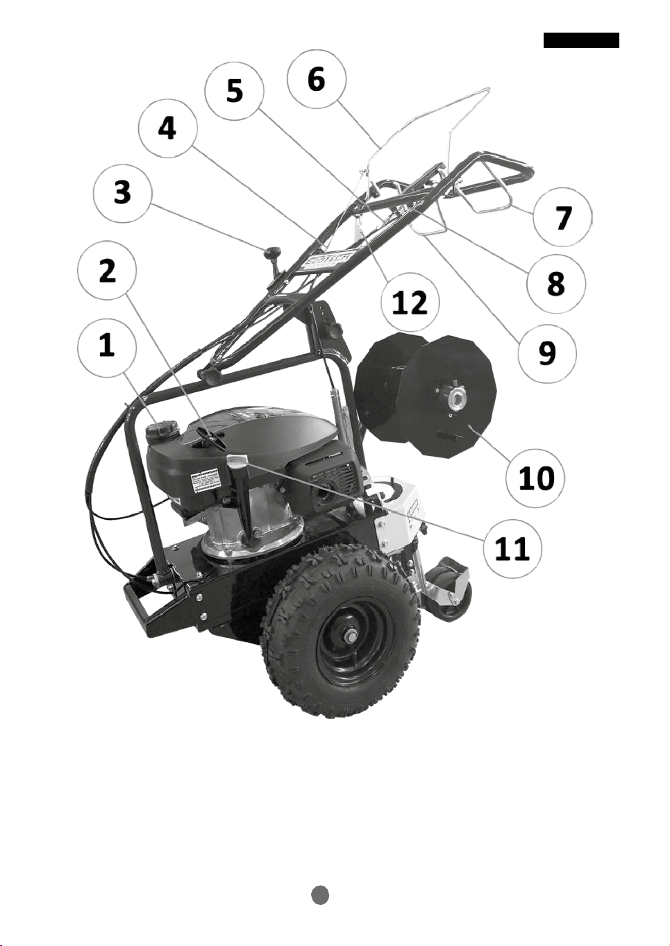
of the transmission. The forward lever (fig.1 n.9) must ALWAYS be pulled completely, i.e.
until it touches the handle.
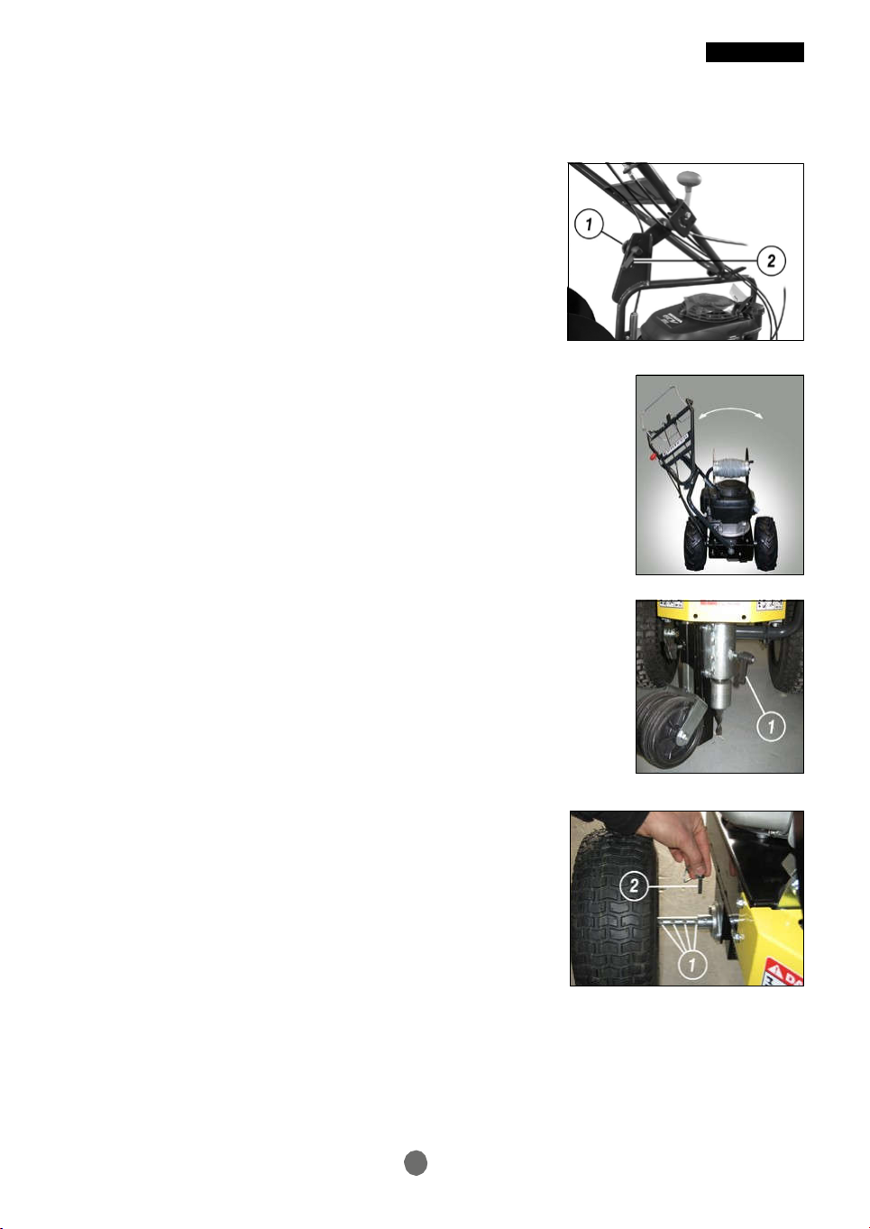
HOW TO ADJUST THE HEIGHT OF THE HANDLEBAR
The handlebar of the machine can be adjusted on five heights. To adjust
the height, loosen counter-clockwise the rear handle of
the handlebar (fig.10 n.2) until the knob (fig.10 n.1) can be removed, select
the height of interest, then fit back the knob in the new hole, rotate
clockwise and tighten completely the handle.
Fig.10
HOW TO ADJUST THE HANDLEBAR INCLINATION
In case of works under hedges, projecting branches, posts or any
type of obstacle, it is possible to tilt the handlebar from the opposite side
of the obstacle (fig. 11). To adjust the inclination, pull completely the lever placed
on the lower left side of the handlebar (fig.1 n.7) and position
the corresponding pin in one of the nine holes located on the rack at the bottom
of the handlebar. The machine allows four inclination levels
on the right and four on the left.
Fig.11
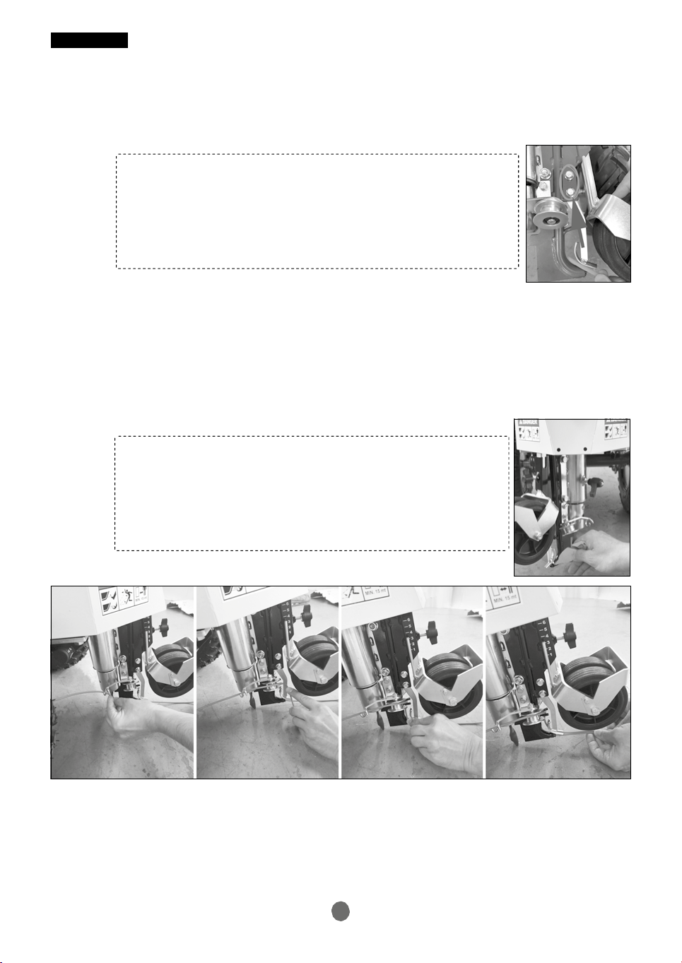
HOW TO LOCK THE SWIVELLING BLADE
When the cable has to be laid over long straight sections, it is
possible to lock the swivelling blade (fig.12) to ensure greater
precision of the machine direction. To lock the blade, it suffices to tighten the handle
placed on the right side of the support apparatus (fig.12 n.1).
Fig. 12
HOW TO ADJUST THE WIDTH OF THE WHEELS
Both wheels are equipped with 4-position adjustable drive shafts.
This system offers the possibility to position the cutter
at 25, 27, 29 o 31 cm from the adjustable edge.
(fig.13). This allows laying the cable at equal distance
from any edge, wall or hedge. To adjust this
distance, pull out the locking pin (fig.13 n.2), position it
in one of the 4 holes provided on the drive shaft (fig.13 n.1) and
lock back the safety spring.
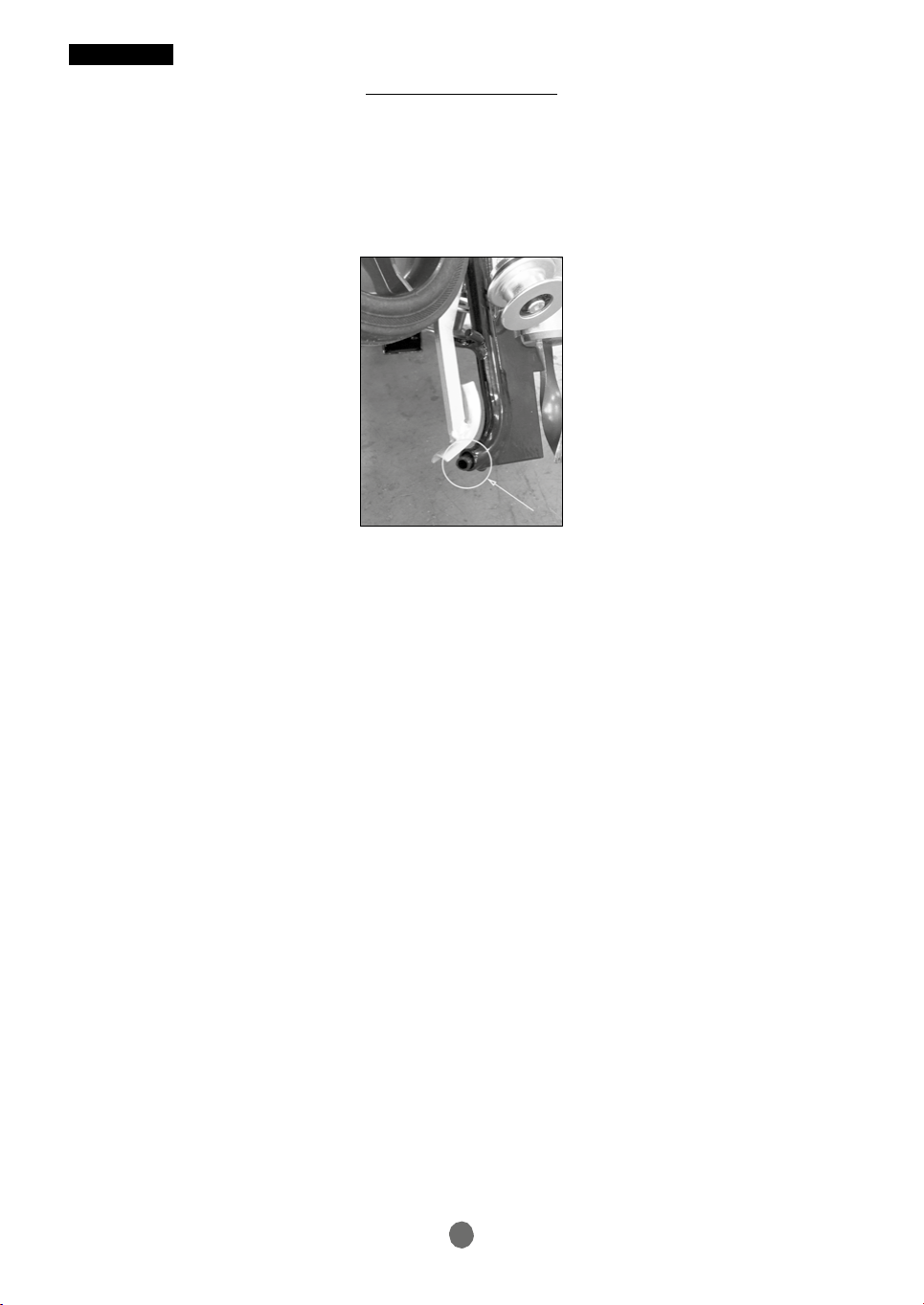
HOW TO START WORKING
Fig.13
Once the cable is positioned and the cutter is mounted, fix the cable to the ground. To do so,
stick a bit or a stake into the ground and fasten to it the part of the cable that
comes out from the bottom of the blade. This operation has the purpose to ensure the cable
is laid on the furrow created by the cutter on the soil along the first few meters.

10
ENGLISH
HOW TO USE THE TWO‐CABLE BLADE
Laying two cables at the same time is required when it is necessary to go around trees,
flowerbeds, etc. (islands) away from the outer perimeter of the workspace. Proceed as follows (check
the sequence given in Fig. 15):
ADJUSTING THE BLADE DEPENDING ON THE CABLE THICKNESS
The machine is adjusted for 4 mm cables. To use
a cable having greater diameter, loosen the
two screws shown in the figure and raise the blade part a few millimetres.
Fig. A- B: proceed normally by ploughing one cable along the entire perimeter
Fig. C: once you have reached the point indicated in the figure, extract the blade from the soil, fasten
the cable with a stake and continue with the cable over the soil up to the next point.
Fig. D: in the point indicated in the figure, fasten the cable again on a stake
Fig. E: continue by normally ploughing the cable to create the island
Fig. F: once you have reached the point indicated, remove the stake previously fixed, and clean
the blade; fit the cable above ground in the blade as per the sequence (Fig. 14) below:
CLEANING THE BLADE
The cable laying machine is provided with a suitable tool (Fig.1-12
blade scraper ) for the cleaning of the soil residues which obstruct
the blade. Use it according to the image on the side.
Fig. 14
Fig. G: plough the two cables at the same time up to the point indicated in the figure. Fasten to a
stake the two cables and unhook the second cable from the blade.
Fig. H: continue the work by ploughing the perimeter cable as usual

ENGLISH
11
A B
START
START
C D
START START
E F
START START
G H
START STOP
Fig. 15

ENGLISH
12
END OF THE WORKS
Once the works are finished, switch off the engine, move the gas lever (fig.1 n.3)
to STOP (or, if the engine is fitted with a stop switch, use it
after the engine rpm went idle), and, if provided, close the fuel tap.
After the cable laying has finished, it is essential to clean and grease the head of the cutter (check the
following paragraph).
Moreover, it is required to clean thoroughly the blade from any dirt and residues on it.
CLEANING AND MAINTENANCE THE HEAD (Fig. 16)
Each time the machine has been used, clean thoroughly the head of the
cutter. For this operation follow carefully the steps given below.
Tilt the machine forward and place it slowly on the ground. Remove all
grass and dirt residues, then blow it with compressed air.
Fig. 16: 1-2 Disassemble the cutter by unscrewing the retaining screw
Fig. 16: 3-5 Remove the blade by unscrewing the screws highlighted in 3 and 4.
Fig. 16: 5 Remove the blade.
Fig. 16: 6-7 Disassemble the head by unscrewing the screw indicated in the figure.
Fig. 16: 8 Blow with compressed air the entire machine and remove completely any residue of dirt,
grass and dirty grease using a suitable solvent, if necessary.
Fig. 16: 9 Clean with a suitable solvent all components and grease well every component. Apply
water-repellent grease on the shaft of the cutter.
TROUBLESHOOTING
A.
The engine does not start: make sure
• there is fuel in the tank (fig.1 n.1).
• the fuel tap, if provided on the engine, is not closed.
• when the engine is cold, the gas lever is positioned to START (fig.1 n.3).
• when the engine warm, the gas lever is not positioned to START (it could cause
the engine to flood).
• the gas lever is not positioned to STOP.
• the fuel reaches the carburettor.
• the air filter is not clogged (check the engine booklet).
• The vent hole on the fuel cap is not closed by impurities (fig.1 n.1).
• the spark-plug works properly.
If these actions have not solved the problem, we advise you to contact your reseller.
tore di fiducia.
B.
The cutter does not rotate even if the related lever is engaged:
• make sure the belt is not worn out.
• make sure the belt has not slipped out of the pulleys.
• make sure the lever stretches properly the belt.
C. The cutter continues to rotate when the lever is disengaged:
• make sure the brake pulley is engaged. Otherwise, remove the hood and loosen the
adjuster until the brake lining rests on the pulley side.
• make sure the brake lining is not consumed

13
1 2
4 5
7 8
Fig. 16
ENGLISH
3
6
9

ENGLISH
14
D. The machine is not working properly: make sure
• the cutter is not too worn.
• the cutter is not broken or has been fitted.
• the air filter (see the engine booklet) is not too clogged causing a considerable
engine power decrease. If so, blow it with compressed air or replace it with a new one
available at your local dealer.
• the fuel is not about to finish.
• the engine oil level has not lowered below the minimum limit (fig.1 n.11).
E. The machine does not move when the forward lever is engaged:
• if the cable is slackened, act on the adjuster for forward motion (fig.1 n.5).
• ensure the transmission belts are not too worn.
• ensure the chain is not broken or slacken.
• ensure the clutch discs inside the transmission housing are not too worn.
F. The machine is hard to steer:
• check if the handlebar (fig.12 n.1) is slacken.
G. The head of the cutter does not slide, preventing the replacement of the cutter:
• clean the unit and remove any residues. (check the paragraph "CLEANING AND MAINTENANCE
OF THE HEAD").
• make sure there is no oxide formed inside the system after a period during which it has remained
unused.
(check the paragraph "CLEANING AND MAINTENANCE OF THE HEAD").
H. The insulation of the cable laid down is damaged:
• the outlet spout of the cable on the blade is damaged. Replace the blade.
• the tube that contains the cable and which is part of the blade is dirty. Clean it.
NEVER WORK ON THE CABLE ADJUSTERS UNLESS YOU HAVE KNOWLEDGE ON THE MATTER!
SUCH INTERVENTIONS COULD AFFECT THE PROPER OPERATION OF THE MACHINE!
MAINTENANCE OF THE MACHINE
During long periods of inactivity the machine must be cleaned and the cutter head must be lubricated
(check the paragraph "CLEANING AND MAINTENANCE OF THE HEAD"); drain the fuel tank
(fig.1 n.1), lubricate the cylinder with suitable products available at your dealer,
clean the air filter (check the engine booklet), drain the residual fuel from the tank of the
carburettor, lubricate the unpainted parts to protect them from wear or impacts and lubricate also
the parts where the zinc-plating has worn out in order to avoid possible formations of rusts, blow
with compressed air the machine if parts got wet during the works. It is not recommended to use
water jet pumps.
For any intervention on the engine, follow the indications given in the engine booklet provided with
the machine.
Generally, it is advisable to check the oil level at least every 8 operation hours and to clean the air
filter every 4 hours or more often if working in very dusty areas. For a proper use of the machine,
never force the engine; if smoke is released from the exhaust, slow the engine down.

ENGLISH
15
TECHNICAL DATA
ENGINE HONDA GCVx 145 4-
stroke spark ignition
engines 5 STAGE
HONDA GXV 160 4-stroke
spark ignition engines
POWER 3.1 kW / 3600 rpm 3.2 kW / 3600 rpm
START-UP recoil start
recoil start
TRANSMISSION mechanical gearbox with
oil bath gears
mechanical gearbox with
oil bath gears
CLUTCH belt-type, with pulley belt-type, with pulley
SPEED AT MAXIMUM ENGINE RPM 36 m/min 36 m/min
CABLE LAYING DEPTH from 1 to 6 cm from 1 to 6 cm
DISTANCE BETWEEN CUTTER AND WHEEL
EDGE
25, 27, 29, 31 cm 25, 27, 29, 31 cm
DRY WEIGHT 52 Kg 59 Kg

ENGLISH
16
DECLARATION OF CONFORMITY
(Annex II-A Dir. 2006/42/EC)
THE MANUFACTURER
ECOTECH Italy Via Copernico, 85 47122 Forlì FC - Italy declares, under its exclusive responsibility
that the product:
Cable Layer DW 45
Type: DW 45 Year of manufacture: 2019
Serial number: 000001 - 999999 Max. power: 3.2 kW
Weight: 52-59 kg Maximum noise: 92 dB/A
Acoustic pressure: LpA 85 dB/A Vibrations on the
handlebar Aeq:
X: 1.6 m/s2
Y: 2.2 m/s2
Z represents: 4.1 m/s2
Complies with the following provisions:
• Machinery Directive (Directive 2006/42/EC) and national implementation provisions.
Harmonised standards applied:
• UNI EN ISO 3744:2010: Acoustics - Calculation of sound power level and
sound level of the noise sources by measuring the sound pressure - Planning technical
method in essentially free field with a reflective plane (LwA, LpA);
• UNI EN ISO 20643:2012: Mechanical vibration - Hand-held and hand-guided machinery -
Principles for evaluation of vibration emission;
• UNI EN ISO 12100:2010: Machinery Safety - General design principles -
Risk assessment and risk reduction.
The person authorised to draw up the design technical file is Mr. Roberto Romboli at ECOTECH
Italy Via Copernico, 85 47122 Forlì FC - Italy. The design technical file required by the Machinery
Directive 2006/42/EC is kept at the headquarters of the company.
During use all the instructions given in the user manual that comes with the instrument must be
complied with, as well as all the regulations in the field of safety and accident prevention in force
in the country of use; the CE marking is applied on the product.
Date: Signature:
03/10/2019
Table of contents