ECOWITT WH57 User manual

1
Lightning DetectorSensor
Model: WH57
Contents
1. Getting Started..........................................3
1.1 Parts List.........................................3
2. Overview..................................................4
2.1 Features...........................................5
3. Setup Guide ..............................................7
3.1 Installing batteries ...........................7
3.2 LED Indicator ...............................12
4. Sensor Placement....................................13
5. Wi-Fi Configuration with gateway...........15

2
5.1 Pair with Gateway .........................15
5.2 Wi-Fi Connection for the Gateway .17
6. View Online Data with WS View.............17
7. Set Email Alerts ......................................19
8. Specification...........................................21
9. Warranty Information..............................22

3
1. Getting Started
1.1 Parts List
One Lightning Detector Sensor
One User Manual

4
2. Overview
Figure 1: Lightning Detector Sensor

5
2.1 Features
Lightning Detector
Detects lightning bolts and storms within
25 miles (40 kilometers)
High or low sensor sensitivity selectable to
meet different requirements.
Long wireless range up to 300 feet (100
meters) in open areas
Transmits readings every 79 seconds
Easy installation includes hanging hole
When paired with a GW1000 Wi-Fi
Gateway:
Monitor number of strikes daily, and the
time & distance of the last strike detected
within a 25-mile radius of your location on
the Live Data page of the WS View app

6
(requires the gateway and your phone is
using the same Wi-Fi network)
Battery power level display on the WS
View App
When paired with a Weather Station
Console
(HP2551/HP3500/HP3501/WN1900):
View lightning data in real-time on the
Display
Get alerted to lightning strikes with the
flashing lightning icon
When uploaded to Ecowitt Weather Server:
View lightning data & history records &
graph on the website
Receive email alerts from the server

7
Remote monitoring with smart phone,
laptop, or computer by visiting the website
3. Setup Guide
3.1 Installing batteries
1. Remove the battery door on the back of the
transmitter by taking off the cover, as shown in
Figure 2

8
Figure 2: Battery installation
2. Before inserting the batteries, find the dip
switches instruction above the battery
compartment and set the following
configuration:

9
Indoor/outdoor: Dip switch 1, default setting is for
“outdoor”, no matter the sensor is placed indoor or
outdoor, set this dip switch to outdoor to avoid system
picks up noise and triggering false lightning.
Antenna: Dip switch 2, default setting is for long
antenna, as this is the antenna used inside. Please do
not make any change with this dip switch setting.
Sensitivity: Dip switch 3,4. Default setting is for
sensitivity between high and mid. If you think the
sensor picked up a lot false lightning strikes, then
please try with sensitivity Mid or Low. If sensor
missed lightning detection, you may try with high
sensitivity setting. If set to high sensitivity and still has
missed lightning detection, then you may try with Dip
switch 1 for “Indoor” setting to make the system even
with higher gain and make the system most sensitive.
Default for all the 4 switches are in Down Position.

10
Switch in down position. Switch in up
position.
Figure 3: Dip Switch diagram

11
3. Insert two 1.5V AA batteries.
The LED indicator will turn on for four
seconds and normally flash once every 79
seconds (the sensor transmission update
period).
Note: If no LED lights up or stays lit
permanently, make sure the batteries are
inserted the correct way or a proper reset
happens. Do not install the batteries backwards.
You can permanently damage the sensor.
Note: NiMh rechargeable batteries are
prohibited using on this device. Li-ion none
rechargeable is recommended.
4. Close the battery door.

12
3.2 LED Indicator
Flash (each): Indicates one packet of RF data
from a sensor was received or one lightning
strike was detected.
Flash (for 2S): Indicates detection of noise
signals, prompting the user that current
location has high level noise. You can either
set dip switch 3, 4 to mid or low sensitivity
level which raised to a higher threshold level
for noise filtering, or you can find another
location for lower noise level.
Steady on (for 2S): Indicates detection of
interference signals. It means there is lightning
like signals around. You should try to find
interference sources like motor, switches for
all kinds electrical appliances, and place the

13
sensor far away from these interference
sources.
Steady Off : Indicates no triggering of
lighting signal neither noise, nor interference.
4. Sensor Placement
The sensor can be placed both indoor or under
porch, balcony.
To mount or hang the unit on a wall or wood
beam:
Use a screw or nail to affix the remote
sensor to the wall, as shown on the left
side of figure 4, or
Hang the sensor using a string, as shown
in right side of figure 4.

14
Figure 4: Indoor sensor mounting
Note: Make sure the sensor is mounted
vertically and not lying down on a flat surface.
This will insure optimum reception. Wireless
signals are impacted by distance, interference
(other weather stations, wireless phones,
wireless routers, TVs and computer monitors),
and transmission barriers, such as walls. In
general, wireless signals will not penetrate

15
solid metal and earth (down a hill, for
example).
5. Wi-Fi Configuration with gateway
To view the lightning data on your mobile
application and receive email alerts on our
weather server, you need to pair this device
with our GW1000 Wi-Fi Gateway or
HP2551/HP3500/HP3501/WN1900 Weather
Station (sold separately).
Note:
Configuration method refers to
GW1000/HP2551/HP3500/HP3501/WN1900
manual
5.1 Pair with Gateway
If the GW1000 has been in operation, and you

16
have never had any WH57 lightning detection
sensor setup before, just power up the sensor
and GW1000 will pick the sensor data
automatically.
If one WH57 sensor has been hooked on
GW1000 before, and you have a new WH57
sensor to replace the old one, just power off
the old sensor and power on the new sensor,
the gateway will pick up the new sensor data
automatically.
You may also go to the Sensor ID page of the
app (requires the Wi-Fi configuration done
first) to Re-register the sensor if not picked
up automatically.

17
5.2 Wi-Fi Connection for the Gateway
For this part, please refer to the manual of the
GW1000 Wi-Fi gateway.
Any question, please contact the customer
service.
6. View Online Data with WS View
When the Wi-Fi configuration is done, you
may view lightning data as well as the sensor
battery level on WS view App at the live data
page.

18
Note: It requires your phone and the gateway
using the same network to view your sensor
data on the WS View app.
To remote monitor the sensor data, please

19
upload the data to our free Ecowitt Weather
Server: https://www.ecowitt.net.
Detailed operation instructions can be found
on the GW1000 manual.
Any question, please feel free to contact our
customer service at support@ecowitt.com,
support.eu@ecowitt.net (EU/UK)
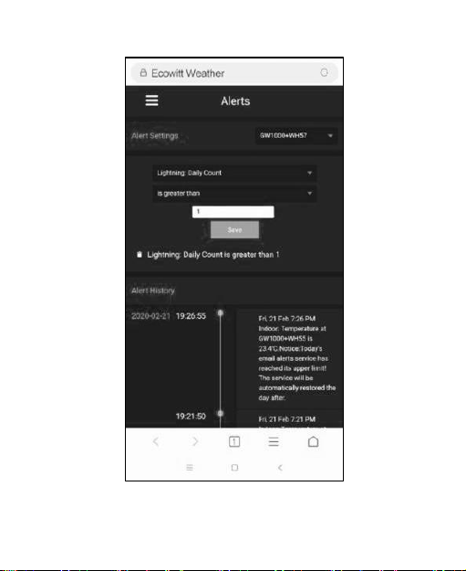
7. Set Email Alerts
Once your device is added successfully on the
Ecowitt Weather server, you may set alerts for
the lightning distance and daily count on the
website to get email notifications.
20
Table of contents
Other ECOWITT Accessories manuals


Popular Accessories manuals by other brands


Datalogic
Datalogic S100W instruction manual

Brinsea
Brinsea Ova-Easy Advance Series II User instructions

Eterna
Eterna BH24B Safety and installation instructions

Panasonic
Panasonic WJ-HDE500 instructions

Owon
Owon ZigBee WSP403 quick start guide

TP
TP Challenger TP541 Instructions for assembly maintenance and use