ECOWITT GW1003 User manual

1
Wi-Fi Weather Station
With Ultrasonic Anemometer Sensor Package and Rain Gauge Sensor
Operation Manual
Model: GW1003
Thank you for purchasing this GW1003 Wi-Fi Weather Station, a complete
weather station with ultrasonic anemometer and independent self-emptying
rain gauge.
This manual will guide you, step-by-step, through setting up your weather
station and base unit, and understanding the operation of your weather
station.
Note: The mounting pole for anemometer sensor package is not included.

2
1Table of Contents
1 TABLE OF CONTENTS ..................................................................................... 2
2 UNPACKING........................................................................................................ 4
3 OVERVIEW.......................................................................................................... 6
3.1 WI-FI GATEWAY .............................................................................................. 6
3.2 ULTRASONIC ANEMOMETER WITH 6-IN-1 SENSORS........................................... 6
3.3 RAIN SENSOR ................................................................................................... 7
3.4 FEATURES......................................................................................................... 7
4 SET UP GUIDE .................................................................................................... 9
4.1 SITE SURVEY.................................................................................................... 9
4.2 ULTRASONIC ANEMOMETER PACKAGE ASSEMBLY ......................................... 10
4.2.1 Install batteries in sensor package......................................................... 12
4.2.2 Mount ultrasonic anemometer assembly................................................ 13
4.2.3 Reset Button and Transmitter LED ........................................................ 17
4.3 RAIN GAUGE SENSOR SET UP AND INSTALLATION......................................... 17
4.3.1 Install rain gauge filter .......................................................................... 18
4.3.2 Install rain collector top......................................................................... 18
4.3.3 Install Batteries in rain gauge sensor .................................................... 19
4.3.4 Mounting................................................................................................ 20
4.4 BEST PRACTICES FOR WIRELESS COMMUNICATION ....................................... 22
4.5 WI-FI GATEWAY INTRODUCTION ................................................................... 24
4.5.1 LED Indicators....................................................................................... 24
4.5.2 Button functions ..................................................................................... 25
5 PUBLISH TO INTERNET WEATHER SERVICES...................................... 26
5.1 GATEWAY WI-FI CONFIGURATION................................................................. 26
5.2 ADDING WEATHER SERVICES.......................................................................... 29
5.3 ECOWITT WEATHER ....................................................................................... 31
5.3.1 Viewing data on ecowitt.net ................................................................... 32
5.4 WEATHER UNDERGROUND............................................................................. 35
5.4.1 WU Dashboard vs Live Data.................................................................. 36

3
5.5 EDITING RAIN TOTALS.................................................................................... 36
5.5.1 Calibration of anemometer sensor package........................................... 37
5.5.2 Calibration of barometric pressure settings........................................... 37
5.6 REGISTERING WITH AND USING WUNDERGROUND.COM.................................. 41
5.7 DEVICE SETTINGS........................................................................................... 43
5.8 SENSOR ID...................................................................................................... 43
5.9 VIEWING DATA ON WUNDERGROUND.COM..................................................... 43
6 MAINTENANCE................................................................................................ 46
7 TROUBLESHOOTING GUIDE ....................................................................... 48
8 SPECIFICATIONS............................................................................................. 51
9 WARRANTY INFORMATION........................................................................ 53

4
2Unpacking
Open your weather station box and inspect that the contents are intact
(nothing broken) and complete (nothing missing). Inside you should find the
following:
QTY
Item Description
1
USB Wi-Fi Gateway
1
Cable clip
1
Solar powered ultrasonic anemometer with Light and UV, air
temperature/humidity sensor integrated( optional heater for climate with
snow/ice conditions available)
1
Rain gauge
2
U-Bolts set for mounting on a pole (2pcs/set)
2
Threaded nuts for U-Bolts set (M5 size) (4pcs/set)
1
Metal mounting plate set to be used with U-Bolts (1pcs/set)
1
Mounting arm for ultrasonic anemometer
1
Mounting bracelet for ultrasonic anemometer
1
Stainless steel tube (for mounting the rain gauge sensor)
1
Mini wrench for M5 bolts
1
Stainless steel filter for rain gauge collector
1
User manual (this manual)
Table 1: Package content
If any component is missing from the package, or broken, please contact our
Customer Service department to resolve the issue.
Note: The gateway must be plugged into a USB (2.0 or later) port for its power
supply. You may want to use a USB extension cable (USB type A - Male
straight to female straight; not included) to allow for easier placement.
Note: Batteries for the ultrasonic anemometer and the rain gauge sensor are not
included. You will need 2 AA size Lithium battery for the ultrasonic
anemometer, which is primarily for startup and backup purpose. After

5
setup and during normal operation, the unit is getting its power from solar
cell. One AA size battery, alkaline or Lithium (recommended for colder
climates) is required for the rain gauge. Two AA size alkaline batteries are
required for the indoor sensor.
Note: There are two sets of U-bolts in the box, one is for the ultrasonic
anemometer sensor and the other one is for the rain gauge sensor. There’s a
short stainless-steel tube included for the rain gauge sensor installation.
Note: The rain gauge can also be mounted to a surface using two screws, so the
included stainless-steel tube is not always necessary!
6
3Overview
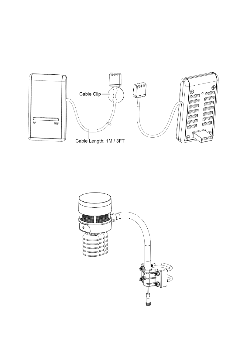
3.1 Wi-Fi Gateway
Figure 1: Wi-Fi Gateway
3.2 Ultrasonic anemometer with 6-in-1 sensors
Figure 2: Solar powered ultrasonic anemometer with integrated solar & uv,
thermo-hygrometer sensor
7
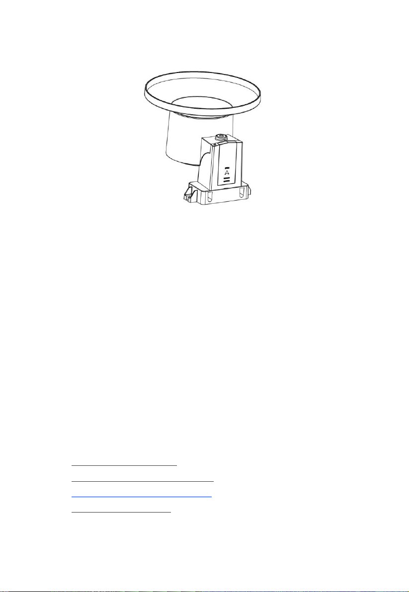
3.3 Rain Sensor
Figure 3: Self emptying rain gauge
3.4 Features
USB Wi-Fi Gateway
Built-in temperature, humidity and atmospheric pressure sensors (cabled
probe attached).
Collects sensor data from various supported wireless sensors.
Additional/optional sensors:
Up to 8 WH31 multi-channel temperature and humidity sensors
Up to 8 WH51 soil moisture sensors
Up to 4 WH41 PM2.5 air quality sensors
Future sensors (to be developed), such as: water leakage, lightning
Calculates dewpoint for outdoor sensor (cloud upload supported)
Pushes sensor data to cloud weather services:
https://www.ecowitt.net
https://www.wunderground.com
https://www.weathercloud.com/
https://www.wow.com
Custom own server data hosting possible when server data exchange
is compatible with either Wunderground or Ecowitt protocol.

8
Mobile application (WS View)
View collected live data( in same WLAN network).
Manage sensor calibration setup.
Manage sensor via sensor ID.
Data storage service on Ecowitt server: https://ecowitt.net
Stores data for past year days at 5-minute intervals
Stores data for past 2 years at 30-minute intervals
Outdoor Sensors
Outdoor temperature and humidity.
Wind speed, gust speed, and wind direction.
Rainfall rate and totals for day, week, month, and year.
Solar light intensity and UV index
Note: The optional WH31, WH41 and WH51 can be purchased separately. If
more info needed, please visit our website: http://www.ecowitt.com. Make
sure to select the model of the units with the same RF frequency as your
gateway (the frequency is different for various countries because of
regulations).
Note: There’s a built-in heat plate in the 6-in-1 sensor package body, if the lowest
temperature at your place is below -3°C, or 26.6°F , and the weather is
mostly snowy or rainy, then you may need to activate the heater by
supplying a 5V/1A power to the sensor heating element for melting
accumulated snow or ice, which can influence wind measurement accuracy
cord information.

9
4Set up Guide
Before you start, you will need a Philips screwdriver (size PH0, not
provided) and find the wrench (size M5) included in package.
Note: We suggest you assemble all components of the weather station, including
(optional) base unit in one location so you can easily test functionality.
After testing, place the outdoor sensors in the desired location. Note,
however, that movement during assembly, and movement after assembly
can cause the rain sensor to “falsely” register rain. It is possible to reset the
rain total to 0 via WS View app.
Attention:
Follow the suggested order for battery installation (outdoor sensor(s)
first, indoor sensor(s) second, optional base unit last).
Ensure batteries are installed with correct polarity (+/-).
Only use new batteries for all battery-operated sensors.
If rechargeable batteries to be used, please make sure they are pre-
charged fully and it is with Ni-Mh low-self-discharge type.
If outdoor temperature may go below 32 F or 0 C for prolonged periods,
Lithium based batteries are suggested over alkaline type batteries for
any outdoor sensor.
When outdoor temperature is above 10.0C ( 50.0F), it is forbidden to
feed power to the heating thermostat which can lead to permanent
damage due to excessive heat built up inside and cause unpredictable
damage to the system itself or data accuracy.
4.1 Site Survey
Location of various sensors is paramount to good data collection.
Abbreviated instructions follow, but for a detailed reference, see:
https://www.weather.gov/media/epz/mesonet/CWOP-Siting.pdf.

10
Perform a site survey before installing the weather station. Consider the
following:
Anemometer
Ideally mounted at least 32 feet, or 10 meters above ground level.
Try to make the anemometer the highest object around. 7 feet, or 2.75
meters) or more above the surrounding obstructions is best.
Rain Gauge
Ideally mounted at a height of 4 to 6 feet, or 1.5 to 2 meters above the
ground.
Ideally located at a horizontal distance of 4 times the height, above the
rain gauge, of the nearest obstruction.
Ensure the rain gauge is mounted level to the ground, away from any
horizontal surface that can introduce rain-splashing or surrounding snow
buildup.
4.2 Ultrasonic Anemometer package assembly
See Figure 4 to locate and understand all the parts of the ultrasonic
anemometer package with UV & light, thermo-hygrometer sensors, once
fully assembled.

11
Figure 4: Sensor package assembly components
1. Surface tension conditioner layer
( patented globally for solving water
drops influence on wind measurement)
7. Mounting arm
2. Battery compartment
8. Mounting bracelet and U-bolt set
3. Temperature & humidity sensor
9. Power cord for built-in heater
4. Light & UV sensor, LED indicator
10. USB port(for firmware upgrade
only)
5. Solar Panel
11. Calibration button
6. NORTH alignment indicator
12. Reset button
Table 2: Sensor package assembly component list

12
4.2.1 Install batteries in sensor package
Open the battery compartment with a screwdriver and insert 2 AA batteries
in the battery compartment, and press “Reset” button, the LED indicator on
the back of the sensor package (item 4) will turn on for 3 seconds and then
flash once every 4.75 seconds indicating sensor data transmission. If you did
not pay attention, you may have missed the initial indication. You can
always press the reset button to start over. Make sure you see the flash once
every 4.75 seconds.
If sensor has been put outside for some time, and solar panel has charged up
the internal accumulator fully or partially, if you install the 2 AA backup
battery, the system won’t be effected with its working condition. So you can
always make a system reset by press the “Reset” button.
Figure 5: Battery installation diagram
Note: Please make sure the battery is inserted correctly for its polarity as the
system needs its initial power from this backup battery to start up the
system before solar panel charges up the accumulator and take over power
supply afterwards. And when in high altitude area in winter when
sunshine time is short, system needs to be powered from this backup
battery, so we recommend Lithium batteries for cold weather climates.
Please avoid alkaline batteries, especially when internal heater is to be
13
activated during cold and wet weather conditions. When heater activated,
heat will be trapped inside to warm up the sonic reflection surface, and
alkaline batteries are extremely susceptible to leakage when temperature is
over certain limits. So Alkaline batteries are forbidden to be used with
this anemometer.
4.2.2 Mount ultrasonic anemometer assembly
4.2.2.1 Before you mount
Before installing your outdoor sensor in the permanent location, we
recommend operating the device for one week in a temporary location with
easy access. This will allow you to check out all of the functions, insure
proper operation and familiarize you with the weather station and calibration
procedures.
4.2.2.2 Mounting
You can attach a pole(not included) to a permanent structure and then
attach the sensor package to it (see Figure 6-10).
The U-Bolts will accommodate a pole diameter of 1.25-2 inches (pole
not included).
1.Install the base on a pole (1.25inch~2inch) as Figure 6.
Figure 6: Sensor package mounting diagram 5-1

14
2.Pass the connector cord through the arm tube as Figure 7:
Figure 7: Sensor package mounting diagram 5-2
3.Attaching the arm tube to the Ultrasonic Sensor as Figure 8.
Figure 8: Sensor package mounting diagram 5-3
4.Insert the arm tube into the base as Figure 9. Be sure to line up the
small hole in the arm with the holes in the base. Insert the machine
screw through the holes in the base and arm. ( if you don’t need to
power up the heater, you should keep the power cord terminal inside
the mounting arm and this can make the installation looks neat and
tidy. You may take it out when needed.)

15
Figure 9: Sensor package mounting diagram 5-4
Make sure the mounting pole is vertical, or very close to it. Use a level as
needed.
5. If optional extension cord is added, connect the cord to the connector
and insert the USB port into the AC adaptor as Figure 10 show:

16
Figure 10: Sensor package mounting diagram 5-5
Finally, place the sensor package on top of the prepared mounting pipe. The
U-Bolts should be loose enough to allow this but loosen the nuts as
necessary. Once placed, hand tighten all four nuts, taking care to do so
evenly. Do not use a wrench yet!
Now you will need to align the whole package in the proper direction by
rotating it on top of the mounting pipe as needed. Locate the arrow labeled
“NORTH” that you will find on top of the connector tube of the sensor
package (item 6). You must rotate the whole sensor package until this arrow
points due north. To achieve proper alignment, it is helpful to use a compass
(many cell phones have a compass application). Once rotated in the correct
orientation, lightly tighten the bolts a little more (use a wrench) to prevent
further rotation.
Note: In Southern hemisphere, it is not necessary to change the orientation to
SOUTH as its solar panel is a rounded type and it is orientation free for its
charging capability.
17
Make sure the mounting tube for the sensor package is installed vertically
(use a level at 90-degree offsets around the tube). Adjust the mounting pipe
as necessary. Next also make sure the mounting of the anemometer body on
the pipe is level. If it is not, wind direction and speed readings may not
operate correctly or accurately. Adjust the mounting assembly as necessary.
Make sure you check, and correct if necessary, the north orientation again,
as the final installation step, and now tighten the bolts with a wrench. Do not
over tighten, but make sure strong wind and/or rain cannot move the sensor
package.
4.2.3 Reset Button and Transmitter LED
In the event the sensor package is not transmitting, reset the sensor.
Using a bent-open paperclip, press and hold the RESET BUTTON (item 12)
to affect a reset: the LED turns on while the RESET button is depressed, and
you can now let go. The LED should then resume as normal, flashing
approximately once every 4.75 seconds.
4.3 Rain Gauge Sensor Set Up and Installation
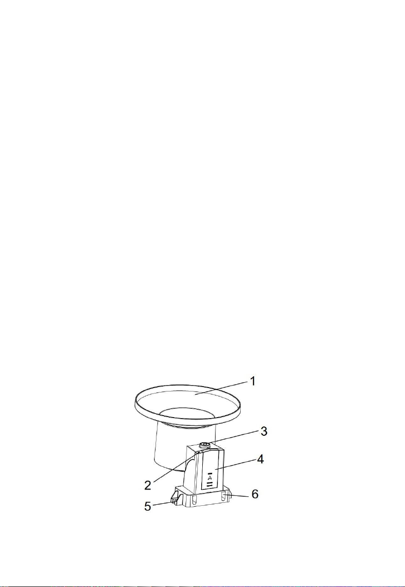
See Figure 11 to locate and understand all the parts of the rain gauge sensor
once fully assembled.
Figure 11: Sensor assembly components

18
1 Rain collector funnel
4 Battery compartmentdoor
2 LED Indicator
5 Surface installation screw hole
3 Bubble level
6 U-bolt installation hole
Table 3: Sensor assembly detailed items
4.3.1 Install rain gauge filter
There’s a stainless steel filter included in the package. It’s aimed to stop
leaves or bird's dropping to avoid the obstruction of the cone hole. The
installation is simple: press the filter until the hook is inside the outlet hole
and self locked. The spring tension will keep the filter sit tight on the funnel.
Figure 12: Rain gauge filter in/un-installation diagram
4.3.2 Install rain collector top
Align the rain collector top with the rain bucket, pay attention to the lock
groove position as shown on the left side in Figure 13. Next, lock the top
clockwise to the lock groove position, as shown on the right side of the
Hook the filter hook on the edge to install.
Take out the filter hook from the edge to uninstall.

19
figure, until it comes to a stop and the top cannot be removed from the
bucket. Failure to do this may cause the collector top to blow away in strong
winds!
Figure 13: Rain collector top installation diagram
4.3.3 Install Batteries in rain gauge sensor
Remove the battery door on the back of the sensor by sliding it in the
direction of the arrow. Insert one AA battery as described and put
compartment door back and slide it in the opposite direction to lock.
Figure 14: Rain gauge sensor battery installation diagram
The LED indicator on the top of the battery door (item 2) will turn on for 4
seconds and then flash once every 49 seconds indicating sensor data
transmission. If you did not pay attention, you may have missed the initial
indication. You can always remove the batteries and start over, but if you
see the flash once every 49 seconds, everything should be OK.

20
Note: If no LED light up or is lighted permanently, make sure the battery is
inserted the correct way or a proper reset is happened. Do not install the
batteries backwards. You can permanently damage the outdoor sensor.
We recommend lithium batteries for cold weather climates, but alkaline
batteries are sufficient for most climates.
4.3.4 Mounting
4.3.4.1 Before you mount
Before proceeding with the outdoor mounting detailed in this section, you
may want to skip to setup instructions in section 4.5 and onwards first, while
you keep the assembled rain gauge sensor nearby (although preferably not
closer than 5 ft. from the gateway). This will make any troubleshooting and
adjustments easier and avoids any distance or interference related issues
from the setup.
After setup is complete and everything is working, return here for outdoor
mounting. If issues show up after outdoor mounting they are almost
certainly related to distance, obstacles etc.
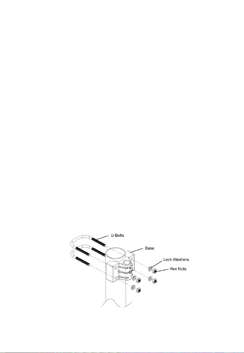
4.3.4.2 Mounting with U-bolts
The mounting assembly includes two U-Bolts and a bracket that tightens
around a 1-2" diameter pole using the four U-Bolt and nuts. The package
includes a D32/H200 (diameter 32mm = 1.26”, length 200mm = 7.87”)
stainless steel tube for this purpose.
Table of contents
Other ECOWITT Weather Station manuals

ECOWITT
ECOWITT WH0290 User manual

ECOWITT
ECOWITT WN1900 User manual

ECOWITT
ECOWITT WN1980 User manual

ECOWITT
ECOWITT WS69 User manual

ECOWITT
ECOWITT WS3900 User manual

ECOWITT
ECOWITT GW1100 User manual

ECOWITT
ECOWITT GW1001 User manual

ECOWITT
ECOWITT HP2553 User manual

ECOWITT
ECOWITT WH2910 User manual

ECOWITT
ECOWITT WS3800 User manual

ECOWITT
ECOWITT HP2552 User manual

ECOWITT
ECOWITT HP2553 User manual

ECOWITT
ECOWITT WN67 User manual

ECOWITT
ECOWITT GW1000 User manual

ECOWITT
ECOWITT WN190 User manual

ECOWITT
ECOWITT WS2910 User manual

ECOWITT
ECOWITT WH31 User manual

ECOWITT
ECOWITT WN1980 User manual

ECOWITT
ECOWITT HP2551 User manual

ECOWITT
ECOWITT WH5360B User manual


