edc DT 500 User manual
DT 500 Rev1.0 May20 Page 1 of 48
Instruction manual
Flow sensor DT 500
with Display, 4 ... 20 mA and Pulse output (galv. isolated)
Stationary and mobile
flow and consumption measurement for compressed air and gases
EN - English

Foreword
DT 500 Rev1.0 May20 Page 2 of 48
I. Foreword
Dear customer,
thank you very much for deciding in favour of the DT 500. Please read this
installation and operation manual carefully before mounting and initiating the device
and follow our advice. A riskless operation and a correct functioning of the
DT 500 are only guaranteed in case of careful observation of the described
instructions and notes.

Table of Content
DT 500 Rev1.0 May20 Page 3 of 48
II. Table of content
I. Foreword ....................................................................................................................... 2
1Intended use.................................................................................................................. 5
2Safety instructions........................................................................................................ 5
3Instruments description ............................................................................................... 7
4Technical data............................................................................................................... 8
5Installation..................................................................................................................... 9
5.1 Pipe/tube requirements ......................................................................................................... 9
5.2 Inlet / outlet runs .................................................................................................................... 9
5.3 Installation DT 500 ............................................................................................................... 10
5.3.1 ½“ welded nipple with ball valve ½“ ................................................................................. 10
5.3.2 Spot drilling collar with ball valve..................................................................................... 10
5.4 Installation of the Sensor.................................................................................................... 11
5.4.1 Mounting DT 500 onto the ball valve............................................................................... 11
5.5 Display Head Position ......................................................................................................... 12
6Measuring ranges........................................................................................................13
6.1 Maximum Flow Ranges „Low Speed“................................................................................ 14
6.2 Maximum Flow Ranges „Standard“ ................................................................................... 16
6.3 Maximum Flow ranges „Max speed“ ................................................................................. 18
6.4 Maximum Flow ranges „High speed“ ................................................................................ 20
7Dimension ....................................................................................................................22
8Electrical wiring ...........................................................................................................23
8.1 Modbus RTU, 4..20mA, Pulse or MBus.............................................................................. 23
8.2 Ethernet (optional PoE) ...................................................................................................... 24

Table of Content
DT 500 Rev1.0 May20 Page 4 of 48
9Operation......................................................................................................................25
9.1 Initialization .......................................................................................................................... 26
9.2 Main menu ............................................................................................................................ 26
9.3 Settings................................................................................................................................. 27
9.3.1 Sensor Setup................................................................................................................... 28
9.3.1.1 Input / change tube diameter.................................................................................... 28
9.3.1.2 Input / change consumption counter........................................................................ 29
9.3.1.3 Definition of the units for flow, velocity, temperature and pressure ......................... 29
9.3.1.4 Definition of the reference conditions....................................................................... 30
9.3.1.5 Setting of Zeropoint and Low-flow cut off................................................................. 32
9.3.2 Modbus Settings.............................................................................................................. 33
9.3.2.1 Modbus RTU Setup.................................................................................................. 33
9.3.2.2 Modbus TCP (Optional)............................................................................................ 34
9.3.2.2.1 Network Setup DHCP........................................................................................... 34
9.3.2.2.2 Network Settings static IP..................................................................................... 35
9.3.2.2.3 Modbus TCP Settings........................................................................................... 36
9.3.2.3 Modbus Settings Register (2001…2005) ................................................................ 37
9.3.2.4 Values Register (1001 …1500) ................................................................................ 37
9.3.3 Pulse /Alarm..................................................................................................................... 39
9.3.3.1 Pulse output.............................................................................................................. 39
9.3.4 User Setup....................................................................................................................... 40
9.3.4.1 Password.................................................................................................................. 40
9.3.4.2 Language.................................................................................................................. 40
9.3.4.3 Display / Touch......................................................................................................... 41
9.3.5 Advanced......................................................................................................................... 41
9.3.6 4 -20mA ........................................................................................................................... 42
9.3.7 DT 500 Info...................................................................................................................... 44
9.4 MBus...................................................................................................................................... 45
9.4.1 Default Settings communication...................................................................................... 45
9.4.2 Default values transmitted ............................................................................................... 45
10 Status / Error messages...........................................................................................46
10.1 Status messages.................................................................................................................. 46
10.2 Error messages.................................................................................................................... 47
11 Maintenance..............................................................................................................48
12 Cleaning of the sensor head....................................................................................48
13 Re-Calibration...........................................................................................................48
14 Spare parts and repair..............................................................................................48
15 Calibration.................................................................................................................48
16 Warranty....................................................................................................................48

Safety Instruction
DT 500 Rev1.0 May20 Page 5 of 48
1 Intended use
The DT 500consumption sensor is used for continuous flow measurements.
The DT 500 consumption sensor is designed and constructed exclusively for the intended purpose
described here and may only be used accordingly.
The user must check whether the instrument is suitable for the selected application. It must be
ensured that the medium is compatible with the wetted parts. The technical data listed in the data
sheet are binding.
Improper handling or operation outside the technical specifications is not permitted. Claims of any kind
based on improper use are excluded.
2 Safety instructions
•Please check whether this manual also corresponds to the device type.
•This manual must be read before installation, commissioning and maintenance.
•Please observe all instructions given in this operating manual. It contains basic information
that must be observed during installation, operation and maintenance.
•In addition to these operating instructions, local or national regulations must be observed
where applicable.
•Make sure that the DT 500 is only operated within the permissible limits specified on the
nameplate. Otherwise there is a danger to people and material and malfunctions and
operating faults may occur
•Improper handling can lead to considerable personal injury and damage to property.
All activities described in this operating manual may only be carried out by qualified personnel
with the qualifications described below
•The safety ring attached to the sensor head must always be undamaged and correctly fitted..
•The screw-in device must be screwed in pressure-tight.
•The clamping sleeve must be tightened with a tightening torque of 20-30 Nm.
•In the event of non-observance or non-compliance, the manufacturer cannot be held liable for
any resulting damage. Interventions of any kind on the device, if they do not correspond to the
intended and described procedures, lead to the warranty being voided and to the exclusion of
liability.
•The device is intended exclusively for the described purpose.
•We do not assume any warranty with regard to the suitability for any particular purpose and no
liability for errors contained in these operating instructions. Nor for consequential damages in
connection with the delivery, performance or use of the device.
•Do not exceed the pressure range of 50 bar.
•Over 10 bar we recommend using the high-pressure protection for a safe installation.
Burnable gases
If this consumption sensor is used for measurement of burnable gases (e.g. natural gas) we explicitly
point out that the sensor has no DVGW (= German Technical Association for Gas and Water)
admission, however, it can be used for natural gas.
A DVGW admission is not mandatory.
The consumption sensor DT 500 corresponds with the latest state of technology and can
generally be used for burnable and non-burnable gases.
For the use in e.g. natural gas, the sensor will be calibrated in natural gas. The calibration protocol
(inspection certificate) is included in the scope of delivery.
The area outside the pipe (environment of the sensor) is not allowed to be an explosive area (Ex-area)
!

Safety Instruction
DT 500 Rev1.0 May20 Page 6 of 48
Please read carefully before starting the device!
The consumption sensor DT 500 measures the flow velocity (calorimetric principle) in the
center of the pipe. Please observe mounting instruction and inlet section = 15 x inner
diameter and outlet section = 5 x inner diameter.
The final values of the measuring ranges are as follows:
DT 500 standard version 92.7 m/s, please take the flow rates from the tables on pages 14-15
DT 500 max. version 185 m/s, please take the flow rates from the tables on pages 16-17
DT 500 high speed version 224 m/s, please take the flow rates from the tables on pages 18-19
1. DT 500 with Display with 4… 20 mA analogue- and pulse output
Please enter inner diameter of the pipe!
Values indicated in the display:
Actual value in m³/h, m³/min etc.
Counter in m³, l, cf
as well as pulse output, 1 pulse per m³, l, cf
are calculated according to the set diameter. Please take the analogue value for flow rate
4. 20 mA from the tables on pages 14 to 19
4 mA always corresponds with the starting value 0 m³/h, 0 m³/min. The final value 20 mA can be taken
from the tables on pages 14 to 19.
Example DT 500 Standard:
1" with inner diameter 25.0 mm, 4 mA = 0 m³/h and 20 mA = 122.2 m³/h
2" with inner diameter 53.1 mm, 4 mA = 0 m³/h und 20 mA = 600.0 m³/h
2. DT 500 without Display with 4… 20 mA analogue- and pulse output
No adjustments are necessary at the consumption sensor.
The respective final values for the flow rate can be taken from the tables on the pages 14 to 19.
Analogue start value 4 mA is always set as scaling value 0 m³/h, 0 m³/min etc.
Analogue end value 20 mA is the final value, see tables pages 14 -19.
Example DT 500 Standard:
1" with inner diameter 25.0 mm, 4 mA = 0 m³/h and 20 mA = 122.2 m³/h
2" with inner diameter 53.1 mm, 4 mA = 0 m³/h und 20 mA = 600.0 m³/h

Instruments description
DT 500 Rev1.0 May20 Page 7 of 48
3Instruments description
The DT 500 is a compact consumption counter for compressed air and gases.
Special features:
- Optimum accuracy due to compact design
- Integrated in- and outlet section
- Less flow due to measuring section
- Intgrated Display, Units free selectable. m³/h, m³/min, l/min, l/s, kg/h, kg/min, kg/s,
cfm
- Modbus RTU (RS485) Interface
- Analogoutput 4..20mA
- Pulse output galv. isolated.
-
PC Service Software
- Analogaoutput 4...20 mA scaleable
- Selection of gas type (Air, Nitrogen, Argon, Nitrous oxide, CO2, Oxygen, Natural gas)
- Read out Service data
- Sensor diagnoses

Technical data
DT 500 Rev1.0 May20 Page 8 of 48
4Technical data
Measurement: Flow, Consumption and Velocity
Reference: Standard settings ex works:
DIN 1945, ISO 1217 at 20°C and 1000 mbar
other standards can be adjusted by Display keys (optional)
or means of the PC Service Software.
Selectable Units: m³/h (Standard settings ex- factory)
m³/min, l/min, l/s, ft/min, cfm, m/s, kg/h, kg/min, kg/s, °C, °F
Measuring principle: calorimetric measurement
Sensor: Pt45, Pt1000
Measuring medium: Air, gases
Operating temperature: -20 ... 70°C housing
-30 ... 100°C probe tube
Relative humidity for
measuring medium: < 95 % r.H (no condensation on the sensor element allowed)
Operating pressure: up to 50 bar
Power supply: 10 to 36 VDC
Optional: PoE according to IEEE 802.3af, PD Class 2 (max.
6.5W), supply voltage from 36V to 57V DC
Power consumption: max. 5W
Digital output: RS 485 (Modbus RTU)
Analog output: 4...20 mA (see tables page 13 -18),
max. burden < 500 Ohm
Pulse output: pulse output potential free (dry contact)
passive: max. 48Vdc, 150mA
1 pulse pro m³ resp. pro l,
Valency adjustable with the display keys
Accuracy: ± 1,5 % m.v.*, ± 0,3 % f.s.*
Display: optional TFT 1.8“ Resolution 220 x 176
Mounting thread: G ½“, optional ½” NPT
Material: Stainless steel 1.4301 / 1.4404
Protection class IP65
‘* m.v. = measured values
f.s. = full scale
Installation
DT 500 Rev1.0 May20 Page 9 of 48
5 Installation
5.1 Pipe/tube requirements
•Correctly sized gaskets
•Correct aligned flanges and gaskets
•Diameter mismatch at the pipe junctions should be avoided but must be less than 1mm. For
further information see ISO 14511
•Ensure clean pipes after installation
•.
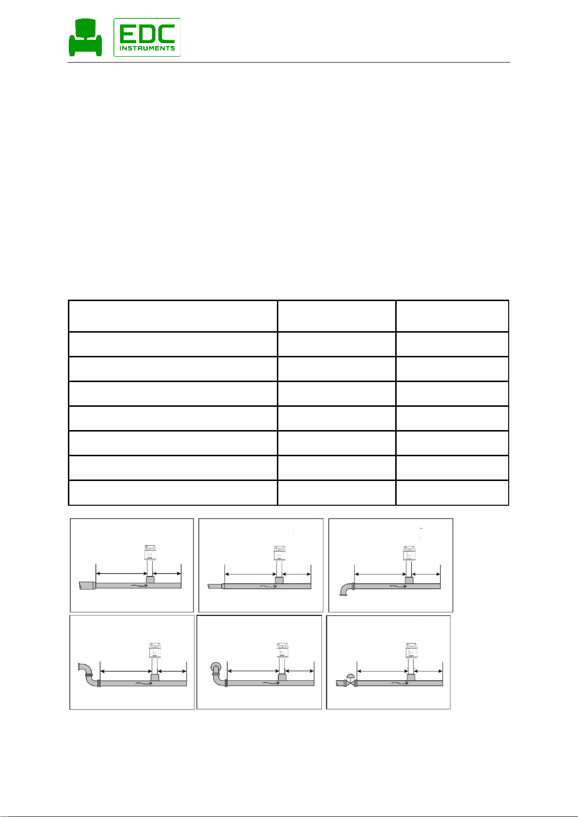
5.2 Inlet / outlet runs
In order to maintain the accuracy stipulated in the data sheets, the sensor must be inserted in the
centre of a straight pipe section with an undisturbed flow progression.
An undisturbed flow progression is achieved if the sections in front of the sensor (inlet) and behind the
sensor (outlet) are sufficiently long, straight and without any obstructions such as edges, seams,
curves etc.
Therefore, it is necessary to ensure the recommended inlet and outlet runs.
Table Inlet / Outlet runs
Flow obstruction before the measurement
section
Min length
Inlet run (L1)
Min length
Outlet run (L2)
Slight curve
(elbow < 90°)
12 x D
5 x D
Reduction
(Pipe narrows to the measurement section)
15 x D
5 x D
Expansion
(Pipe expands to the measurement section)
15 x D
5 x D
90° elbow or T-piece
15 x D
5 x D
2x elbow á 90°
in einer Ebene
20 x D
5 x D
2x elbow á 90°
3-dimensional
35 x D
5 x D
Control valve
45 x D
5 x D
15 x D 5 x D
15 x D 5 x D15 x D
15 x D 5 x D
20 x D 5 x D
35 x D 5 x D
5 x D45 x D
The values represent the min. lengths. In case the min. inlet / outlet runs could not be ensured, it must
be expected to get increased or significant deviations of the measurement values.

Installation
DT 500 Rev1.0 May20 Page 10 of 48
5.3 Installation DT 500
The installation of the sensor is done via a ball valve ½ ".
If no valid measuring point with a ball valve ½ " is available there are following ways to set up a
measuring point.
5.3.1 ½“ welded nipple with ball valve ½“
5.3.2 Spot drilling collar with ball valve
In case the system could not be shut down, means to be set depressurized, there could be used the
spot drilling collar and drilling jig to drill through the ball valve.
Important:
Ensure that the system is in shut down, ie. depressurized.
Note for installation with ball valve
Ball valve R 1/2“, DN 15
Passage ball valve: Minimum Ø15 mm
Installation
DT 500 Rev1.0 May20 Page 11 of 48
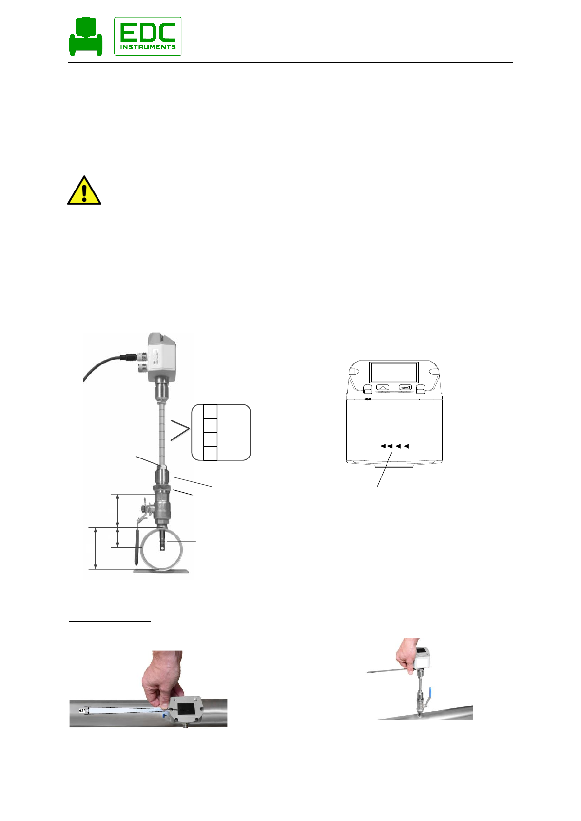
5.4 Installation of the Sensor
5.4.1 Mounting DT 500 onto the ball valve
•Assembly is carried out by inserting the connection thread with gasket. (G1/2“
thread, SW 32) into the ball valve with ½"internal thread.
The sensor has be tighten by hand as far as possible and then tighten with
stipulated torque of 25-30 Nm.
It must be ensured that the installation is pressure-tight.
•The sensor is then inserted to the required immersion depth (sensor tip in the
middle of pipe) and aligned according to the direction of the airflow.
A depth scale engraved on the probe tube, a flow alignment arrow and an
aligning device will be of help for you.
Once the sensor has been aligned the adapter sleeve must be tighten with
stipulated torque of 20-30Nm (SW 17).
Attention: Alignment of the sensor must not be modified when tightening the connection thread and
adapter sleeve. In this case, please check the immersion depth and alignment again and
correct it if necessary. The angular deviation should not be greater than 2° in relation to
ideal position as otherwise the measuring accuracy will decrease.
Calculation mounting depth: Alignment flow direction
Einbautiefe = X + Y
dA = Außendurchmesser
X = dA / 2
y
dA
x
160
170
180
Installationstiefe
Eingravierte Tiefenskala
für genauen Einbau
Sicherungsring
Spannhülse
Durchgangsverschraubung
Sensor alignment
A max. angle deviation of ±2° is permitted to ensure
correct measured values..
Indication flow direction

Installation
DT 500 Rev1.0 May20 Page 12 of 48
5.5 Display Head Position
The Position of the Display head is twistable by 180 e.g. in
case of reverse flow direction.
For this purpose the 6 fastening screws are to be released
and the display head rotated 180°.
Caution:
It must be ensured that the connection plugs are still plugged
and the gasket is installed correctly.
Fastening screws

Measuring ranges
DT 500 Rev1.0 May20 Page 13 of 48
6Measuring ranges
The consumption sensor DT500 is available in 4 different versions:
•Low Speed max. measuring range of 50 m/s
•Standard max. measuring range of 92,7 m/s
•Max–Version max. measuring range of 185.0 m/s
•High speed–Version max. measuring range of 224 m/s
The sensors are programmed to pipe inner diameter of 53,1 mm.
Measuring range Analogoue output Scaling
•Low Speed 0… 323,6 m³/h 4mA = 0 m³h, 20mA = 323,6 m³/h
•Standard 0 … 600 m³/h 4mA = 0 m³h, 20mA = 600 m³/h
•Max–Version 0 ... 1197,59 m³/h 4mA = 0 m³h, 20mA = 1197,59 m³/h
•Highspeed–Version 0 … 1450,06 m³/h 4mA = 0 m³h, 20mA = 1450,06 m³/h
In case of use in other inner pipe diameter the diameter, using the display version, the diameter has to be
set first.
The corresponding scale values for the respective version could be found in sections 5.1 to 5.3.
Example:
Pipe 1“, Inner diameter 25mm Measuring range Analogoue output Scaling
•Low Speed 0 … 65,9 m³/h 4mA = 0 m³h, 20mA = 65,9 m³/h
•Grundversion( Standard) 0 … 122,2 m³/h 4mA = 0 m³h, 20mA = 122,2 m³/h
•Max–Version 0 ... 243,88 m³/h 4mA = 0 m³h, 20mA = 243,88 m³/h
•Highspeed–Version 0 … 295,30 m³/h 4mA = 0 m³h, 20mA = 295,30 m³/h
For changing the inner pipe diameter and adjusting the 4…20mA scaling, please refer to chapter
“Operation”.
Please note:
The consumption sensor400 corresponds with the latest state of technology and can
generally be used for burnable and non-burnable gases.
If this consumption sensor is used for measurement of burnable gases (e.g. natural gas) we explicitly point
out that the sensor has no DVGW admission, however, it can be used for
burnable gases. A DVGW admission is not mandatory.
For the use in e.g. natural gas, the sensor will be calibrated in natural gas. The calibration protocol
(inspection certificate) is included in the scope of delivery.
The area outside the pipe (environment of the sensor) is not allowed to be an explosive area. (Ex area) .

Measuring ranges
DT 500 Rev1.0 May20 Page 14 of 48
6.1 Maximum Flow Ranges „Low Speed“
Inner diameter
of the pipe
Flow
(final value of measuring range in Nm³/h)
Max.
Inch
mm
Air2)
Air 3)
Ar3)
CO23)
N23)
O23)
N2O3)
Natural
gas3)
Methan
m/s
1/4"
6,0
2,5
2,3
4,0
2,5
2,3
2,4
2,5
1,5
50
10,0
8,1
7,4
12,6
8,0
7,4
7,7
7,9
4,8
50
15,0
21,0
19,3
32,8
20,8
19,3
20,0
20,6
12,4
50
1/2"
16,1
24,6
22,6
38,4
24,3
22,6
23,4
24,1
14,6
50
3/4"
21,7
48,1
44,2
75,1
47,6
44,2
45,8
47,1
28,4
50
1"
25,0
65,9
60,6
103,1
65,2
60,6
62,8
64,6
39,0
50
26,0
71,7
65,9
112,1
70,9
65,9
68,3
70,3
42,4
50
27,3
79,7
73,2
124,5
78,8
73,2
75,9
78,1
47,1
50
28,5
87,4
80,4
136,6
86,5
80,4
83,3
85,7
51,7
50
30,0
97,6
89,7
152,6
96,6
89,7
93,0
95,7
57,7
50
1 1/4"
32,8
118,0
108,5
184,5
116,8
108,5
112,5
115,8
69,8
50
36,0
143,6
132,1
224,6
142,1
132,1
136,9
140,9
85,0
50
36,3
146,2
134,5
228,6
144,7
134,5
139,4
143,4
86,5
50
1 1/2"
39,3
172,9
159,0
270,4
171,1
159,0
164,9
169,6
102,3
50
40,0
179,4
164,9
280,4
177,5
164,9
171,0
175,9
106,1
50
41,9
196,9
181,0
307,8
194,8
181,0
187,7
193,1
116,5
50
43,1
210,1
193,2
328,5
207,9
193,2
200,3
206,1
124,3
50
45,8
238,4
219,3
372,8
235,9
219,3
227,3
233,8
141,1
50
2"
50,0
286,3
263,3
447,6
283,3
263,3
272,9
280,8
169,4
50
51,2
300,6
276,4
469,9
297,4
276,4
286,5
294,8
177,9
50
53,1
323,7
297,6
506,1
320,3
297,6
308,6
317,5
191,5
50
54,5
341,4
313,9
533,8
337,8
313,9
325,5
334,8
202,0
50
57,5
403,1
370,7
630,3
399,0
370,7
384,4
395,4
238,6
50
60,0
417,3
383,8
652,5
413,0
383,8
397,9
409,3
247,0
50
64,2
479,5
441,0
749,8
474,6
441,0
457,2
470,3
283,8
50
2) Referred to DIN 1945 / ISO 1217 (20°C, 1000mbar) and compressed air.
3) Referred to DIN 1343: 0°C, 1013,25 mbar

Measuring ranges
DT 500 Rev1.0 May20 Page 15 of 48
Inner diameter
of the pipe
Flow
(final value of measuring range in Nm³/h)
Max.
Inch
mm
Air 2)
Air 3)
Ar3)
CO23)
N23)
O23)
N2O3)
Natural gas3)
Methan
m/s
2 1/2"
65,0
492,2
452,6
769,5
487,1
452,6
469,2
482,7
291,2
50
70,3
577,8
531,3
903,4
571,8
531,3
550,9
566,7
341,9
50
71,1
591,0
543,5
924,1
584,9
543,5
563,5
579,7
349,7
50
76,1
678,7
624,1
1061,2
671,7
624,1
647,1
665,7
401,6
50
3"
80,0
751,9
691,4
1175,5
744,1
691,4
716,8
737,4
444,9
50
82,5
799,6
735,3
1250,2
791,3
735,3
762,3
784,2
473,2
50
84,9
846,8
778,7
1324,0
838,0
778,7
807,3
830,5
501,1
50
90,0
952,7
876,1
1489,6
942,8
876,1
908,3
934,4
563,8
50
4"
100,0
1177,6
1082,9
1841,2
1165,4
1082,9
1122,7
1155,0
696,9
50
107,1
1352,4
1243,7
2114,5
1338,4
1243,7
1289,4
1326,4
800,3
50
110,0
1426,6
1311,9
2230,5
1411,8
1311,9
1360,2
1399,2
844,2
50
5"
125,0
1844,5
1696,1
2883,8
1825,3
1696,1
1758,5
1809,0
1091,5
50
133,7
2110,1
1940,5
3299,2
2088,2
1940,5
2011,8
2069,6
1248,7
50
6"
150,0
2659,2
2445,4
4157,6
2631,6
2445,4
2535,3
2608,1
1573,6
50
159,3
2999,2
2758,0
4689,2
2968,0
2758,0
2859,4
2941,6
1774,8
50
182,5
3941,1
3624,2
6161,8
3900,1
3624,2
3757,4
3865,4
2332,1
50
190,0
4271,6
3928,2
6678,7
4227,3
3928,2
4072,6
4189,6
2527,8
50
8"
200,0
4738,8
4357,7
7409,0
4689,5
4357,7
4517,9
4647,7
2804,2
50
206,5
5051,8
4645,6
7898,4
4999,3
4645,6
4816,4
4954,8
2989,4
50
10"
250,0
7413,2
6817,1
11590,4
7336,1
6817,1
7067,7
7270,8
4386,8
50
260,4
8052,4
7404,9
12589,8
7968,7
7404,9
7677,1
7897,7
4765,0
50
12"
300,0
10687,7
9828,3
16710,1
10576,6
9828,3
10189,6
10482,4
6324,5
50
309,7
11390,0
10474,2
17808,1
11271,6
10474,2
10859,2
11171,2
6740,1
50
339,6
13695,5
12594,2
21412,7
13553,1
12594,2
13057,2
13432,4
8104,4
50
400,0
19000,4
17472,6
29706,8
18802,9
17472,6
18114,9
18635,4
11243,6
50
500,0
29688,1
27300,9
46416,9
29379,5
27300,9
28304,5
29117,7
17568,1
50
600,0
42750,8
39313,3
66840,4
42306,5
39313,3
40758,4
41929,6
25298,0
50
700,0
58188,6
53509,8
90977,1
57583,9
53509,8
55476,8
57070,8
34433,4
50
800,0
76001,4
69890,3
118827,3
75211,6
69890,3
72459,4
74541,4
44974,3
50
900,0
96189,3
88454,9
150390,8
95189,7
88454,9
91706,5
94341,5
56920,6
50
1000,0
118752,2
109203,6
185667,6
117518,1
109203,6
113217,9
116471,0
70272,3
50
2) Referred to DIN 1945 / ISO 1217 (20°C, 1000mbar) and compressed air.
3) Referred to DIN 1343: 0°C, 1013,25 mbar

Measuring ranges
DT 500 Rev1.0 May20 Page 16 of 48
6.2 Maximum Flow Ranges „Standard“
Inner diameter
of the pipe
Flow
(final value of measuring range in Nm³/h)
Max.
Inch
mm
Air2)
Air 3)
Ar3)
CO23)
N23)
O23)
N2O3)
Natural gas3)
Methan
m/s
1/4"
6,0
4,7
4,3
7,4
4,7
4,3
4,5
4,6
2,8
92,7
10,0
14,9
13,7
23,4
14,8
13,7
14,2
14,7
8,8
92,7
15,0
38,9
35,8
60,9
38,5
35,8
37,1
38,2
23,0
92,7
1/2"
16,1
45,6
41,9
71,3
45,1
41,9
43,4
44,7
27,0
92,7
3/4"
21,7
89,1
81,9
139,3
88,2
81,9
84,9
87,4
52,7
92,7
1"
25,0
122,2
112,4
191,1
120,9
112,4
116,4
119,9
72,3
92,7
26,0
132,9
122,2
207,8
131,5
122,2
126,5
130,3
78,6
92,7
27,3
147,7
135,8
230,9
146,1
135,8
140,6
144,8
87,4
92,7
28,5
162,0
149,0
253,3
160,3
149,0
154,3
158,9
95,9
92,7
30,0
180,9
166,4
282,9
179,0
166,4
172,3
177,5
107,1
92,7
1 1/4"
32,8
218,8
201,2
342,1
216,5
201,2
208,4
214,6
129,5
92,7
36,0
266,3
244,9
416,4
263,5
244,9
253,6
261,2
157,6
92,7
36,3
271,1
249,3
423,9
268,3
249,3
258,2
265,9
160,4
92,7
1 1/2"
39,3
320,6
294,8
501,3
317,3
294,8
305,3
314,5
189,7
92,7
40,0
332,6
305,8
519,9
329,1
305,8
316,7
326,2
196,8
92,7
41,9
365,0
335,6
570,6
361,2
335,6
347,6
358,0
216,0
92,7
43,1
389,5
358,2
609,0
385,4
358,2
370,9
382,0
230,5
92,7
45,8
442,0
406,5
691,1
437,4
406,5
421,0
433,5
261,6
92,7
2"
50,0
530,8
488,1
829,8
525,2
488,1
505,5
520,6
314,1
92,7
51,2
557,2
512,4
871,2
551,4
512,4
530,7
546,5
329,7
92,7
53,1
600,1
551,8
938,2
593,8
551,8
571,5
588,6
355,1
92,7
54,5
632,9
582,0
989,5
626,3
582,0
602,7
620,8
374,5
92,7
57,5
747,4
687,3
1168,5
739,6
687,3
711,8
733,1
442,3
92,7
60,0
773,7
711,5
1209,7
765,6
711,5
736,8
758,9
457,9
92,7
64,2
889,1
817,6
1390,0
879,8
817,6
846,7
872,0
526,1
92,7
2) Referred to DIN 1945 / ISO 1217 (20°C, 1000mbar) and compressed air.
3) Referred to DIN 1343: 0°C, 1013,25 mbar

Measuring ranges
DT 500 Rev1.0 May20 Page 17 of 48
Inner diameter
of the pipe
Flow
(final value of measuring range in Nm³/h)
Max.
Inch
mm
Air 2)
Air 3)
Ar3)
CO23)
N23)
O23)
N2O3)
Natural gas3)
Methan
m/s
2 1/2"
65,0
912,5
839,1
1426,6
902,9
839,1
869,0
895,0
540,0
92,7
70,3
1071,2
985,1
1674,8
1060,0
985,1
1020,2
1050,7
633,9
92,7
71,1
1095,8
1007,7
1713,1
1084,3
1007,7
1043,5
1074,7
648,4
92,7
76,1
1258,3
1157,2
1967,3
1245,2
1157,2
1198,3
1234,2
744,6
92,7
3"
80,0
1394,0
1281,9
2179,4
1379,4
1281,9
1327,5
1367,2
824,9
92,7
82,5
1482,5
1363,3
2317,7
1466,9
1363,3
1411,8
1454,0
877,2
92,7
84,9
1570,0
1443,7
2454,5
1553,5
1443,7
1495,1
1539,8
929,0
92,7
90,0
1766,4
1624,3
2761,6
1747,9
1624,3
1682,1
1732,4
1045,3
92,7
4"
100,0
2183,3
2007,8
3413,5
2160,5
2007,8
2079,2
2141,4
1292,0
92,7
107,1
2507,4
2305,7
3920,1
2481,1
2305,7
2387,8
2459,2
1483,7
92,7
110,0
2645,0
2432,3
4135,3
2617,3
2432,3
2518,9
2594,2
1565,2
92,7
5"
125,0
3419,6
3144,7
5346,3
3383,8
3144,7
3256,6
3353,9
2023,6
92,7
133,7
3912,2
3597,6
6116,5
3871,3
3597,6
3725,7
3837,0
2315,1
92,7
6"
150,0
4930,2
4533,7
7708,0
4878,6
4533,7
4695,1
4835,4
2917,4
92,7
159,3
5560,5
5113,3
8693,4
5502,3
5113,3
5295,3
5453,6
3290,4
92,7
182,5
7306,7
6719,2
11423,6
7230,3
6719,2
6958,3
7166,4
4323,8
92,7
190,0
7919,6
7282,8
12381,8
7836,8
7282,8
7542,0
7767,5
4686,5
92,7
8"
200,0
8785,7
8079,2
13735,8
8693,8
8079,2
8366,8
8616,9
5199,0
92,7
206,5
9366,0
8612,9
14643,2
9268,0
8612,9
8919,4
9186,1
5542,4
92,7
10"
250,0
13744,0
12638,9
21487,8
13600,2
12638,9
13088,7
13480,0
8133,1
92,7
260,4
14929,1
13728,7
23340,6
14772,9
13728,7
14217,2
14642,3
8834,4
92,7
12"
300,0
19815,0
18221,7
30979,4
19607,7
18221,7
18870,1
19434,3
11725,6
92,7
309,7
21117,1
19419,1
33015,1
20896,1
19419,1
20110,1
20711,4
12496,1
92,7
339,6
25391,4
23349,7
39697,7
25125,7
23349,7
24180,6
24903,6
15025,5
92,7
400,0
35226,7
32394,1
55074,4
34858,0
32394,1
33546,9
34549,9
20845,6
92,7
500,0
55041,6
50615,8
86053,8
54465,7
50615,8
52417,0
53984,3
32571,2
92,7
600,0
79260,0
72886,8
123917,4
78430,6
72886,8
75480,5
77737,4
46902,5
92,7
700,0
107881,6
99207,0
168665,4
106752,8
99207,0
102737,4
105809,2
63839,5
92,7
800,0
140906,6
129576,5
220297,7
139432,2
129576,5
134187,6
138199,7
83382,2
92,7
900,0
178334,9
163995,2
278814,3
176468,9
163995,2
169831,2
174909,1
105530,6
92,7
1000,0
220166,6
202463,2
344215,1
217862,8
202463,2
209668,2
215937,1
130284,7
92,7
2) Referred to DIN 1945 / ISO 1217 (20°C, 1000mbar) and compressed air.
3) Referred to DIN 1343: 0°C, 1013,25 mbar

Measuring ranges
DT 500 Rev1.0 May20 Page 18 of 48
6.3 Maximum Flow ranges „Max speed“
Inner diameter
of the pipe
Flow
(final value of measuring range in Nm³/h)
Max.
Inch
mm
Air 2)
Air 3)
Ar3)
CO23)
N23)
O23)
N2O3)
Natural gas3)
Methan
m/s
1/4"
6,0
9,4
8,7
14,7
9,3
8,7
9,0
9,2
5,6
185,0
10,0
29,8
27,4
46,6
29,5
27,4
28,4
29,2
17,6
185,0
15,0
77,7
71,4
121,4
76,9
71,4
74,1
76,2
46,0
185,0
1/2"
16,1
91,0
83,7
142,2
90,0
83,7
86,7
89,2
53,8
185,0
3/4"
21,7
177,8
163,5
278,0
176,0
163,5
169,5
174,4
105,2
185,0
1"
25,0
243,9
224,3
381,3
241,3
224,3
232,5
239,2
144,3
185,0
26,0
265,2
243,9
414,6
262,4
243,9
252,8
260,1
156,9
185,0
27,3
294,7
271,0
460,8
291,7
271,0
281,0
289,1
174,4
185,0
28,5
323,3
297,3
505,5
320,0
297,3
308,3
317,1
191,3
185,0
30,0
361,1
332,0
564,5
357,3
332,0
344,3
354,1
213,7
185,0
1 1/4"
32,8
436,7
401,6
682,8
432,2
401,6
416,3
428,3
258,4
185,0
36,0
531,5
488,7
831,0
526,0
488,7
506,7
521,3
314,5
185,0
36,3
541,1
497,6
845,9
535,4
497,6
515,8
530,7
320,2
185,0
1 1/2"
39,3
639,8
588,4
1000,4
633,2
588,4
610,0
627,6
378,6
185,0
40,0
663,7
610,3
1037,7
656,8
610,3
632,7
650,9
392,7
185,0
41,9
728,4
669,8
1138,9
720,8
669,8
694,5
714,4
431,0
185,0
43,1
777,3
714,8
1215,4
769,3
714,8
741,1
762,4
460,0
185,0
45,8
882,2
811,2
1379,3
873,0
811,2
841,1
865,2
522,0
185,0
2"
50,0
1059,2
974,1
1656,1
1048,2
974,1
1009,9
1038,9
626,8
185,0
51,2
1112,1
1022,6
1738,7
1100,5
1022,6
1060,2
1090,7
658,1
185,0
53,1
1197,6
1101,3
1872,4
1185,1
1101,3
1141,8
1174,6
708,7
185,0
54,5
1263,1
1161,6
1974,9
1250,0
1161,6
1204,3
1238,9
747,5
185,0
57,5
1491,6
1371,7
2332,1
1476,1
1371,7
1422,1
1463,0
882,7
185,0
60,0
1544,1
1420,0
2414,2
1528,1
1420,0
1472,2
1514,5
913,7
185,0
64,2
1774,3
1631,7
2774,1
1755,9
1631,7
1691,6
1740,2
1050,0
185,0
2) Referred to DIN 1945 / ISO 1217 (20°C, 1000mbar) and compressed air.
3) Referred to DIN 1343: 0°C, 1013,25 mbar

Measuring ranges
DT 500 Rev1.0 May20 Page 19 of 48
Inner diameter
of the pipe
Flow
(final value of measuring range in Nm³/h)
Max.
Inch
mm
Air 2)
Air 3)
Ar3)
CO23)
N23)
O23)
N2O3)
Natural gas3)
Methan
m/s
2 1/2"
65,0
1821,0
1674,6
2847,2
1802,1
1674,6
1736,2
1786,1
1077,6
185,0
70,3
2137,9
1966,0
3342,5
2115,6
1966,0
2038,2
2096,8
1265,1
185,0
71,1
2186,8
2011,0
3419,0
2164,1
2011,0
2084,9
2144,8
1294,0
185,0
76,1
2511,2
2309,3
3926,3
2485,1
2309,3
2394,2
2463,0
1486,0
185,0
3"
80,0
2781,9
2558,2
4349,5
2753,0
2558,2
2652,3
2728,5
1646,2
185,0
82,5
2958,5
2720,6
4625,6
2927,8
2720,6
2820,6
2901,7
1750,7
185,0
84,9
3133,1
2881,2
4898,6
3100,6
2881,2
2987,1
3073,0
1854,1
185,0
90,0
3525,1
3241,7
5511,5
3488,5
3241,7
3360,8
3457,4
2086,0
185,0
4"
100,0
4357,2
4006,9
6812,5
4311,9
4006,9
4154,1
4273,5
2578,4
185,0
107,1
5003,9
4601,5
7823,5
4951,9
4601,5
4770,7
4907,8
2961,1
185,0
110,0
5278,6
4854,1
8253,0
5223,7
4854,1
5032,6
5177,2
3123,6
185,0
5"
125,0
6824,5
6275,7
10670,0
6753,6
6275,7
6506,4
6693,4
4038,4
185,0
133,7
7807,5
7179,7
12207,0
7726,4
7179,7
7443,7
7657,5
4620,1
185,0
6"
150,0
9839,0
9047,9
15383,2
9736,8
9047,9
9380,5
9650,0
5822,3
185,0
159,3
11096,9
10204,6
17349,9
10981,6
10204,6
10579,7
10883,7
6566,7
185,0
182,5
14581,9
13409,4
22798,7
14430,4
13409,4
13902,4
14301,8
8628,9
185,0
190,0
15805,1
14534,2
24711,1
15640,8
14534,2
15068,5
15501,5
9352,7
185,0
8"
200,0
17533,5
16123,6
27413,4
17351,3
16123,6
16716,3
17196,7
10375,5
185,0
206,5
18691,7
17188,7
29224,2
18497,4
17188,7
17820,6
18332,6
11060,9
185,0
10"
250,0
27428,8
25223,2
42884,5
27143,7
25223,2
26150,4
26901,8
16231,1
185,0
260,4
29793,8
27398,1
46582,2
29484,2
27398,1
28405,2
29221,4
17630,6
185,0
12"
300,0
39544,5
36364,7
61827,4
39133,6
36364,7
37701,5
38784,8
23400,7
185,0
309,7
42143,0
38754,3
65890,2
41705,1
38754,3
40179,0
41333,5
24938,4
185,0
339,6
50673,3
46598,7
79227,1
50146,7
46598,7
48311,6
49699,8
29986,2
185,0
400,0
70301,3
64648,4
109915,3
69570,8
64648,4
67024,9
68950,8
41601,2
185,0
500,0
109845,8
101013,2
171742,6
108704,3
101013,2
104726,4
107735,6
65001,8
185,0
600,0
158177,9
145459,0
247309,4
156534,3
145459,0
150806,1
155139,3
93602,6
185,0
700,0
215297,7
197985,8
336615,6
213060,5
197985,8
205263,8
211161,8
127403,5
185,0
800,0
281205,2
258593,7
439661,2
278283,1
258593,7
268099,7
275803,2
166404,6
185,0
900,0
355900,4
327282,7
556446,2
352202,1
327282,7
339313,7
349063,4
210605,9
185,0
1000,0
439383,1
404052,7
686970,6
434817,4
404052,7
418905,8
430942,5
260007,2
185,0
2) Referred to DIN 1945 / ISO 1217 (20°C, 1000mbar) and compressed air.
3) Referred to DIN 1343: 0°C, 1013,25 mbar

Measuring ranges
DT 500 Rev1.0 May20 Page 20 of 48
6.4 Maximum Flow ranges „High speed“
Inner diameter
of the pipe
Flow
(final value of measuring range in Nm³/h)
Max.
Inch
mm
Air 2)
Air 3)
Ar3)
CO23)
N23)
O23)
N2O3)
Natural gas3)
Methan
m/s
1/4"
6,0
11,4
10,5
17,8
11,3
10,5
10,9
11,2
6,7
224,0
10,0
36,1
33,2
56,4
35,7
33,2
34,4
35,4
21,4
224,0
15,0
94,1
86,5
147,0
93,1
86,5
89,7
92,2
55,7
224,0
1/2"
16,1
110,2
101,3
172,2
109,0
101,3
105,0
108,0
65,2
224,0
3/4"
21,7
215,3
198,0
336,7
213,1
198,0
205,3
211,2
127,4
224,0
1"
25,0
295,3
271,6
461,7
292,2
271,6
281,5
289,6
174,7
224,0
26,0
321,1
295,3
502,0
317,8
295,3
306,1
314,9
190,0
224,0
27,3
356,9
328,2
557,9
353,1
328,2
340,2
350,0
211,2
224,0
28,5
391,5
360,0
612,1
387,4
360,0
373,2
384,0
231,7
224,0
30,0
437,2
402,0
683,6
432,7
402,0
416,8
428,8
258,7
224,0
1 1/4"
32,8
528,7
486,2
826,7
523,3
486,2
504,1
518,6
312,9
224,0
36,0
643,5
591,8
1006,1
636,8
591,8
613,5
631,2
380,8
224,0
36,3
655,1
602,4
1024,3
648,3
602,4
624,6
642,5
387,7
224,0
1 1/2"
39,3
774,7
712,4
1211,3
766,7
712,4
738,6
759,8
458,5
224,0
40,0
803,6
739,0
1256,4
795,2
739,0
766,1
788,2
475,5
224,0
41,9
882,0
811,0
1378,9
872,8
811,0
840,9
865,0
521,9
224,0
43,1
941,2
865,5
1471,6
931,4
865,5
897,3
923,1
557,0
224,0
45,8
1068,1
982,2
1670,0
1057,0
982,3
1018,4
1047,6
632,1
224,0
2"
50,0
1282,5
1179,4
2005,2
1269,2
1179,4
1222,8
1257,9
758,9
224,0
51,2
1346,5
1238,2
2105,2
1332,5
1238,2
1283,7
1320,6
796,8
224,0
53,1
1450,1
1333,5
2267,1
1435,0
1333,5
1382,5
1422,2
858,1
224,0
54,5
1529,4
1406,4
2391,2
1513,5
1406,4
1458,1
1500,0
905,0
224,0
57,5
1806,1
1660,8
2823,8
1787,3
1660,8
1721,9
1771,4
1068,8
224,0
60,0
1869,6
1719,3
2923,2
1850,2
1719,3
1782,5
1833,7
1106,4
224,0
64,2
2148,4
1975,6
3359,0
2126,1
1975,6
2048,3
2107,1
1271,3
224,0
2) Referred to DIN 1945 / ISO 1217 (20°C, 1000mbar) and compressed air.
3) Referred to DIN 1343: 0°C, 1013,25 mbar
Table of contents
Other edc Accessories manuals


Popular Accessories manuals by other brands

PCB Piezotronics
PCB Piezotronics M352C65 Installation and operating manual

HBM
HBM T40B Mounting instructions

multicomp
multicomp MC011332 manual

Jaypro Sports
Jaypro Sports ELITE Series Installation and operating instructions

Panasonic
Panasonic LS-400 Series manual

BOMANN
BOMANN KSG 239.1 Original instruction manual

SELT
SELT AUSTRALIA installation manual

Gastro-Cool
Gastro-Cool Retro Slimline GCGD175 Instructions for use

Sercomm
Sercomm SZ-DWS04 Installation

Philips
Philips DLA71054 brochure

Extron electronics
Extron electronics Architectural Adapter Plate AAP 301 installation instructions

ML Accessories
ML Accessories OSPIRKW user guide


