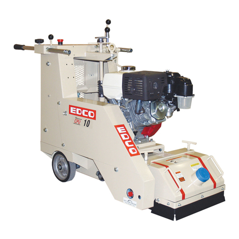
Edco 2PH-00 1-3/8 HEX User manual

2 PERSON POST HOLE DIGGERS
SKU # MODEL # POWER OPTION
87000 2PH-00 1-3/8 HEX HONDA GASOLINE ENGINE MODEL GXV160UH2N5AH
87001 2PH-00 7/8 SQUARE HONDA GASOLINE ENGINE MODEL GXV160UH2N5AH
READ AND UNDERSTAND THE OPERATOR’S SAFETY MANUAL THOROUGHLY
BEFORE ATTEMPTING TO OPERATE THIS EQUIPMENT.
Death or serious injury could occur if this machine is used improperly.
READ AND UNDERSTAND THE ENGINE MANUFACTURERS INSTRUCTIONS AND OPERATORS MANUAL BEFORE OPERATION.
OPERATOR’S INSTRUCTIONS & PARTS LIST
EDCO 2 PERSON POST HOLE DIGGER
MODEL: 2PH-00
MODEL: 2PH-00
Printed in USA
kjk ©2021
EQUIPMENT DEVELOPMENT COMPANY, INC.
100 Thomas Johnson Drive, Frederick, MD 21702-4600 USA
Phone: 800-638-3326 or 301-663-1600 • Fax: 800-447-3326 or 301-663-1607
E-EDCO-2MPH-0321
Starting Serial #: 032110000
See page 9 from Quick Start Guide

Page 2
E-EDCO-2MPH-0321
EQUIPMENT DEVELOPMENT CO., INC.
1
1•
800
800•
638
638•
3326
3326 EDCOINC.COM • T[email protected]
SAFETY INFORMATION
•Engine exhaust from this product contains chemicals
known to the State of California to cause cancer, birth
defects or other reproductive harm.
• 7LOWLQJ D JDVROLQH SRZHUHG PDFKLQH ¿WWHG ZLWK DQ
(3$DSSURYHGYHQWHGFKDUFRDO¿OWHUJDVFDSEH\RQG
20° can cause fuel leakage. If a leak occurs, do not
VWDUWRUUXQWKHHQJLQHXQWLOWKHOHDNLV¿[HG(OLPLQDWHDOORWKHULJQLWLRQ
VRXUFHVLQWKHLPPHGLDWHDUHDQRVPRNLQJÀDUHVVSDUNVRUÀDPHV
Use approved gasoline absorbing material to contain the fuel leakage.
Then use clean, non-sparking tools to collect absorbed materials then
GLVSRVHRIWKHVHFRQWDPLQDQWVSURSHUO\
•*DVROLQHLVH[WUHPHO\ÀDPPDEOHDQGSRLVRQRXV,WVKRXOG
RQO\EHGLVSHQVHGLQZHOOYHQWLODWHGDUHDVDQGZLWKDFRRO
engine.
• Small gasoline engines produce high concentrations of
FDUERQPRQR[LGH&2H[DPSOHD+3F\FOHHQJLQHRSHUDWLRQLQ
DQHQFORVHGFXIWDUHDZLWKRQO\RQHFKDQJHRIDLUSHUKRXU
LVFDSDEOHRISURYLGLQJGHDGO\FRQFHQWUDWLRQVRI&2LQOHVVWKDQ¿IWHHQ
minutes. Five changes of air in the same area will produce noxious
fumes in less than 30 minutes. Gasoline powered equipment should
QRWEHXVHGLQHQFORVHGRUSDUWLDOO\HQFORVHGDUHDV6\PSWRPVRI&2
poisoning include, head-ache, nausea, weakness, dizziness, visual
SUREOHPV DQG ORVV RI FRQVFLRXVQHVV ,I V\PSWRPV RFFXU JHW LQWR
IUHVKDLUDQGVHHNPHGLFDODWWHQWLRQLPPHGLDWHO\
• Never refuel a hot engine or an engine while it is running.
(QJLQHVDUHVKLSSHGIURPIDFWRU\ZLWKRXWIXHORLO
SAFETY MESSAGES
Indicates an imminent hazard which, if not avoided,
ZLOOUHVXOWLQGHDWKRUVHULRXVLQMXU\
Indicates an imminent hazard which, if not avoided,
FDQUHVXOWLQGHDWKRUVHULRXVLQMXU\
Indicates hazards which, if not avoided, could result in
VHULRXVLQMXU\DQGRUGDPDJHWRWKHHTXLSPHQW
•6DIHW\,QVWUXFWLRQVDUHSURFHHGHGE\DJUDSKLFDOHUWV\PERORI'$1*(5
:$51,1*RU&$87,21
GASOLINE / POWERED EQUIPMENT
DUST WARNING
(TXLSPHQW VKRXOG RQO\ EH RSHUDWHG E\ WUDLQHG SHUVRQQHO LQ JRRG
SK\VLFDOFRQGLWLRQ DQG PHQWDO KHDOWK QRWIDWLJXHG 7KH RSHUDWRUV
DQGPDLQWHQDQFHSHUVRQQHOPXVWEHSK\VLFDOO\DEOHWRKDQGOHWKHEXON
weight and power of this equipment.
• This is a TWO person tool. Maintain a safe operating distance to other
personnel. It is the operators’ UHVSRQVLELOLW\ to keep other people (work-
HUVSHGHVWULDQVE\VWDQGHUVHWFDZD\GXULQJRSHUDWLRQ%ORFNRႇ
WKHZRUNDUHDLQDOOGLUHFWLRQVZLWKURSLQJVDIHW\QHWWLQJHWF
)DLOXUHWRGRVRPD\UHVXOWLQRWKHUVEHLQJLQMXUHGE\À\LQJGHEULVRU
exposing them to harmful dust and noise.
7KLVHTXLSPHQWLVLQWHQGHGIRUFRPPHUFLDOXVHRQO\
)RU WKH RSHUDWRU¶V VDIHW\ DQG WKH VDIHW\ RI RWKHUV DOZD\V NHHS DOO
guards in place during operation.
• Never let equipment run unattended.
3HUVRQDO3URWHFWLRQ(TXLSPHQWDQGSURSHUVDIHW\DWWLUHPXVWEHZRUQ
ZKHQRSHUDWLQJ WKLV PDFKLQHU\ 7KHRSHUDWRU PXVW ZHDUDSSURYHG
VDIHW\HTXLSPHQWDSSURSULDWHIRUWKHMREVXFKDVKDUGKDWDQGVDIHW\
VKRHV ZKHQ FRQGLWLRQV UHTXLUH +HDULQJ SURWHFWLRQ 0867 EH XVHG
ZKHQRSHUDWLRQDOQRLVH OHYHOVRIWKLV HTXLSPHQWPD\ H[FHHG GE
(\HSURWHFWLRQ0867EHZRUQDWDOOWLPHV
GENERAL INSTRUCTIONS
.HHSERG\SDUWVORRVHFORWKLQJDQGDFFHVVRULHVDZD\IURP
moving parts. Failure to do so could result in dismember-
ment or death.
'RQRWPRGLI\WKHPDFKLQH
6WRSPRWRUHQJLQHZKHQDGMXVWLQJRUVHUYLFLQJWKLVHTXLSPHQW0DLQWDLQ
DVDIHRSHUDWLQJGLVWDQFHIURPÀDPPDEOHPDWHULDOV6SDUNV
IURPWKHFXWWLQJDFWLRQRIWKLVPDFKLQHFDQLJQLWHÀDPPDEOH
materials or vapors.
$OZD\VFRQWDFW\RXUDSSURSULDWHORFDODJHQFLHVWR
determine exact locations of all buried utilities and
VXEVXUIDFHKD]DUGV,IWKH('&23+FRPHVLQ
FRQWDFWZLWKDQ\VXEVXUIDFHKD]DUGSURSHUW\GDP-
DJHDQGRUSHUVRQDOLQMXU\ZLOORFFXU
5HDGDQGIROORZDOOVDIHW\GHFDOVDQGODEHOV
• Maintain a safe operating distance to other personnel.
%HIDPLOLDUZLWKDOODVSHFWVRIWKHPDFKLQH¶VRSHUDWLRQDQGFRQWUROV
EHIRUHDSSO\LQJSRZHUWRWKHHTXLSPHQW
8VHWKHFRUUHFWDFFHVVRU\IRUWKHMREEHLQJSHUIRUPHGDQGPDWHULDO
EHLQJUHPRYHG0DNHVXUHDFFHVVRULHVDUHPRXQWHGFRUUHFWO\
1HYHU RSHUDWH WKLV PDFKLQH ZKLOH XQGHU WKH LQÀXHQFH RI GUXJV RU
alcohol, while taking medications that impair the senses or reactions,
RUZKHQH[FHVVLYHO\WLUHGRUXQGHUVWUHVV
• Follow the instructions in the operator’s manual and exercise caution.
&RPSO\ZLWKDOOORFDOVDIHW\DQGKHDOWKUHJXODWLRQVDVZHOODV(3$DQG
26+$UHJXODWLRQV
5HDG0DLQWDLQDFRS\RIWKHHTXLSPHQW¶VRSHUDWRU¶VPDQXDODQGWKH
HQJLQHPRWRU PDQXIDFWXUHV RSHUDWRUV PDQXDO ZLWK WKH PDFKLQH IRU
reference at all times.
%HVXUHDOOGHFDOVRQWKHPDFKLQHFDQEHFOHDUO\UHDGDQGXQGHUVWRRG
5HSODFHZRUQPLVVLQJGHFDOVLPPHGLDWHO\
6RPHGXVWFUHDWHGE\SRZHUVDQGLQJVDZLQJ
grinding, drilling, and other construction activities
contains chemicals known to cause cancer, birth
defects, or other reproductive harm. Materials being removed can be
toxic or hazardous. A breathing respirator is required to help protect
the operator.
6RPHH[DPSOHVRIWKHVHFKHPLFDOVDUH
• Lead from lead-based paints.
&U\VWDOOLQHVLOLFDIURPEULFNVFRQFUHWHDQGRWKHUPDVRQU\SURGXFWV
Your risk of exposure to these chemi cals varies depending on how
RIWHQ\RXGRWKLVW\SHRIZRUN7RUHGXFH\RXUULVNZRUNLQDZHOO
YHQWLODWHGDUHDXVHDGXVWFRQWUROV\VWHPVXFKDVDQLQGXVWULDOVW\OH
YDFXXPDQGZHDUDSSURYHGSHUVRQDOVDIHW\HTXLSPHQWVXFKDVD
GXVWSDUWLFOHUHVSLUDWRUGHVLJQHGWR¿OWHURXWPLFURVFRSLFSDUWLFOHV
• See more on the importance of dust prevention and silica warnings
DWRVKDJRYVLOLFD
• More concrete and silica dust supression training and educational
PDWHULDOVDYDLDEOHDWHGFRLQFFRPVLOLFDVWDQGDUGV
:ULWWHQH[SRVXUHSODQVDUHSURYLGHGDWKWWSZZZHGFRLQFFRP
ZULWWHQH[SRVXUHFRQWUROSODQVGHIHFWVRURWKHUUHSURGXFWLYHKDUP
Materials being removed can be toxic or hazardous.

Page 3
EQUIPMENT DEVELOPMENT CO., INC.
1
1•
800
800•
638
638•
3326
3326 EDCOINC.COM • T[email protected]
E-EDCO-2MPH-0321
TABLE OF CONTENTS
Section Page Number
Safety Messages and General Instructions . . . . . . . . . . . . . . . . . . . . . . . . . . . . . 2
How To Order Replacement Parts . . . . . . . . . . . . . . . . . . . . . . . . . . . . . . . . . . . . 3
Saftey Symbols . . . . . . . . . . . . . . . . . . . . . . . . . . . . . . . . . . . . . . . . . . . . . . . . . . . 4-5
Saftey Guidelines. . . . . . . . . . . . . . . . . . . . . . . . . . . . . . . . . . . . . . . . . . . . . . . . . . 6
Maintenance Schedule . . . . . . . . . . . . . . . . . . . . . . . . . . . . . . . . . . . . . . . . . . . . . 7
Operating Controls. . . . . . . . . . . . . . . . . . . . . . . . . . . . . . . . . . . . . . . . . . . . . . . . . 8
Quick Start Guide. . . . . . . . . . . . . . . . . . . . . . . . . . . . . . . . . . . . . . . . . . . . . . . . . . 9
Operation Safety and Instructions . . . . . . . . . . . . . . . . . . . . . . . . . . . . . . . . . . . . 10
Starting the Machine. . . . . . . . . . . . . . . . . . . . . . . . . . . . . . . . . . . . . . . . . . . . . . . 11
Digging Safety and Instruction . . . . . . . . . . . . . . . . . . . . . . . . . . . . . . . . . . . . . . . 12-15
Maintenance/Service/Storage/Troubleshooting . . . . . . . . . . . . . . . . . . . . . . . . . . 16-19
Illustrations. . . . . . . . . . . . . . . . . . . . . . . . . . . . . . . . . . . . . . . . . . . . . . . . . . . . . . 20-25
Proposition 65 Warning . . . . . . . . . . . . . . . . . . . . . . . . . . . . . . . . . . . . . . . . . . . . 26
Warranty . . . . . . . . . . . . . . . . . . . . . . . . . . . . . . . . . . . . . . . . . . . . . . . . . . . . . . . 27
STOP, Before Use Warning . . . . . . . . . . . . . . . . . . . . . . . . . . . . . . . . . . . . . . . . . 28
HOW TO ORDER REPLACEMENT PARTS
• To insure product safety and reliability, always use
genuine EDCO replacement parts when making
repairs to the equipment.
• When calling for parts, specify the MODEL and
SERIAL number of the machine, which can be found
on the NAME PLATE. Keep that information in the
space provided. In addition to this information, give
part number, description, and quantity as listed on
the parts list to your parts representative.
• Please note: Due to improvements and changes
in the equipment, the illustrations shown may be
different than the actual machine.
FILL IN INFORMATION BELOW
Date of Purchase ______________________________
Model # _____________________________________
Serial # ______________________________________
SKU # ______________________________________
MODEL 2PH
OPERATOR’S INSTRUCTIONS & PARTS LIST MANUAL

Page 4
E-EDCO-2MPH-0321
EQUIPMENT DEVELOPMENT CO., INC.
1
1•
800
800•
638
638•
3326
3326 EDCOINC.COM • T[email protected]
This symbol means that the machine is heavy if the machine needs to be lifted onto or offof a truck,
loading dock etc. that proper technique or heavy duty lifting device should be used, personal injury could result.
(Yellow background with black pictogram and black outline)
This symbol means that dangerous chemicals, gases, dust particles and/or fumes are present including
carbon monoxide. Proper ventilation must be maintained. Do not use gasoline or diesel powered
equipment indoors.
(Yellow background with black pictogram and black outline)
This symbol means that there are sharp components and if feet/fingers/digits come in contact personal
injury or death could result.
(Yellow background with black pictogram and black outline)
This symbol means that potential hazardous voltages are present and the equipment must be properly
grounded and extreme caution should be taken. If for any reason maintenance or repair is needed,
insure that voltage(s) are disconnected at the machine and the source unless (be cautious) voltage needs
to be present to troubleshoot the problem, then only qualified personal should work on “live” systems.
(Yellow background with black pictogram and black outline)
This symbol means hazardous pressures are present. Caution should be exercised to prevent personal
injury or damage to equipment. Face, eye and head protection should be used.
(Yellow background with black pictogram and black outline)
This symbol means explosive and hazardous vapors are present. Caution should be exercised to
prevent personal injury to face and eyes. Breathing and personal protection should be used when
servicing.
(Yellow background with black pictogram and black outline)
This symbol means that the guards must remain in place while the engine/motor on the machine is
running because death or personal injury may result.
(Yellow background with black pictogram and black outline)
This symbol means that there are moving parts and if feet/fingers/digits are inserted under any edge of
the cutter/grinder/saw cover while the engine/motor on the machine is running that personal injury and loss
of foot/fingers/digits may result.
(Yellow background with black pictogram and black outline)
This symbol means the surface is HOT and that if fingers/digits/hands or any bare or unprotected skin comes
in contact with this surface or hot accessory, possible serious burns and personal injury may result.
(Yellow background with black pictogram and black outline)
SAFETY SYMBOLS

Page 5
EQUIPMENT DEVELOPMENT CO., INC.
1
1•
800
800•
638
638•
3326
3326 EDCOINC.COM • T[email protected]
E-EDCO-2MPH-0321
This symbol means that the Operator’s, owners, instruction and/or manufacturer(s) manuals must be
read and understood before operating or attempting to operate this electrical, gasoline, diesel or
propane powered equipment, failure to do so can result in personal injury and possible death.
(Blue background with white pictogram.)
This symbol means that proper eye protection must be worn/used during the operation of this equipment. There is
a potential risk of operator eye damage, injury or loss of sight. This also applies to any personnel standing
nearby observing the operation of this equipment.
(Blue background with white pictogram.)
This symbol means that proper ear protection should be worn/used during the operation of this equipment.
There is a potential risk of operator hearing damage, injury or loss of hearing which will increase based on the
length of exposure. This also applies to any personnel standing nearby observing the operation of this equipment.
(Blue background with white pictogram.)
This symbol means that proper head protection should be worn/used during the operation of this equipment there
is a potential risk of operator head injury from foreign or loose objects the equipment might come in
contact with during operation. This also applies to any personnel standing nearby or observing the
operation of this equipment.
(Blue background with white pictogram.)
This symbol means that proper breathing protection or engineering controls must be worn/used during the
operation of this equipment there is a potential risk of operator lung damage. Repeated and/or substantial
inhalation of airborne crystalline silica can cause serious or fatal respiratory diseases, including silicosis. In
addition, to California and some other authorities have listed respirable crystalline silica as a substance known
to cause cancer. When grinding/cutting/drilling such materials, always follow local respiratory precautions.
This also applies to any personnel standing nearby or observing the operation of this equipment.
(Blue background with white pictogram.)
This symbol means do not insert fingers/digits under any edge of the belt cover while the engine/
motor on the machine is running because personal injury and loss of fingers/digits may result.
(Black pictogram with red “No” symbol outline)
This symbol denotes the lifting point and means that if lifting of this equipment is necessary use a lifting
device that is designed to accomodate or exceed the weight of this machine. Check the Operator’s
manual for specifications. Using a device that is not designed to accomodate or exceed the weight of this
machine could result in damage to the machine and personal injury. Do not lift equipment over people
because death or serious injury could result.
(Blue background with white pictogram.)
This GHS pictogram identifies that the chemicals contained present serious health hazards.
(Black pictogram with red diamond symbol outline)
SAFETY SYMBOLS

Page 6
E-EDCO-2MPH-0321
EQUIPMENT DEVELOPMENT CO., INC.
1
1•
800
800•
638
638•
3326
3326 EDCOINC.COM • T[email protected]
Read and understand this Operator’s Instruction Manual,
and the Engine Manufacturer’s Owner’s Manual
before operating this equipment.
Death of serious injury can result if this machine is used improperly.
Safety Guidelines
Maintain a safe operating distance from flammable materials. Sparks from the cutting-action of this post hole digger can
ignite flammable materials or vapors.
Operator must wear appropriate clothing and footwear. Do not wear loose clothing or jewelry that can get tangled or
caught in moving parts.
Eye and ear protection must be worn at all times when this machine is in use. During normal use, sound levels can
exceed 85dBA. Use only ANSI approved safety glasses to help prevent eye injury. Everyday eyeglasses have only
impact resistant lenses; they are NOT safety glasses.
•Keep a safe operating distance from other personnel and never leave the machine running unattended.
•Maintain the machine in safe operating condition with all guards in place and secure, all mechanical fasteners tight, all controls in
working order and the EDCO 2PH configured for the job application.
•The 2PH in intended to dig vertical holes in uncolidated earth formations.
•The 2PH is to be operated by two operators, one operator holding two handles and the other holding the other two handles
•Inspect the auger carefully before installing. Do not use any questionable auger since serious personal injury and/or damage to prop-
erty can result.
•Never operate this post hole digger while under the influence of drugs, alcohol or when taking medications that impair the senses or
reactions, or when excessively tired or under stress.
•Always ensure a safe operting program for the post hole digger for the users has been established. This includes, but not limited to
OSHA requirements, local laws and regulations and always call before you dig to ensure no underground utilities are in the digging
zones.
•Incorrect use of the hole digger can result in property damage, personal injury or even death. To reduce this possibility, give complete
and undivided attention to the job at hand and follow these safety precautions.
Safety warnings and guidelines do not by themselves eliminate danger.
They are not given as substitutes for proper accident prevention and good judgement.

Page 7
EQUIPMENT DEVELOPMENT CO., INC.
1
1•
800
800•
638
638•
3326
3326 EDCOINC.COM • T[email protected]
E-EDCO-2MPH-0321
Maintenance Schedule
Repairs are to be
done by authorized
EDCO DEALERS
Read and follow instructions
in the Engine Manufacturer’s
Manual
Follow Engine
Manufacturer’s
Maintenance
Schedule
Visual Inspection of
Entire Machine X
Check Engine Oil* X
Change Engine Oil*
(Refer to Engine man-
ual) X
Change Transmission
Oil X
Clean Air Filter Element* X
Check/Replace Auger
Teeth & Tip X
Inspect Throttle
Assembly X
Before Each
Operation
Daily
Every 25 Hours
of Operation
As Required
* Consult Engine Operators/Owners Manual

Page 8
E-EDCO-2MPH-0321
EQUIPMENT DEVELOPMENT CO., INC.
1
1•
800
800•
638
638•
3326
3326 EDCOINC.COM • T[email protected]
EQUIPMENT DEVELOPMENT CO., INC.
OPERATING CONTROLS
MODEL 2PH POST HOLE DIGGER
Please Note:
Controls shown are for the model indicated.
The location of these controls may vary on the different models.
Due to improvements and changes in the equipment, the illustration shown may be different from the actual machine.
Throttle
Auger
Manual Choke Engage/Disengage
Auger Tip
Engine On/Off

Page 9
EQUIPMENT DEVELOPMENT CO., INC.
1
1•
800
800•
638
638•
3326
3326 EDCOINC.COM • T[email protected]
E-EDCO-2MPH-0321
EQUIPMENT DEVELOPMENT CO., INC.
QUICK START GUIDE
MODEL 2PH POST HOLE DIGGER
Fill Post Hole Digger Gearcase with Oil –
1. Wipe any dust/dirt from the oil filler plug and area around the oil fill plug. Oil Fill is located on
the side of the gear case (See figure 1), while the oil drain is located on the lower portion of the
gearcase near the driveshaft. Remove oil fill plug with 12 point, 1/2” socket to avoid stripping.
Replacement plugs are available to purchase, part number: 87024.
2. Using a funnel, pour in 1 quart of oil (High Grade SAE 30 Motor Oil, EDCO #: 87042, 1 quart
provided) in to the EDCO 2PH transmission gear case oil fill hole. The oil fill hole is in a location
designed to drain any oil over the 1 quart limit before replacing the oil fill plug.
3. Replace the oil fill plug securely.
Fill Engine with Oil –
1. Wipe any dust/dirt from the oil filler and area around the oil fill dipstick.
2. Using a funnel, pour in .65 Liter/.69 Quart of 4 stroke SAE 10W-30 Motor Oil (Not Provided)
in to the oil fill dipstick oil fill hole of the Honda GXV160 Engine.
3. Replace the oil fill dipstick securely.
Assemble Handle bars to gearcase –
1. Attached throttle cable control to handle bar. Slide handle bar in to throttle cable, with handle
bar material passing under the throttle lever, then out through the rectangular end. Locate throt-
tle control lever near the hand grip at a comfortable position. Default is facing away from opera-
tor for the throttle lever to be engaged by index and middle finger. Tigthen set screw on throttle
lever bracket. Do not overtighten as the plastic housing will crank with too much tension.
2. Attach the handle bar with the throttle cable utilizing the provided hardware, to the team
leader’s right hand side. Team leader should be positioned on opposite side of the recoil starter
pull cord direction. (See figure 2)
2. Attach the remaining three handle bars to the gear case utilizing the hardware provided.
*If the handle bar hardware holes do not match up perfectly between handle bar and hole in
gearcase, rotate handle bar 180° and try again.*
Engine Oil Fill/Dipstick
Gearcase/Transmission Oil Fill
Figure 1
Throttle
TEAM LEADER
POSITION
TEAM MEMBER
POSITION
Recoil
Starter
Figure 2

Page 10
E-EDCO-2MPH-0321
EQUIPMENT DEVELOPMENT CO., INC.
1
1•
800
800•
638
638•
3326
3326 EDCOINC.COM • T[email protected]
Operation
• The EDCO 2PH are not sealed or insulated. Do not operate this machine in an explosive atmosphere
or near combustible materials. Refer to current OSHA rules and regulations.
• The EDCO 2PH are designed for use by two operators. Use by more than two or fewer than two opera-
tors will cause confusion and loss of control, resulting in property damage and/or personal injury.
• Do not operate the EDCO 2PH with onlookers close by. The digging process can result in flying parti-
cles at high velocity and striking the operator and/or onlookers. This can result in property damage and/
or personal injury.
• Do not utilize any objects to remove loose soil in or around the hole area while the EDCO 2PH is in
use. Said object could become entrapped in rotating auger, leading to property damage and/or personal
damage.
• Always hold the operators handles firmly. Always determine handle bars and grips are in good working
condition and free of dirt/oil/grease/moisture. Never leave EDCO 2PH running unattended.
• Starting the EDCO 2PH should occur in the following process: Team leader regulates the engine speed
with the throttle control, while the team member starts the engine with the recoil starter. The team lead-
er is responsible for the verbal commands. Never operate the EDCO 2PH if it requires one person to be
responsible for all functions of the engine. This will result in loss of machine control leading to property
damage and/or personal injury.
• The EDCO 2PH is designed for two operators; (1) team member, to operate the recoil starter and the
choke control. (1) Team leader is responsible for throttle control regulation. (See figure 3)
• The EDCO 2PH operates by engaging the throttle control lever which in turn allows for the engine to
increase RPM that engages the featured centrifugal clutch, which only rotates at a designed speed.
The engine at idle will not engage the centrifugal clutch, meaning the auger will not rotate. If the throttle
control lever is not engaged the machine will not rotate.
• Stop engine with on board ON/OFF switch between each hole. Allowing the engine to operate between
each hole increases potential for property damage and/or personal injury.
• The EDCO 2PH is limited in the number of practical and/or suitable job applications. Site, surface con-
ditions, specifications and operator skill may dictate the need for a different type of machine/method to
achieve success while remaining safe.
Figure 3
Throttle
Recoil
Starter
TEAM LEADER
POSITION
TEAM MEMBER
POSITION

Page 11
EQUIPMENT DEVELOPMENT CO., INC.
1
1•
800
800•
638
638•
3326
3326 EDCOINC.COM • T[email protected]
E-EDCO-2MPH-0321
Starting the Machine Once the Auger
has Been Attached
Be sure the auger teeth and screw tip are not clogged. Removal of any obstructions before starting
the engine and digging operation will increase the effectivity of the auger and auger attachments
during use.
Place the EDCO 2PH in a vertical position over the desired hole location. Ensure both operators
have firm stances before starting the machine.
During all starting operations and processes ensure that at least three positions of the machine
are being supported by team member and team leader. At times during the starting process it is
required that the team member, has one hand completing an operation (choke, on/off, fuel valve)
and one hand on a handle bar. The team leader is required to maintain a majority of the stability of
the machine during these processes. Once the team member completes said operation, they are
responsible for replacing their hand on to the handle bars.
To Start:
1. Team member: open the gasoline breather to its most open position to ensure a continuous
steady flow of fuel. (See figure 4)
2. Team member: turn ON the engine kill switch. (See figure 5)
3. Team member: engages the choke control if required during cold starts. (See figure 6)
4. Team member: utilizes recoil starter to start the engine. If completing cold start, allow engine to
warm up before disengaging choke.
5. Team leader: operates the throttle control lever and provides stability during the starting opera-
tion.
DANGER! At NO time should the team leader begin engaging the throttle control lever until both
team leader and team member have all four handle bar positions supported. Before engaging the
throttle, ensure both team member and team leader have acknowledged to each other they have
full control and are ready to begin digging. Failure to comply, can result is personal injury and/or
property damage.
Figure 4 Figure 5 Figure 6

Page 12
E-EDCO-2MPH-0321
EQUIPMENT DEVELOPMENT CO., INC.
1
1•
800
800•
638
638•
3326
3326 EDCOINC.COM • T[email protected]
Digging
EDCO does not warranty or guarantee that this machine is suitable for specific job applications and
that it will have the required power to dig a specific diameter hole to a certain depth in a specific soil
type.
Before attempting to dig with the hole digger, determine any potential subsurface hazards which
may exist in the proposed digging location(s) including but not limited to: Rocks, roots, buried mate-
rials, pressurized pipes, electrical cables.
DANGER! Always contact your appropriate local agencies to determine exact locations of all buried
utilities and subsurface hazards. If the EDCO 2PH comes in contact with any subsurface hazard,
property damage and/or personal injury will occur.
The EDCO 2PH is designed to be operated and transported on/around the jobsite by two people.
Connect the auger to EDCO 2PH with the factory supplied clevis pin. When installing the clevis pin,
ensure the EDCO 2PH is tilted with the spark plug facing away from the surface, preventing oil and/
or gasoline to enter the combustion chamber causing a hydraulic lockup.
Do not connect the auger to the EDCO 2PH while the engine is running.
The factory supplied clevis pin is designed to withstand high stresses encountered under normal
digging operations. Use of any other connecting device including screws, bolts, pins, etc. can cause
property damage and/or personal injury.
Normal operation of the EDCO 2PH involves a large value of torque being transmitted and multiplied
within the gearcase/transmission. This energy is required to dig holes this machine is said to accom-
plish. In physics, there is always an opposite force to every force. Thus, if the auger encounters an
unknown or known obstruction this force will be transmitted to its stationary position (the operators).
The operators will feel a thrust of force, relative to the speed the auger is rotating, once the auger
has encountered said obstruction. This thrust of force is unavoidable while utilizing an EDCO 2PH.
To offset the velocity of forces felt during the immediate thrust of energy to the handle bar when en-
countering an obstruction, the operators should position themselves as close as possible to their left
handle bar. Keep upper arms as close to the upper body as possible to maximize mechanical body
leverage. Keep operators body and back in a most vertical posture as possible and always bend
at the legs to accomplish the digging operation. Avoid placing serious strains to the back and other
body members. Always lift in a straight line with your legs. Maintain vertical back posture. Avoid
bending wrist during the digging process.
Figure 7
Engine Off

Page 13
EQUIPMENT DEVELOPMENT CO., INC.
1
1•
800
800•
638
638•
3326
3326 EDCOINC.COM • T[email protected]
E-EDCO-2MPH-0321
Digging Continued
Positioning the left foot ahead of the right foot will increase the body leverage during the digging opera-
tion.
Maintain a steady and firm grip on the operator handle bars at all times.
CAUTION! Maintaining all of the above proper operating positions and operating controls is the most
important aspect to effective EDCO 2PH operation. Operator fatigue will occur while operating the
EDCO 2PH, following the above guidelines will increase the timeframe of when operator fatigue will
begin to occur.
The physical makeup of the composite handle bars allow for the handle bars to dampen and absorb
some of the energy exerted from the thrust when the auger encounters obstructions.
CAUTION! Do not operate if the handle grips are worn/damaged. Replace any grips that show wear or
have holes in the end caps.
EDCO Augers are designed for digging a wide variety of soil types and conditions. In soft soil (moist
or sandy) it might be necessary to hold up on the handle bars to resist the machine from screwing the
auger in to the ground. In soils with higher proctor densities it may be required of the operators to apply
some downward force on the handles to establish and maintain productive digging rates.
Digging with small diameter augers sometimes causes the auger to bury/bind itself or screw in to the
surface. This causes the EDCO 2PH to exceed past the designed operating power and overload the
clutch. Do not continue to overload or slip the clutch as this causes excessive heat transfer in the
gearcase and clutch assembly. Failure to stop operation when the auger becomes stuck can result in
property damage and/or personal injury.
If an auger becomes stuck, power OFF the unit, disconnect and remove the EDCO 2PH from the au-
ger, then remove the auger manually by several different industry accepted methods.
Do not attempt to create a pilot drilled hole with the auger, then come back and ream the hole with a
larger diameter auger. This will cause for unstable digging operation. Failure to comply will result in
property damage and/or personal injury.

Page 14
E-EDCO-2MPH-0321
EQUIPMENT DEVELOPMENT CO., INC.
1
1•
800
800•
638
638•
3326
3326 EDCOINC.COM • T[email protected]
When digging holes where known obstruction are present, allow the auger teeth to chip away the ob-
struction until the auger can pass by working the obstruction loose. This is usually accomplished by
applying upward pressure to the operator handles. At times the obstruction is too large to remove with
the EDCO 2PH, continued use or attempts to remove the obstruction will result in machine damage and
increase operator fatigue. Instead, remove the auger and EDCO 2PH, then remove obstruction with a
shovel or other digging tool.
When retracting or removing the auger and EDCO 2PH after the desired hole depth has been achieved,
allowing the auger to slowly rotate will ease the removal of the auger. However, this will also leave some
soil to be manually removed from the bottom of the hole.
Stop the EDCO 2PH engine in between each hole. Failing to do so can cause property damage and/or
personal injury.
To stop/turn offthe EDCO 2PH:
1 - Team leader: Release the throttle control lever and allow the engine to idle. If the throttle is function-
ing properly the engine will go to idle speed and the clutch will disengage causing the auger to stop
rotation. If this does not occur, check the throttle control, throttle linkage and idle speed adjustment on
engine. There may be some auger rotation at idle speed due to drag in the clutch assembly. This does
not mean the clutch is engaged.
2- Team member: turn the ON/OFF engine switch to the OFF position. (See figure 8)
When you are done operating the machine, turn the fuel valve to the offposition (See figure 9) to mini-
mize the possibility of fuel seepage in to the combustion chamber. Property damage can occur if the fuel
valve is left open and the engine is tilted to allow fuel in to the crankcase.
Digging Continued
Figure 8 Figure 9

Page 15
EQUIPMENT DEVELOPMENT CO., INC.
1
1•
800
800•
638
638•
3326
3326 EDCOINC.COM • T[email protected]
E-EDCO-2MPH-0321
Digging With an Auger Extension
Some applications require additional hole depth beyond the capabilities of a standard EDCO Auger.
This is accomplished by utilizing an EDCO auger extension. The addition of auger extensions re-
quire additional operator skill and common sense. Each operator must determine they are competent
enough to operate the EDCO 2PH with an auger extension attached.
1. Dig to the acceptable full depth of the standard auger. Remove as much of the soil from the hole
as possible.
2. Stop the EDCO 2PH, turn the fuel valve to the offposition. Disconnect the engine spark plug.
3. Place the unit back in to the dug hole.
4. Disconnect the EDCO 2PH from the standard auger and set aside on a level/horizontal surface,
leaving the auger in the hole.
5. Attach the auger extension to the auger that is located in the hole. Secure the auger extension with
the supplied clevis pin.
6. Install the EDCO 2PH to the auger extension.
7. Follow the instruction for starting and operating the EDCO 2PH. Extra caution and skill is required
to start an begin the continued digging with an EDCO 2PH starting in the existing hole.
There is a maximum allowable limit of one (1) auger extension when utilizing an EDCO 2PH. Failure
to comply will result in property damage and/or personal injury.
After the desired depth is achieved while using the auger extension, stop the engine, turn fuel valve
offand disconnect the spark plug.
1. Lift the EDCO 2PH and auger/extensions up far enough out of the hole so that the auger exten-
sion is above ground level. Utilizing blocking or auger fork supporting the standard length auger in the
hole.
2. Disconnect the EDCO 2PH from the auger extension and set the unit aside on a level, horizontal
surface. (This may require an additional team member to support EDCO 2PH and auger/extension)
3. Disconnect the auger extension from the standard length auger.
4. Then remove the standard length auger from the hole.
DANGER! Do not attempt to start the EDCO 2PH with an auger and auger extension attached out of
an existing hole. Always dig with the standard length auger first, then attach extension as prescribed
in the above text. If these instruction are not followed, property damage and personal injury will occur.

Page 16
E-EDCO-2MPH-0321
EQUIPMENT DEVELOPMENT CO., INC.
1
1•
800
800•
638
638•
3326
3326 EDCOINC.COM • T[email protected]
Maintenance
Always wear proper personal protective equipment while servicing or maintaining equipment. If
you are not competent in doing the work, please reach out to EDCO for advice or where you might
be able to have your machine serviced.
Changing the EDCO 2PH transmission oil (Interval: 25 hours)
The process requires a level working platform and appropriate working height surface. The EDCO
2PH can also be supported in a vise clamped on to the driveshaft.
1. The transmission oil should be changed as needed or at least every 25 hours of use.
2. Wipe any dust/dirt from the oil filler plug and area around the oil fill plug. Oil Fill is located on the
side of the gear case, while the oil drain is located on the lower portion of the gearcase near the
driveshaft. (See Figure 10)
3. Remove the fill plug using a 12 point, 1/2” socket to avoid stripping. Doing this while draining
the oil through the drain plug will allow for steady flow during the oil draining process.
4. Remove the drain plug with an 12 point, 1/2” socket and allow for oil to drain in to a suitable
container. Dispose of the oil based on local ordinances. Once oil has drained completely, replace
the oil drain plug securely.
5. Using a funnel, pour in 1 quart of oil (High Grade SAE 30 Motor Oil, EDCO #: 87042) in to the
EDCO 2PH transmission gear case oil fill hole. The oil fill hole is in a location designed to drain
any oil over the allowed 1 quart limit before replacing the oil fill hole. It is important to allow for any
excess oil to drain before reinstalling the oil fill plug.
6. Replace the oil fill plug securely.
Replacing Auger Screw Bit
Replace as required.
While replacing the screw bit, inspect the entire auger for cracks, bent axle or any other possible
damage before replacing parts.
1. Using two 1/2” wrenches, remove the screw and nut holding the screw bit to the drive lug. Re-
move the bit and dispose.
2. Inspect the drive lug, if drive lug needs replaced this can be cut offusing suitable cut offtools or
torch.
3. Replace Auger screw bit with new screw bit and hardware. Tightly fasten with wrenches.
Replacing Auger Teeth
Replace as required.
While replacing auger teeth, inspect the entire auger for cracks, bent axle or any other possible
damage before replacing parts.
Figure 10
Oil Drain
Oil Fill

Page 17
EQUIPMENT DEVELOPMENT CO., INC.
1
1•
800
800•
638
638•
3326
3326 EDCOINC.COM • T[email protected]
E-EDCO-2MPH-0321
Maintenance Continued
There are a multitude of auger teeth available on the market. All of them have different capabilities
and different lifespans. Most all of the teeth available are interchangeable across all manufacturers
of augers.
1. Using a hammer and punch, strike the rear of the tooth accessed through the shank plate teeth
access hole until the tooth has come dislodged from the shank plate.
2. Remove any residual rubber from the core of the tooth that may have stuck to the shank plate
over time.
3. Inspect the shank plate and the tooth cavity for any fatigue and wear. If required the shank plate
can be replaced.
4. Install new tooth in to the tooth pocket utilizing a soft tip mallet. Ensure tooth is completely seat-
ed in the pocket. Do not use metal hammer to accomplish this task.
Engine Maintenance and Troubleshooting
Consult the engine operators and owner’s manual for proper engine service and maintenance
manuals.
The engine ON/OFF switch (PN: 54004) located on the tan sheet bracket (PN: 101139) is are
EDCO parts and can only be purchased from EDCO.
The choke bracket (Honda: 16598-Z1V-G00, EDCO: 87011) and choke engage rod (Honda:
16611-Z1V-G00, EDCO: 87012) are Genuine Honda parts, however these parts can be purchased
through EDCO.
Ensure Engine ON/OFF switch and fuel valve are in proper positions based on the starting and
stopping instruction listed in this manual.
Troubleshooting EDCO 2PH
• Engine bogs down and will not rotate driveshaft upon engaging throttle: clutch is locked up or
seized
• Clutch engages at idle speed, or auger rotates at idle speed: Centrifugal clutch is worn out
• Clutch engages at idle speed, or auger rotates at idle speed: Throttle linkage is adjusted improp-
erly
• Clutch engages at idle speed, or auger rotates at idle speed: Engine idle speed is not set correctly
• Hole Digger is not digging or “lacking power” to accomplish task: Centrifugal clutch is worn out
• Hole Digger is not digging or “lacking power” to accomplish task: Auger diameter is too large for
soil

Page 18
E-EDCO-2MPH-0321
EQUIPMENT DEVELOPMENT CO., INC.
1
1•
800
800•
638
638•
3326
3326 EDCOINC.COM • T[email protected]
Maintenance/Repair/Storage/Transportation
Use only genuine, approved, replacement parts and accessories for replacement and repair.
Always properly maintain the EDCO 2PH. Check all fasteners and individual parts prior to every
operation. Designed safety features are only effective if they are maintained and in good working
order. All maintenance should be completed by a competent and trained technician or service facil-
ity. If proper maintenance is not performed, personal injury and/or property damage will occur.
Review the engine throttle control and throttle cable linkages and ensure they are not damaged and
allow for complete range of motion as designed.
Do not operate the EDCO 2PH with a faulty or damaged throttle control and throttle cable linkage.
If any decal becomes damaged and/or illegible, replace with genuine, factory replacement decals
only.
Replace the auger teeth and screw tip when signs of excessive wear become apparent. When
these components are not replaced, the boring head and auger flighting will begin to wear, causing
an inverted cone auger reducing productivity and potential property damage and/or personal injury.
The EDCO 2PH utilizes handle bars specially designed to reduce weight and help absorb the shock
loads transmitted to the operator during the digging process. This material is not as abrasion re-
sistant as steel and cannot handle the same amount of surface damage as steel. Do not allow the
handle bar material to come in to contact with sharp objects. Keep handles clean and free of dirt
and moisture.
Do not utilize chains or slings strapped around the handle bar material to help remove a stuck
EDCO 2PH. This will cause damage to the handle bar material and to the transmission.
EDCO 2PH handle bars have a maximum service life of 6 years.
DANGER! The composite handle bar material does not eliminate the potential for property damage
or personal injury if the machine is to contact an electrical cable.
Torque Chart
Description Torque Specification
Driveshaft Nut
Illustration 1, Item 5 (Qty: 1) 60 Foot Pounds (81 N.m)
Gearcase Fasteners
Illustration 2, Item 23, 24 (Qty: 10) 20 Foot Pounts (27 N.m)

Page 19
EQUIPMENT DEVELOPMENT CO., INC.
1
1•
800
800•
638
638•
3326
3326 EDCOINC.COM • T[email protected]
E-EDCO-2MPH-0321
Maintenance/Repair/Storage/Transportation
Storage on the Jobsite (temporary)
There are three acceptable methods to storing the EDCO 2PH on the jobsite. If other methods
are used, property damage and/or personal damage will occur. Always store the machine with
the engine ON/OFF switch in the offposition and the fuel valve in the offposition.
1. Leave the EDCO 2PH and auger connected, then dig a shallow hole or place the unit in a pre-
existing dug hole that will support the EDCO 2PH and auger in a vertical position.
2. Leave the EDCO 2PH and auger connected (no extension), tilt the machine and rest on the
two handle bars opposite of the spark plug (spark plug facing up).
3. Disconnect the EDCO 2PH from the auger and/or auger extension. Set the EDCO 2PH on to a
level/horizontal surface
Engine On
Figure 2
Engine Off
Figure 1
Transporting:
When transporting an EDCO 2PH the gasoline breather vent must be completely closed to elimi-
nate potential fuel seepage and fire hazards.
Always transport the machine to the job site without the auger attached.
Failure to transport the machine in a vertical manner, disconnected from the auger, can cause
gearcase oil to become trapped in the centrifugal clutch causing excessive slippage in the clutch
assembly diminishing the service life of the clutch assembly.

Page 20
E-EDCO-2MPH-0321
EQUIPMENT DEVELOPMENT CO., INC.
1
1•
800
800•
638
638•
3326
3326 EDCOINC.COM • T[email protected]
ILLUSTRATION 1: GEARBOX GROUPING
This manual suits for next models
2
Table of contents
Other Edco Lawn And Garden Equipment manuals