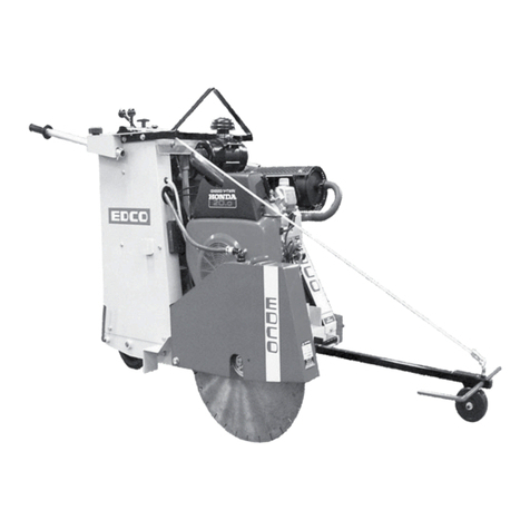
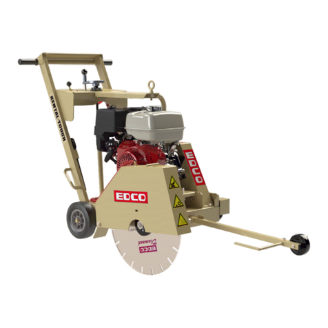
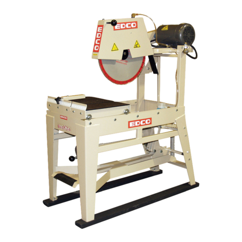
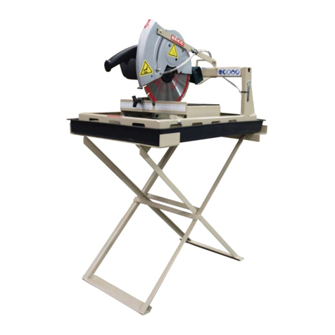
Edco GMS-14A Assembly instructions

Printed in USA
© 2002
Page 1
E-GMS14A-I-0402
100 Thomas Johnson Drive, Frederick, MD 21702-4600 USA
Phone (301) 663-1600 • 1-800-638-3326
Fax (301) 663-1607 • 1-800-447-3326
Website: www.edcoinc.com • Email: [email protected]
Operator’s Instruction Manual
GMS-14A
14” Gasoline Powered Masonry Saw
with Controlled Dust Operation
Shown with optional
Stand

Printed in USA
© 2002
Page 2
E-GMS14A-I-0402
100 Thomas Johnson Drive, Frederick, MD 21702-4600 USA
Phone (301) 663-1600 • 1-800-638-3326
Fax (301) 663-1607 • 1-800-447-3326
Website: www.edcoinc.com • Email: [email protected]
Read and understand these instructions thoroughly before
attempting to operate this equipment.. Different models
have different parts and controls, death or serious injury
could occur if the machine is used improperly.
•Equipment should only be operated by trained personnel in good
physical condition and mental health (not fatigued). The operator
and maintenance personnel must be physically able to handle the
bulk weight and power of this equipment.
•This is a one person tool. Maintain a safe operating distance to
other personnel. It is the operators’ responsibility to keep other
people (workers, pedestrians, bystanders, etc.) away during opera-
tion. Block off the work area in all directions with roping, safety
netting, etc. for a safe distance. Failure to do so may result in others
being injured by flying debris or exposing them to harmful dust and
noise.
•This equipment is intended for commercial use.
•For the operators safety and the safety of others, always keep all
guards in place during operation.
•Never let equipment run unattended.
•Personal Protection Equipment and proper safety attire must be
worn when operating this machinery. The operator must wear ap-
proved safety equipment appropriate for the job such as hard hat
and safety shoes when conditions require. Hearing protection MUST
be used (operational noise levels of this equipment may exceed
90db) . Eye protection MUST be worn at all times. Adust/particle
respirator must be used when cutting or grinding without an ad-
equate dust control system in place.
Keep body parts and loose clothing away from moving parts.
Failure to do so could result in dismemberment or death.
•Do not modify the machine. Use only genuine EDCO parts and
accessories. Repairs and service should be performed by EDCO or
by approved EDCO dealers or repair technicians.
•Stop motor/engine when adjusting or servicing this equipment.
Maintain a safe operating distance from flammable
materials. Sparks from the cutting-action of this machine can
ignite flammable materials or vapors.
•Always keep all guards in place during operation for the operators’
safety and the safety of others.
READ AND UNDERSTAND THE OPERATORS INSTRUCTION MANUAL THOROUGHLY
BEFORE ATTEMPTING TO OPERATE THIS EQUIPMENT.
Death or serious injury could occur if this machine is used improperly.
Engine exhaust from this product contains
chemicals known to the State of California to cause
cancer, birth defects or other reproductive harm.
• This equipment will create dust from the material being removed.
That dust may contain chemicals known to the State of California to
cause cancer and/or birth defects or other reproductive harm. Check
the chemical properties of the material to be removed and take the
appropriate precautions.
• Extreme care must be taken when operating electric
models with water present: Ensure power cord is prop-
erly grounded, is attached to a Ground-Fault-Interrupter
(GFI) outlet, and is undamaged.
• Check all electrical cables - be sure connections are tight and
cable is continuous and in good condition. Be sure cable is cor-
rectly rated for both the operating current and voltage of this equip-
ment.
Improper connection of the equipment-grounding
conductor can result in a risk of electric shock.
Check with qualified electrician or service person if
there is any doubt as to whether the outlet is properly
grounded. Adhere to all local codes and ordinances.
•NOTE: In the event of a malfunction or breakdown, grounding pro-
vides a path of least resistance for the electric current to dissipate.
The motor is equipped with a grounded plug and must be connected
to an outlet that is properly installed and properly grounded. DO
NOT modify the plug provided on the motor. If the plug does not fit
the outlet have a qualified electrician install the proper receptacle.
• Switch motor OFF before disconnecting power.
• Do not disconnect power by pulling cord. To disconnect, grasp the
plug, not the cord.
• Unplug power cord at the machine when not in use and before
servicing.
Engine exhaust from this product contains chemicals known
in certain quantities, to cause cancer, birth defects or other
reproductive harm.
• Gasoline is extremely flammable and poisonous. It should only be
dispensed in well ventilated areas, and with a cool engine.
Do not operate gasoline powered equipment with-
out adequate ventilation. Carbon monoxide is an
invisible, odorless gas that can kill.
SAFETY
MESSAGES
EXHAUST HAZARD
GENERAL INSTRUCTIONS
SAFETY MESSAGES
GASOLINE POWERED EQUIPMENT
ELECTRICAL POWERED EQUIPMENT
• Safety Instructions are proceeded by a graphic alert
symbol of DANGER, WARNING, or CAUTION.
Indicates an imminent hazard which, if not avoided,
will result in death or serious injury.
Indicates an imminent hazard which, if not avoided,
can result in death or serious injury.
Indicates hazards which, if not avoided, could result
in serious injury and or damage to the equipment.

Printed in USA
© 2002
Page 3
E-GMS14A-I-0402
100 Thomas Johnson Drive, Frederick, MD 21702-4600 USA
Phone (301) 663-1600 • 1-800-638-3326
Fax (301) 663-1607 • 1-800-447-3326
Website: www.edcoinc.com • Email: [email protected]
Equipment Instruction Manual
EDCO GMS-14A
HOW TO ORDER REPAIR PARTS
To insure product safety and reliability, always use genuine EDCO replace-
ment parts when making repairs to the equipment.
When ordering parts, please specify the MODEL and SERIAL NUMBER of
the machine as given on the NAMEPLATE. In addition, give part number,
description and quantity as listed on the parts list.
Please note: Due to improvements and changes in the equipment the illustra-
tions shown may be different from the actual machine.
Toll Free: Voice 1-800-638-3326 • Fax 1-800-447-3326
Figure 1
Section Page Number
Table of Contents
Safety Guidlines.....................................................................................................................4
Operating Instructions....................................................................................................5-7
Maintenance...................................................................................................................8-10
Maintenance Schedule..........................................................................................................11
Limited Equipement Warranty................................................................................................12
Note: Dimensions and Specifications for the GMS14A
are approximate and subject to change.
Height
Width
Length
36”
26 1/2”
40”
91.5cm
67.3cm
101.6cm
Overall Dimensions
without optional stand
Shown with optional
“Folding Table”
Optional “ProCart”
not shown
67 1/2 171.5cm
26 1/2”
67.3cm
24”
60.9cm
40”
101.6cm
47”
119.4cm
31 1/2” 80cm
36” 91.5cm

Printed in USA
© 2002
Page 4
E-GMS14A-I-0402
100 Thomas Johnson Drive, Frederick, MD 21702-4600 USA
Phone (301) 663-1600 • 1-800-638-3326
Fax (301) 663-1607 • 1-800-447-3326
Website: www.edcoinc.com • Email: [email protected]
Safety Guidelines
Eye and ear protection must be worn at all times while the GMS-14A is in use. During normal opera-
tion, sound pressure levels exceed 92dBA. Use only ANSI approved safety glasses to help prevent eye
injury. Everyday eyeglasses have only impact resistant lenses; they are NOT safety glasses.
Operator must wear appropriate clothing and footwear. Do not wear loose clothing or jewelry that can
get tangled in moving parts. Footwear should provide sure footing and protection from debris that may
be dropped. Take steps to be sure hair will not be caught in moving parts. If necessary, tie it back.
Disconnect the spark plug wire lead before performing any service on the machine. (Figure 4, Item W)
• When loading or unloading the saw, use caution. Make sure rolling table is locked so that the blade will not be
damaged. (Figure 3, Item O) Do not move the saw while the engine is running.
• This unit is shipped new from the factory without oil or gasoline, it will need to be added before it is used. Check the
Engine Manufacturer’s Owner’s Manual for instructions on break-in, servicing and use of engine.
This GMS-14A gasoline powered saw is designed to be used in areas where electrical power is not
available. Do not operate gasoline-powered equipment without adequate ventilation. The exhaust fumes
contain carbon monoxide, an invisible, odorless gas that can kill.
This machine is designed to cut interlocking pavers, retaining wall block and brick. The work piece must
be placed on the rolling table surface and the table used to move the work piece to the blade. Cut only
in a straight line. Do not force or twist the work piece into the blade. Personal injury or damage to the
equipment or blade can result.
• Never exceed the maximum operating speed of the blade. Match the blade speed rating with the arbor shaft speed.
(See page 9)
• Never leave the saw running unattended.
•Never operate this saw under the influence of drugs, alcohol or when taking medications that impair the senses or
reactions, or when excessively tired or under stress.
• Make sure all safety decals can be clearly read and understood. Replace damaged or missing decals immediately.
Safety warnings and guidelines do not by themselves eliminate danger.
They are not given as substitutes for proper accident prevention procedures and good judgement.
Read and understand this Operator’s Instruction Manual,
and the Engine Manufacturer’s Owner’s Manual
before operating this equipment.
Death of serious injury can result if this machine is used improperly.

Printed in USA
© 2002
Page 5
E-GMS14A-I-0402
100 Thomas Johnson Drive, Frederick, MD 21702-4600 USA
Phone (301) 663-1600 • 1-800-638-3326
Fax (301) 663-1607 • 1-800-447-3326
Website: www.edcoinc.com • Email: [email protected]
Operating Instructions
Diagrams shown with Honda Cyclone Dual-Filter Element Engine as an example.
Consult the Engine Manufacturer’s Owner’s Manual for information on specific models.
V. Muffler
W. Spark Plug Lead
X. Oil Drain
Y. Dip Stick/Filler Cap
Figure 4
V
X
Y
W
O. Blade Guard Level Rod
P. Back Stop
Q. Water Pump Primer Bulb
R. Right Angle Guide Bar
S. Blade Guard
T. Water Pump
U. Optional Table
O
Figure 3
P
Q
R
S
U
T
A. Air Filter
B. Fuel Tank
C. On/Off Switch
D. Recoil Starter
E. Cyclone Housing
F. Engine Throttle
G. Choke
H. Fuel Valve Lever
I. Water Hose
J. Belt Guard
K. Diamond Blade
L. RollingTable
M. Water Tray
N. Water Tray Drain/Plug
EF
G
H
Figure 2
CJ
M
B
A
D
I
K
N
L

Printed in USA
© 2002
Page 6
E-GMS14A-I-0402
100 Thomas Johnson Drive, Frederick, MD 21702-4600 USA
Phone (301) 663-1600 • 1-800-638-3326
Fax (301) 663-1607 • 1-800-447-3326
Website: www.edcoinc.com • Email: [email protected]
Before Starting Engine:
•Read and understand the instructions supplied by the engine manufacturer.
• Familiarize yourself with all engine and saw controls. (Figures 2-4)
• Visually inspect the entire machine for damage or wear. Look for signs of oil or fuel leaks. Remove excess dirt or debris.
Check that all nuts, bolts and screws are tightened. Check for proper alignment of moving parts, possible binding of
moving parts, breakage of parts, loose mounting brackets, and any other condition that might affect operation.
• Inspect diamond blade and arbor shaft. Check blades for cracks, loose segments, worn or out-of-round arbor holes.
Do not use warped, twisted, out-of-balance blades or any blade of questionable condition. (Figure 8)
• Check engine oil. Make sure that it is at the proper level and that it is clean.
Note: Some engines have an Oil Alert System that will automatically stop the engine before the oil level falls below the
safe limit. To avoid an unexpected shut down, check the oil level regularly during operation.
• Check the fuel level. Do not over fill fuel tank and never refuel a hot engine. If refueling is necessary during operation,
allow engine to cool down first.
•Inspect the air filter to be sure it is clean.
• If wet cutting, fill the water tray with water. The water pump recycles the water from the tray, plug the drain hole and be
sure the water is circulating from the tray to the water pump.
• If wet cutting, with an external source of water, such as a water barrel, open the drain plug in the water tray and make
sure the water has somewhere to go that is clear of the working area. One option is to hook up a second hose. (Figure
6)
• If dry cutting, attach a vacuum to the end of the optional dust lood. (Figure 7)
Note: While the GMS-14A was designed to be used with a standard shop vac, EDCO recommends using a heavy duty
vacuum such as the VAC-150. The VAC-150 has the advantage of a Self-Purging System to help keep concrete dust
from building up on the filter and a larger filter area to maintain performance during use, thus reducing time wasted on
frequently cleaning a standard shop vac and filter media.
Figure 6
Figure 5 Figure 7

Printed in USA
© 2002
Page 7
E-GMS14A-I-0402
100 Thomas Johnson Drive, Frederick, MD 21702-4600 USA
Phone (301) 663-1600 • 1-800-638-3326
Fax (301) 663-1607 • 1-800-447-3326
Website: www.edcoinc.com • Email: [email protected]
Starting the Engine:
• Be sure blade is clear of item to be cut.
• Determine that the recoil starter assembly turns freely, starter rope pulls easily, and the rope retracts properly.
• Follow the instructions supplied in the engine manufacturer’s Owner’s Manual for starting engine.
• Open the throttle and allow engine to reach operating temperature.
Note: To ensure that the necessary power is transferred to the blade, all cutting must be done at full throttle. The
governor is factory set for correct speed - altering this setting will damage the machine. Maintain the engine according
to factory specifications.
Cutting:
• Place the work piece on rolling table against the backstop and use the rolling table to move the work piece to the
blade. Do not strain the engine while cutting or jam work piece into the blade. Do not twist the work piece while
cutting.
• Do not reach underneath or around work piece while the blade is rotating.
• Keep stable footing at all times while cutting.
Keep hair, clothing, fingers and all body parts away from the blade and any other moving parts.
• For wet cutting, maintain an adequate supply of water to cool the blade.
Note: If using the optional water pump, clean water must be run through the cycle daily to avoid build up in the
pump.
• When you have finished cutting, return throttle to idle. Stop the engine by returning the engine mounted stop switch
to the OFF position. Do not leave the saw running unattended.
•Clean dust and debris from entire machine.
IMPORTANT REMINDER: This machine is designed to use diamond blades to cut pavers, stone, tile,
masonry products and brick. Do not use it to cut anything else.
Possible Diamond Blade Problems
Figure 8
Refer to the
Rx for Diamond Blades
for more detailed information
on diamond blades.

Printed in USA
© 2002
Page 8
E-GMS14A-I-0402
100 Thomas Johnson Drive, Frederick, MD 21702-4600 USA
Phone (301) 663-1600 • 1-800-638-3326
Fax (301) 663-1607 • 1-800-447-3326
Website: www.edcoinc.com • Email: [email protected]
Changing the Blade:
• Inspect the new blade thoroughly before installing. Check for cracks, loose segments, worn or out-of-round arbor
holes. Refer to the Rx for Diamond Blades pamphlet provided with your blade for more detailed information on
inspecting blades. Be sure the blade is appropriate for the job and matches the arbor speed and mounting
configuration on this saw. (See page 9)
The GMS-14A was designed to be used with diamond saw blades
Step One:
Remove spark plug lead from spark plug.
Pull the rolling table all the way to the front of the machine.
Adjust and lock the blade/blade guard assembly into a comfortable working position as
shown in (Figure 9).
Step Two:
Remove bolt and blade cap using a SAE
3/4” wrench (Figures 10 & 11) Carefully
remove old blade. Inspect arbor shaft,
backing plate and blade guard while
blade is off. Clean if dirty or replace if
damaged or worn.
Step Three:
Look for “direction of rotation” markings on the blade.
(Usually an arrow stamped on the blade.) Place new blade on
the arbor shaft verifying that once installed the markings on the
blade follow the proper direction of rotation. (Figure 13)
Reinstall blade cap and tighten bolt using a SAE 3/4” wrench.
If moved in step #1, reposition blade/blade guard assembly and
tighten. Reconnect spark plug lead.
Maintenance
Disconnect spark plug lead before performing
any maintenance on this machine.
Figure 13
Figure 12
Figure 10
Consult the Engine Manufacturer’s Owner’s Manual for more detailed engine maintenance instructions.
Figure 11
Figure 9

Printed in USA
© 2002
Page 9
E-GMS14A-I-0402
100 Thomas Johnson Drive, Frederick, MD 21702-4600 USA
Phone (301) 663-1600 • 1-800-638-3326
Fax (301) 663-1607 • 1-800-447-3326
Website: www.edcoinc.com • Email: [email protected]
Belt Adjustment and Replacement:
• Periodically check to be sure the belts are undamaged and that they are at the proper tension. Slipping belts will
overheat causing the cutting speed to be limited, shortening the life of the belts. Over-tensioned belts will shorten the
life of the belts & bearings.
• On new equipment and after installing new belts, be certain to re-tension the belts after the first 4 hours of use. New
belts are stiff and require a break in period. Belts that become loose could slip and/or overheat.
• Damaged, stretched or excessively worn belts should be replaced with a new complete set of belts.
IMPORTANT: Belts must be replaced as a set, even if only one belt is showing wear.
Remove belt guard (3 bolts) and inspect belts. A straight edge is a
good tool to use to be certain sheaves are even and properly aligned.
(Figure 14)
To tension belts, back off blade head assembly
bearing bolts(4) and slide the blade head assembly
forward or back until belts are at proper tension.
(Figure 15) NOTE: Be sure to align blade after belt
adjustment or belt replacement
To remove belts, back off bearing mounting bolts (4),
slide blade head assembly forward or backward
until belts slide off the sheaves.Place a complete
set of new belts on the machine. Realign blade
head assembly then tighten bolts.Reinstall belt cover.
Figure 14
Blade Diameter
Arbor Shaft Diameter
Max Cutting Depth
Arbor Speed
14 inches
1”
4 1/2”
3600 RPM
Use Diamond Blades Only
Clean Wheels on Rolling Table:
During daily visual inspection, check to be sure the wheels on the rolling
table move smoothly and that there is no debris in the wheel tracks.
(Figure 16)
No lubrication is necessary for the wheels because of sealed bearings.
Replace damaged or worn wheels.
Figure 16
Figure 15
Bearing
Mounting
Bolts
Rear View
Sealed bearings

Printed in USA
© 2002
Page 10
E-GMS14A-I-0402
100 Thomas Johnson Drive, Frederick, MD 21702-4600 USA
Phone (301) 663-1600 • 1-800-638-3326
Fax (301) 663-1607 • 1-800-447-3326
Website: www.edcoinc.com • Email: [email protected]
Change Engine Oil:
• Check Engine Oil before each operation. Open the filler cap and look at the dip stick. (Figure 17) Oil should be
clearly visable both on the stick and in the cavity and should look fairly clean. Running the machine on dirty oil or
when the oil is low will result in damage to the equipment.
• Change the Engine Oil after every 50 hours of operation or sooner as conditions require. Refer to the Engine
Manufacturer’s Owner’s Manual for specific viscosity recommendations and changing instructions.
Inspect and Clean Oil Air Filter:
Shown with Honda Cyclone Dual Filter style element.
Outer foam filter (Figure 19) is removable for cleaning.
Refer to the Engine Manufacturer’s Owner’s Manual
for instructions on specific models.
Check air filter at least once daily. (Figure 20)
Dirt build up on the filter will cause the engine to wear out faster.
Figure 19
Figure 17
Figure 20
Figure 18
Oil Drain
Dip Stick/
Filler Cap

Printed in USA
© 2002
Page 11
E-GMS14A-I-0402
100 Thomas Johnson Drive, Frederick, MD 21702-4600 USA
Phone (301) 663-1600 • 1-800-638-3326
Fax (301) 663-1607 • 1-800-447-3326
Website: www.edcoinc.com • Email: [email protected]
Maintenance Schedule
This is for a quick reference to the information supplied in the Maintenance portion of this manual.
Repairs are to be
done by authorized
EDCO DEALERS only.
Read and follow instructions
in the Engine Manufacturer’s
Manual
Change Engine Oil
Daily
Before
Operation
After
Operation
As Required
Every 50 Hours
of Operation
Visually Inspect Entire
Machine and Hardware
Clean and Oil Air Filter
Inspect Guards
Check Engine Oil
Inspect Blade and
Arbor Shaft
Lubricate Wheels
on Rolling Table
Inspect Belts
Clean Dust and
Dirt Off Machine
Follow the Engine
Manufacturer’s
Maintenance
Instructions
X
X
X
X
X
X
X
X
X
X
Replace Spark Plug
Annually

Printed in USA
© 2002
Page 12
E-GMS14A-I-0402
100 Thomas Johnson Drive, Frederick, MD 21702-4600 USA
Phone (301) 663-1600 • 1-800-638-3326
Fax (301) 663-1607 • 1-800-447-3326
Website: www.edcoinc.com • Email: [email protected]
USE ONLY GENUINE EDCO PARTS AND ACCESSORIES
For your own safety, the safety of others and the life of your machine
LIMITED EQUIPMENT WARRANTY
Equipment Development Company, Inc. herein re-
ferred to as EDCO warrants that each new unit manu-
factured by EDCO to be free from defects in material
and workmanship in normal use and service for a pe-
riod of (1) one year (except in the case of the cutter
drum assembly on all model concrete asphalt planes,
in which case the warranty period shall be 90 days)
from date of shipment to the original buyer or equip-
ment rental center owner.
EDCO will, at its option, repair or replace, at the
EDCO factory or at a point designated by EDCO any
part, which shall appear to the satisfaction of EDCO
inspection to have been defective in material or work-
manship.
This warranty, does not apply to failure occurring as a
result of abuse, misuse, negligent repairs, corrosion,
erosion, normal wear and tear, alterations or modifi-
cations made to the product without express written
consent of EDCO: or failure to follow the recom-
mended operating practices and maintenance pro-
cedures as provided in the products operating and
maintenance manuals.
This warranty does not obligate EDCO to bear any
transportation charges in connection with the replace-
ment or repair of defective parts. This warranty does
not obligate EDCO to bear any expense for travel time
or of personnel in connection with any service calls.
Accessories or equipment furnished and installed on
the product by EDCO but manufactured by others,
including but not limited to engines, motors, electri-
cal equipment, transmissions, etc., shall carry the ac-
cessory manufacturers’ own warranty.
THIS WARRANTY IS IN LIEU OF ALL OTHER WAR-
RANTIES, EXPRESSED OR IMPLIED, OR STATU-
TORY, INCLUDING ANY WARRANTIES OF MER-
CHANTABILITY OR OF FITNESS FOR A PARTICU-
LAR PURPOSE.
LIABILITY LIMITATIONS
The remedies of the user set forth under provisions
of warranty outlined above are the exclusive and total
liability of EDCO with the respect to their sale or the
equipment and service furnished hereunder, in con-
ction with the performance or breach thereof, or from
the sale, delivery, installation, repair or technical di-
rection covered by or furnished under the sale,
whether based on contract, warranty, negligence, in-
demnity, strict liability, or otherwise shall not exceed
the purchase price of the unit of equipment upon which
such liability is based.
EDCO will not in any event be liable to the user, any
successors in interest or any beneficiary or assignee
relating to this sale for any consequential, incidental,
indirect, special or punitive damages arising out of
this sale or any breach thereof, or any defects on, or
failure of, or malfunction of the equipment under this
sale based upon loss of use, lost profits or revenue,
interest, lost goodwill, work stoppage, impairment of
other goods, loss by reason of shutdown or non-
operation, increased expenses of operation of the
equipment, cost of purchase or replacement power
of claims of users or customers of the user for ser-
vice interruption whether or not such loss or damage
is based on contract, warranty, negligence, indem-
nity, strict liability, or otherwise.
EDCO reserves the right to modify, alter and improve
any part or parts without incurring any obligation to
replace any part or parts previously sold without such
modified, altered or improved part or parts.
No person is authorized to give any other warranty or
to assume any additional obligation on EDCO’s be-
half unless made in writing and signed by an officer of
EDCO.
Equipment Development Company, Inc.
Table of contents
Other Edco Saw manuals

Edco
Edco SDE-14 Assembly instructions

Edco
Edco HSS-14 User manual

Edco
Edco GMS-20 User manual

Edco
Edco SS-16A Assembly instructions

Edco
Edco SS-26 Series Assembly instructions

Edco
Edco SS-24 Assembly instructions

Edco
Edco SS-20 Assembly instructions

Edco
Edco MASONRY GMS- 20 Assembly instructions

Edco
Edco KL-18 Datasheet

Edco
Edco TMS-10 Assembly instructions

Edco
Edco TMS10-1L Datasheet

Edco
Edco SK-14 Datasheet

Edco
Edco MS-20 Datasheet

Edco
Edco GMS-10 Assembly instructions

Edco
Edco SS-26 Series Assembly instructions

Edco
Edco DS-20 Assembly instructions

Edco
Edco SB-14 Datasheet

Edco
Edco HSS-14 Assembly instructions

Edco
Edco SS-24 Assembly instructions

Edco
Edco TMS-10 Datasheet