Edelbrock 70216 User manual

WWW.EDELBROCK.COM
©2007 Edelbrock Corporation
Brochure #63-70216 Page 1 of 16
Catalog #70216
Rev. 5/07 - DC/mc
EDELBROCK NITROUS SYSTEM
FOR 5.7L / 6.1L HEMI ENGINES
CATALOG #70216
Table of Contents
Page #
a. Edelbrock General Warranty . . . . . . . . . . . . . . . . . . . . . . . . . . . . . . . . . . . . . . . . . . . . . . . . . . . . . . . . . . . . . .2
b. What is Nitrous Oxide? . . . . . . . . . . . . . . . . . . . . . . . . . . . . . . . . . . . . . . . . . . . . . . . . . . . . . . . . . . . . . . . . . .3
c. Safety Tips for Working with Nitrous Oxide . . . . . . . . . . . . . . . . . . . . . . . . . . . . . . . . . . . . . . . . . . . . . . . . . . .3
1.0 Introduction to your Edelbrock 5.7L/6.1L HEMI Nitrous System
1.1 General Information . . . . . . . . . . . . . . . . . . . . . . . . . . . . . . . . . . . . . . . . . . . . . . . . . . . . . . . . . . . . . . . 4
1.2 Jet Map Information . . . . . . . . . . . . . . . . . . . . . . . . . . . . . . . . . . . . . . . . . . . . . . . . . . . . . . . . . . . . . . . 4
1.3 Engine Operation Considerations . . . . . . . . . . . . . . . . . . . . . . . . . . . . . . . . . . . . . . . . . . . . . . . . . . . . . 4
1.4 5.7L/6.1L HEMI Nitrous System Bill of Materials . . . . . . . . . . . . . . . . . . . . . . . . . . . . . . . . . . . . . . . . . . 5
2.0 Nitrous System Installation
2.1 Nitrous Bottle Mounting . . . . . . . . . . . . . . . . . . . . . . . . . . . . . . . . . . . . . . . . . . . . . . . . . . . . . . . . . . . . 6
2.2 Bottle Orientation . . . . . . . . . . . . . . . . . . . . . . . . . . . . . . . . . . . . . . . . . . . . . . . . . . . . . . . . . . . . . . . . . 7
2.3 Nitrous Bottle Installation . . . . . . . . . . . . . . . . . . . . . . . . . . . . . . . . . . . . . . . . . . . . . . . . . . . . . . . . . . . 7
2.4 Nitrous Feed Line Mounting . . . . . . . . . . . . . . . . . . . . . . . . . . . . . . . . . . . . . . . . . . . . . . . . . . . . . . . . . 8
2.5 Edelbrock E1 Nitrous Nozzle Installation . . . . . . . . . . . . . . . . . . . . . . . . . . . . . . . . . . . . . . . . . . . . . . . . 8
2.6 Solenoid Assembly and Installation . . . . . . . . . . . . . . . . . . . . . . . . . . . . . . . . . . . . . . . . . . . . . . . . . . 8-9
2.7 Fuel Line Installation. . . . . . . . . . . . . . . . . . . . . . . . . . . . . . . . . . . . . . . . . . . . . . . . . . . . . . . . . . . . . . . 9
3.0 Electrical System Installation
3.1 Nitrous Electrical Components Bill of Materials (BOM). . . . . . . . . . . . . . . . . . . . . . . . . . . . . . . . . . . . . 10
3.2 Wide Open Throttle Module Wiring Diagram . . . . . . . . . . . . . . . . . . . . . . . . . . . . . . . . . . . . . . . . . . . . 11
3.3 Nitrous Electrical System Installation Procedure . . . . . . . . . . . . . . . . . . . . . . . . . . . . . . . . . . . . . . . . . 11
3.4 Wide Open Throttle (WOT) Module Installation. . . . . . . . . . . . . . . . . . . . . . . . . . . . . . . . . . . . . . . . . . . 11
3.5 Wiring. . . . . . . . . . . . . . . . . . . . . . . . . . . . . . . . . . . . . . . . . . . . . . . . . . . . . . . . . . . . . . . . . . . . . . . . . 12
3.6 Arming Switch Installation . . . . . . . . . . . . . . . . . . . . . . . . . . . . . . . . . . . . . . . . . . . . . . . . . . . . . . . . . 12
3.7 Final Solenoid and WOT Module Installation Recommendations . . . . . . . . . . . . . . . . . . . . . . . . . . . . . 12
4.0 Before You Run Your Vehicle Using Your Edelbrock Nitrous System
4.1 Fuel System Check . . . . . . . . . . . . . . . . . . . . . . . . . . . . . . . . . . . . . . . . . . . . . . . . . . . . . . . . . . . . . . . 13
4.2 Nitrous System Check. . . . . . . . . . . . . . . . . . . . . . . . . . . . . . . . . . . . . . . . . . . . . . . . . . . . . . . . . . . . . 13
5.0 Solenoid Inspection and Maintenance . . . . . . . . . . . . . . . . . . . . . . . . . . . . . . . . . . . . . . . . . . . 13
6.0 Troubleshooting Guide . . . . . . . . . . . . . . . . . . . . . . . . . . . . . . . . . . . . . . . . . . . . . . . . . . . . 14-16

WWW.EDELBROCK.COM
©2007 Edelbrock Corporation
Brochure #63-70216 Page 2 of 16
Catalog #70216
Rev. 5/07 - DC/mc
Thank You….
…for purchasing an Edelbrock Nitrous Oxide Injection System.
Nitrous Oxide injection is one of the most exciting performance enhancements, for the dollar invested, on the market today. With the use
of nitrous oxide come some important safety considerations. This manual has been written to help you during the installation and use of
your Edelbrock Nitrous System. Please read it completely before you install and use your system. Please pay close attention to the safety
information at the beginning of each section. The information contained there specifically pertains to each of the components and
installation methodologies within the section.
Please take the time to read and understand the following….
By installing your Edelbrock Nitrous System, you indicate you have read this document and you agree with the terms stated below:
It is the responsibility of the purchaser to follow all installation instruction guidelines and safety procedures supplied with the Edelbrock
Nitrous Systems. It is also the responsibility of the purchaser to determine the compatibility of the product with the vehicle or the device
on which the purchaser intends to install it.
Edelbrock Corporation assumes no responsibility for damages occurring from misuse, abuse, improper installation, improper operation,
lack of responsible care, or all previously-stated reasons resulting from incompatibility with other manufacturer’s products and/or
systems.
Edelbrock Corporation neither recommends nor condones the use of products manufactured or sold by Edelbrock Corporation for use on
vehicles, which may be driven on public roads or highways, and assumes no responsibility for damages incurred by such use.
Edelbrock Corporation assumes no responsibility for damages incurred by the use of products manufactured or sold by Edelbrock
Corporation on vehicles used for competition or racing.
Edelbrock General Warranty
It is the constant endeavor of Edelbrock Corporation to give our customers the highest quality products obtainable. Edelbrock warrants
each new product, except Performer Series Carburetors, Race Division Parts, Tubular Exhaust Systems, RPM Series Mufflers, Cat-Back
Systems and Performer IAS Shock Absorbers which are warranted separately, to be free from defects in both workmanship and material
for a period of one (1) year from the date of purchase, provided that the product is properly installed, subjected to normal use and service
and that the product is not modified or changed in any way, negligence by customer or installer or used for racing or competition
purposes.
Our warranty service and repair facility is located at 2700 California Street, Torrance, California 90503. Customers who believe they have
a defective product should either return it to the dealer from which it was purchased or ship it directly to Edelbrock along with proof of
purchase and a complete description of the problem. The product must be returned freight pre-paid. If a thorough inspection of the
product by the factory indicates defects in workmanship or material, our sole obligation shall be to repair or replace the product. Warranty
covers only the product itself and not the cost of installation or removal.
Edelbrock Corporation shall not be liable for any and all consequential damages occasioned by the breach of any written
or implied warranty pertaining to this sale in excess of the purchase price of the product sold.
If you have any questions regarding a product or installation, please contact our Technical Department, toll free
at 1-800-416-8628 from 7:00am to 5:00pm PST, Monday through Friday.
Thank you again for choosing Edelbrock Nitrous Systems.

WWW.EDELBROCK.COM
©2007 Edelbrock Corporation
Brochure #63-70216 Page 3 of 16
Catalog #70216
Rev. 5/07 - DC/mc
WHAT IS NITROUS OXIDE?
Nitrous Oxide is a cryogenic gas composed of nitrogen and oxygen molecules. It is stored as a “gas over a liquid” which means that
both liquid and gaseous nitrous oxide is delivered into your engine. It is 36% oxygen by weight, which is what produces the added
horsepower. By injecting more oxygen (and a corresponding fuel signal), we create the additional power much like a supercharger
or a turbocharger does.
Nitrous Oxide is considered an “oxidizer” and not a fuel. Nitrous oxide is non-flammable by itself. Because nitrous oxide is a
cryogenic, the same safety methods in handling dry ice apply to nitrous. Direct contact with the skin will cause a burn similar to
contact with dry ice. The exception in using nitrous oxide comes from increased breathing hazards associated with the gaseous
properties of nitrous oxide.
Nitrous Oxide is offered for sale in two common grades, which are U.S.P., and
Nytrous Plus
. U.S.P. nitrous oxide is medical grade
nitrous oxide. Its common use is dental and veterinary anesthesia as well as use as a propellant in food such as canned whip cream.
U.S.P. is not available to the public and would provide no advantage in the making of horsepower over the automotive grade nitrous
oxide.
Nytrous Plus
was specifically designed for automotive consumption and differs from U.S.P. in that it contains trace amounts of sulfur
dioxide (100 parts per million or “PPM”) added to prevent substance abuse. The Sulfur Dioxide is an irritant to all of your breathing
passageways and will cause sore throats and sore nasal passages.
Nytrous Plus
was specifically created for automotive applications
and is available for sale to the public at many speed shops across the USA.
Safety Steps For Working With Nitrous Oxide
1. Never inhale
Nytrous Plus
(Nitrous oxide (N2O) for vehicular use) as continued exposure can cause death.
Nytrous Plus
has a maximum of 100 parts per million (ppm) of sulfur dioxide and will cause irritation to nose and throat passageways.
2. When working around any high-pressure gas including nitrous oxide, take all precautions to ensure that exposure to
nitrous oxide is minimized.
3. Do not vent nitrous oxide to atmosphere in confined spaces. Only vent nitrous oxide in well-ventilated and open areas.
4. Liquid nitrous oxide can cause burns to human flesh so protect all skin in and around your hands, arms and face.
Wear safety glasses and rubber gloves to protect from liquid nitrous oxide splatter.
5. When venting down the nitrous system, vent the line down closest to the nitrous bottle.
6. Do not use any form of Teflon tape as sealant on fitting connections. Use only Teflon paste.
7. When washing components, ensure the clean components are completely dry, free of oils, and solvents. Failure to
remove all liquids could cause component or system failure.
8. Always turn the bottle off before making any repairs to the nitrous delivery system.
9. To safely release nitrous oxide in a pressurized line;
a. Position vehicle in a well-ventilated, unconfined space.
b. Turn bottle off.
c. Slowly loosen the nitrous feed line at the bottle until you hear a light hissing noise.
d. Allow the entire nitrous pressure to vent from the line.
e. Perform your work on the system.
f. Tighten the nitrous line to the bottle.
g. Slowly open the nitrous bottle valve, listening for leaks.
h. Perform leak checks on all affected fittings and the bottle fitting.

WWW.EDELBROCK.COM
©2007 Edelbrock Corporation
Brochure #63-70216 Page 4 of 16
Catalog #70216
Rev. 5/07 - DC/mc
1.0 Introduction to your Edelbrock 5.7L/6.1L HEMI Nitrous System
1.1 General Information
The Edelbrock Performer Nitrous System (Part Number 70216) is designed for the stock to slightly modified 2006-
Later Dodge HEMIs with the 5.7L or 6.1L engine. Horsepower and torque increases can vary with equipment upgrades and
modifications.
This system is a single E1 nozzle that is installed in the rubber intake boot. Both nitrous and fuel are delivered through this E1
nozzle.
This system includes the bottle (shipped empty), bottle feed line and bottle brackets. The mounting brackets include rubber
insulators to protect the surface of your nitrous bottle while mounted in the brackets. When installing your nitrous bottle, pay
close attention to the installation instructions for the location of your bottle. Make sure that the installation of your bottle does
not interfere with any systems that may lie under the location where you plan to drill holes for mounting the brackets.
Contact your local automotive performance shop, motorcycle shop or race track for refilling your bottle. Trust a professional to
properly fill your bottle and reference your installation manual when re-installing your filled bottle back into your vehicle. Always
take care when handling a full bottle of nitrous oxide.
Please follow all safety methods during the installation of your Edelbrock Nitrous System, and follow all vehicle regulations and
road laws when using your nitrous system.
1.2 Jet Map Information
Edelbrock Engineering has conducted dyno testing with the Edelbrock 5.7L / 6.1L HEMI Nitrous System to ensure the horsepower
increase is as intended. On a typically stock 5.7L engine, you can expect the following approximate horsepower and torque
gains:
These tests were conducted with 950psi nitrous bottle pressure. Never exceed the recommended jetting!
Excessive jetting will result in severe engine damage.
1.3 Engine Operation Considerations
When used correctly, nitrous oxide safely elevates cylinder pressures and temperatures while increasing combustion rate. These
characteristics make the engine more sensitive to detonation. To ensure proper performance, engine and drive line life, the
following tips are suggested:
•Fuel Quality
Because Nitrous oxide is an oxidizer, fuel selection is critical. Both octane and fuel consistency affect fuel burn rate. The oxidizer
quality of nitrous oxide will accelerate the burn rate, so we recommend a high quality of gasoline. We also recommend you use
the same grade of gasoline every time you use your nitrous oxide system. This will help maintain the same fuel burn rate every
time.
•Ignition Components
Most aftermarket performance chips increase the vehicle’s ignition timing, which can cause detonation with the use of nitrous
oxide. Please consult with your chip manufacturer on information regarding the compatibility of your chip with nitrous oxide use.
If your vehicle is equipped with platinum-type spark plugs, we recommend they be replaced with the equivalent standard spark
plug.
•Engine System Upgrades
With all performance modifications, complementary system upgrades will always serve to elevate the power of an engine,
especially when using nitrous oxide as a power adder. Modifications such as ignition upgrades, free-flowing exhaust, camshafts,
cylinder heads, manifolds can all add to the performance of a nitrous oxide injected engine.
Nitrous Jetting Fuel Jetting Approx. HP Gain Approx. TQ Gain
28 16 40 75
32 18 60 90
42 21 80 135

WWW.EDELBROCK.COM
©2007 Edelbrock Corporation
Brochure #63-70216 Page 5 of 16
Catalog #70216
Rev. 5/07 - DC/mc
5.7L / 6.1L HEMI Performer Nitrous System Bill of Materials
Qty. Description Item#
❑118ft. Nitrous Feed Line 1
❑4Solenoid Mounting Screws 2
❑6 Jets (.016”, .018”, .021”, .028”, .032”, .042”) 3
❑1Nozzle Bulkhead Bolt 4
❑1Nozzle Bulkhead Nut 5
❑1660 Bottle Nut Adapter 6
❑1Teflon Bottle Nut Washer 7
❑13AN x 1/8”NPT Fitting, Red 8
❑13AN x 1/8”NPT Fitting, Blue 9
❑14AN x 1/8”NPT Fitting, Blue 10
❑24AN x 1/8”NPT Fitting, Red 11
1
2
3
4
5
6
7
8910 11 12
Qty. Description Item#
❑16AN Fuel Pressure Take-Off Assembly 12
❑1HEMI Fuel Line 13
❑1Fuel Line Fitting “A” 14
❑1Fuel Line Fitting “B” 15
❑1Performer Nitrous Solenoid 16
❑1Performer Fuel Solenoid 17
❑2Solenoid Mounting Brackets 18
❑1Edelbrock ‘E1’ Nitrous Nozzle 19
❑13ft. 4AN Fuel Line 20
❑12ft. 3AN 90° Nitrous Line, Blue Fitting 21
❑22ft. 3AN 90° Fuel Line, Red Fitting 22
13
14 15
16
17
18
19
20
21 22

WWW.EDELBROCK.COM
©2007 Edelbrock Corporation
Brochure #63-70216 Page 6 of 16
Catalog #70216
Rev. 5/07 - DC/mc
2.0 Nitrous System Installation
2.1 Nitrous Bottle Mounting
The nitrous bottle is an aluminum cylinder, designed and manufactured to withstand very high pressures. The valve on top of the
bottle is a high-flow design that allows easy opening and closing which controls the nitrous flow to the engine compartment.
Accurate calibration of your nitrous system depends on the bottle remaining at a stable temperature. In vehicles where the bottle
must be mounted in an area subject to direct sunlight, it is suggested that the bottle be shielded with a bottle blanket.
If the bottle is mounted inside the passenger compartment or in a space that has access to the passenger comparment such as
hatchbacks, wagons (such as the Dodge Magnum), or vehicles that feature fold down rear seats, the pressure relief device (PRD) must
be vented externally from the passenger compartment. This procedure will prevent the passenger compartment from filling with nitrous
oxide should the PRD repture. This can be accomplished using our Racer Safety Blow-Off Adapter
(Catalog #72961)
and Nitrous Blow-
Down Tube
(Catalog #72960)
.
Special consideration should be made to protect the bottle installation by not placing the bottle in a known crumple zone within the
vehicle. At no time should the bottle be mounted within the seating area of the passenger compartment of a street driven vehicle.
Here is the Performer Bottle Valve. Installed on all bottle valves used in Edelbrock Nitrous Systems is
a Pressure Relief Device or “PRD”. It is a safety device designed to vent the contents of the bottle
into the atmosphere if over-pressurization occurs. Unsafe bottle pressure is caused by over filling or
elevated bottle temperatures.
There are two types of PRDs - internally and externally threaded. The internal type requires no
additional parts. The external type requires a safety blow down tube designed to route the gas, if the
PRD happens to rupture, to the outside of the vehicle. The internal type is designed to vent directly
from the bottle to the atmosphere.
It is illegal to tamper with or remove this device!
Performer Bottle Valve
660 High
Flow
Pressure
Relief Device
(PRD)
Bottle Safety Information
1. Do not attempt to remove the bottle valve. Please return your bottle to Edelbrock if service is required to the siphon tube or
the bottle valve itself.
2. Never heat the outside of your nitrous bottle with an open flame such as a torch.
3. Do not strike the surface of your nitrous bottle with a heavy or sharp object.
4. Do not drop your nitrous bottle.
5. Do not attempt to grind off or destroy any imprinted markings on the face of the bottle.
6. Do not remove, modify or otherwise tamper with the safety valve on the bottle valve.
7. Do not attempt to use a bottle that has been damaged or tampered with.
Racing Vehicles
Before you mount a nitrous bottle in a vehicle inteded for use in racing or sanctioned events, check with the sanctioning association or
local racetrack for any rules regarding bottle installation. Most associations require the bottle be mounted within the confines of the
safety roll-cage, with the safety pressure relief cap vented away from the drivers compartment.

WWW.EDELBROCK.COM
©2007 Edelbrock Corporation
Brochure #63-70216 Page 7 of 16
Catalog #70216
Rev. 5/07 - DC/mc
2.2 Bottle Orientation
Accurate calibration of your nitrous system depends on the bottle remaining at a stable
temperature. Choosing the proper location and orientation for your bottle can greatly affect the
overall opeation of the nitrous system. Please read the entire bottle mounting instructions section
before making your final bottle location decisions.
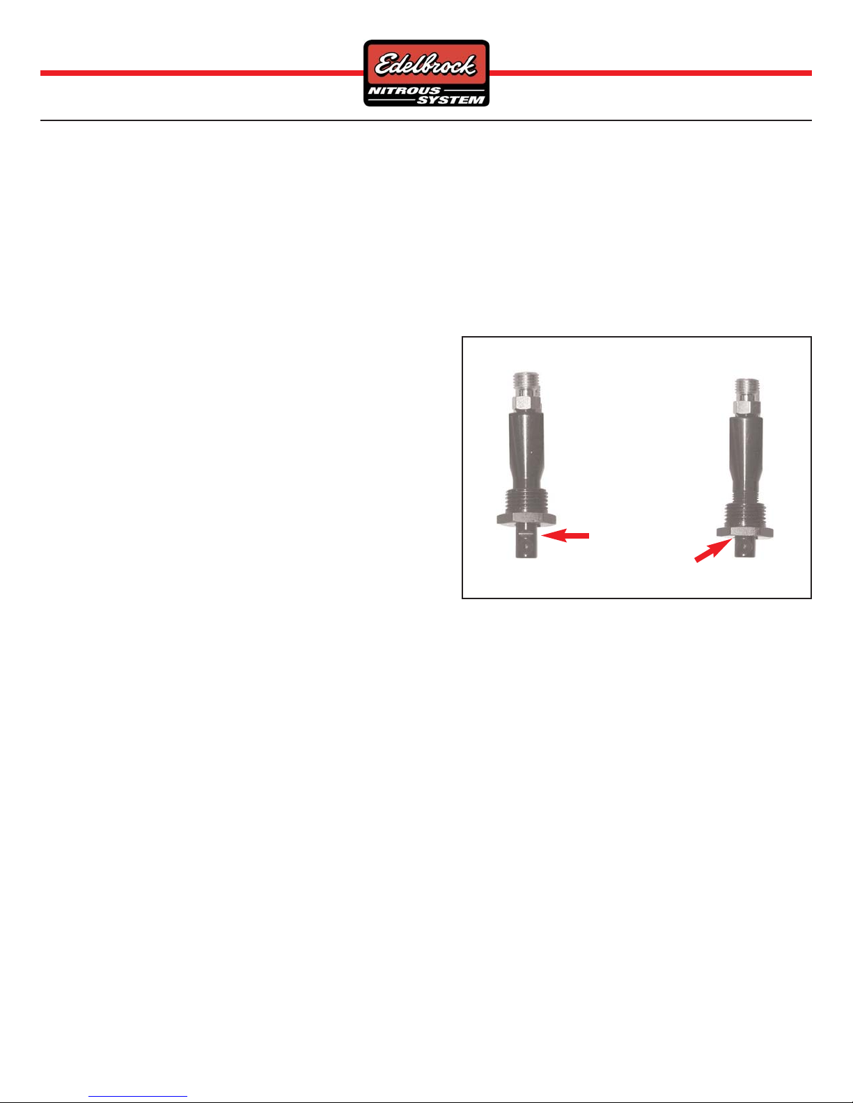
Bottle placement is critical to the
performance of your nitrous system. It is
important to understand how the bottle
valve and siphon tube are assembled to
properly orient the bottle in your vehicle
and ensure that it picks up liquid nitrous
while undergoing acceleration. All nitrous bottles are assembled so that the bottom of the siphon
tube is at the bottle of the bottle, opposite the bottle label (as pictured above).
An Edelbrock nitrous bottle cannot be mounted upside-down. Edelbrock does not offer a
non-siphon tube bottle for automotive use. If the bottle must be mounted parallel to the
axles of the vehicle (sideways), the label must be angled at approximately 45° towards the
rear and pointing to the lower rear-facing quadrant of the bottle. All of this positioning information is critical to system
operation. It is most important to draw as much liquid nitrous as possible. The siphon tube cannot do this unless positioned
correctly.
2.3 Nitrous Bottle Installation
After you have determined the location and orientation of the nitrous bottle, use the following
procedure to install the nitrous bottle:
1. Disconnect the vehicle’s battery.
2. Determine the location of the bottle within the confines of the rear of the vehicle.
3. Once a mounting location has been determined, raise the vehicle (following all safety
practices involved in working on a vehicle from under the vehicle) and verify that there are
no fuel lines, fuel tank(s), brake lines, emissions equipment, or structural members in the
way of potential mounting bolt locations.
4. Install the rubber insulators within the bottle brackets.
5. Install the bottle in the bottle brackets.
6. Using the mounting bracket bolt holes as templates, mark an area for each of the brackets
with chalk, scribe, or marking pen to locate the bottle placements for drilling.
7. Drill two 3/8” mounting holes for each bracket making absolutely sure that you are not
drilling into anything dangerous or critical to the safety of the vehicle.
8. If a bottle heater blanket is going to be used, be sure that brackets are installed 8½” apart
from each other.
9. Install the bottle mounting brackets using “Grade 8” bolts, nuts and flat washers (not
included with the kit). Use fender washers underneath the vechile for sheet metal mounting.
10. Tighten the mounting bolts using a thread locking compound.
Optional Blowdown Tube (PN 72960) Installation
11. If you are using a safety blowdown tube, mock this up on the bottle to decide where the tube
will go through the floor.
12. Mark the floor where the tube will go and using a ½” drill bit, drill through the floor on the mark.
13. Install the Safety Tube on the bottle and cut off any excess tube so that only 1”to 2” are protruding through the vehicle.
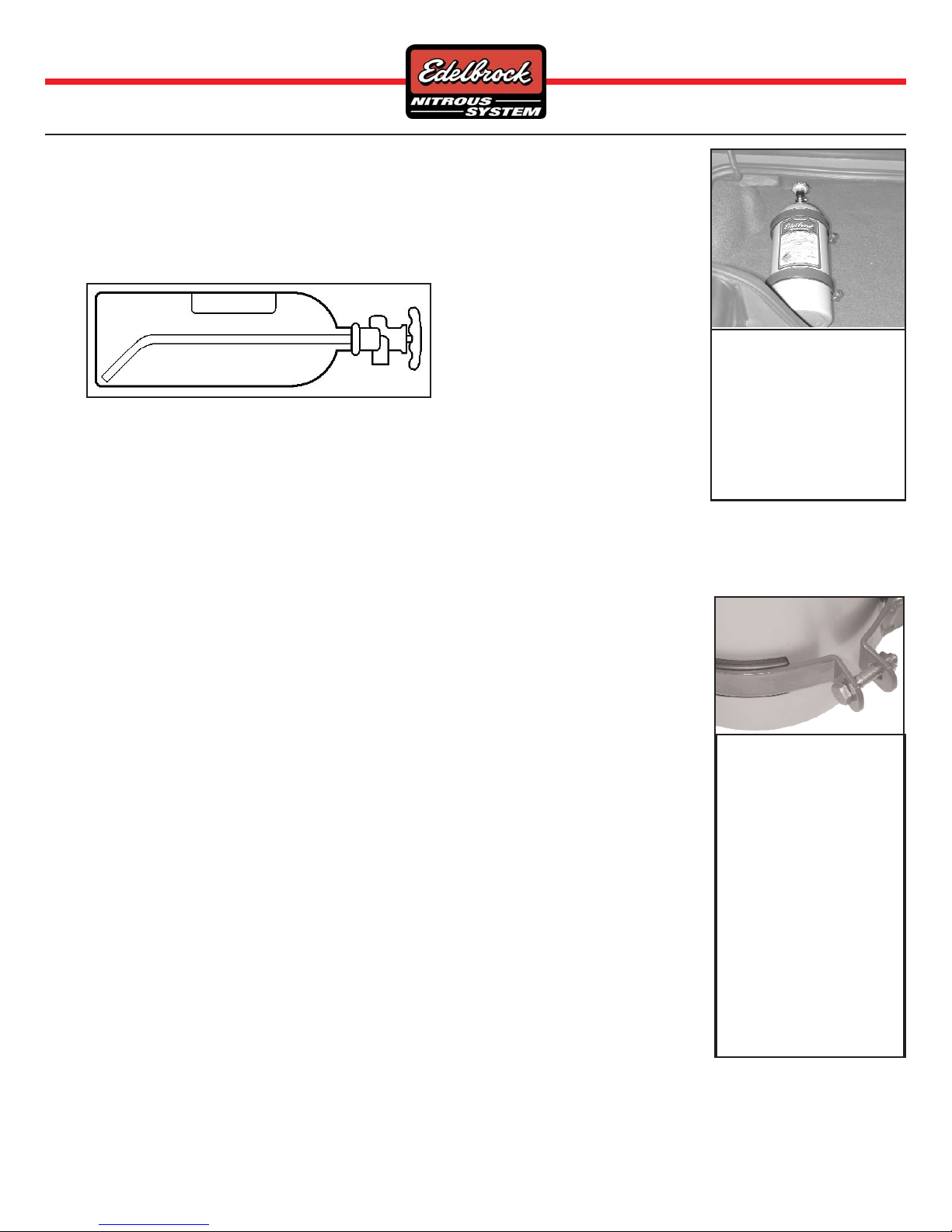
The most efficient mounting
method is the lay-down
position with the valve handle
towards the front of the
vehicle. This position allows
the greatest amount of liquid to
be used before the siphon tube
begins to pick up gaseous
nitrous oxide.
Shown here is a bottle with
a bottle bracket properly
installed with the rubber
insulator. The distance
between the bottle brackets
is somewhat adjustable.
Remember, mount the short
bottle bracket at least 1”
from the bottom of the
bottle, and never cover any
of the bottle labels with the
bottle bracket.
Do not attempt to install the
bottle in the bracket
without the rubber
insulator.

WWW.EDELBROCK.COM
©2007 Edelbrock Corporation
Brochure #63-70216 Page 8 of 16
Catalog #70216
Rev. 5/07 - DC/mc
2.4 Nitrous Feed Line Mounting
1. Determine the route your main nitrous feed line will follow. Ensure that the path does not route the nitrous feed line too
close to the exhaust system, suspension, electrical lines/components or tires.
2. Attach nitrous supply line to bottle.
3. Feed nitrous line along proposed route.
4. Secure the nitrous supply line to the underside of the vehicle.
NOTE: The stainless steel covering of the main nitrous feed line is very abrasive. Shield painted components or sensitive
system components like electrical, fuel lines, brake lines or suspension components to prevent them from contacting the
main feed line. Rubber hose can be slid over and retained as a chafe guard if necessary.
5. Leave the nitrous line end under the hood loose pending installation of the nitrous solenoid.
2.5 Edelbrock E1 Nitrous Nozzle Installation
1. Thread the E1 nozzle into the mounting collar to be sure that
both the nitrous and fuel outlets are fully visible when
threaded in, such as shown in the picture to the right. If the
fuel outlet, which is most succeptable to being blocked is
blocked, serious engine damage will most likely occur. If the
nozzle does not seat deep enough into the collar you may
need to run a tap through the hole to clean out and deepen
the threads.
2. Disconnect the intake air temperature sensor from the
intake boot and remove the intake boot (leading from the air
filter housing to the throttle body).
3. Find a location on the intake boot that has ample clearance
to install the nozzle and a clean shot at spraying through the
throttle body into the engine. We mounted the nozzle in the bottom of the boot just before the throttle body. Also make sure
that you have clearance for the nozzle with the nitrous and fuel lines connected.
4. Drill a hole in the intake boot where you will be installing the nozzle using a 9/16” drill bit.
5. Install the nozzle mounting collar in the boot with the nut on the outside of the boot. Put a small amount of lock-tite on the
collar nut to ensure that the collar and nut do not come loose in the intake tract.
6. Install the E1 nozzle into the nozzle collar using Teflon paste. Be sure that the nozzle outlet is clocked so that it sprays
through the throttle body and into the engine.
7. Re-install the intake boot.
2.6 Solenoid Assembly and Installation
Nitrous Solenoid Assembly
1. Hold the nitrous solenoid securely in a bench vise, being careful not to harm the solenoid or block the inlet or outlet ports
of the solenoid.
2. Install the nitrous filter fitting (4AN x 1/8”NPT Blue Fitting) into the inlet port of the nitrous solenoid using Teflon Paste.
3. Install the nitrous outlet fitting (3an x 1/8”NPT Blue Fitting) into the outlet port of the nitrous solenoid using Teflon Paste.
4. Remove the solenoid from the vise and attach a solenoid bracket using the supplied solenoid screws.
5. Find a location in the engine compartment to mount the solenoids, making sure that it is within reach of the feed line and
E1 nozzle.
6. Connect the straight end of the 3AN x 15” 90° blue hose to the outlet port of the nitrous solenoid.
7. Select the nitrous jet you will be using from the jet map on page 4 and place this in the “N” port of the E1 nozzle. Connect
the 90° end of the 3AN line to the nozzle with the jet installed.
8. Connect the 4AN nitrous feed line to the inlet port of the nitrous solenoid.
Correct Nozzle Depth
into Collet
Incorrect Nozzle
Depth into Collet
Fuel Outlet Blocked
Fuel Outlet Fully
Exposed Correctly

WWW.EDELBROCK.COM
©2007 Edelbrock Corporation
Brochure #63-70216 Page 9 of 16
Catalog #70216
Rev. 5/07 - DC/mc
2.6 Solenoid Assembly and Installation (Continued)
Fuel Solenoid Assembly
1. Hold the fuel solenoid securely in a bench vise, being careful not to harm the solenoid or block the inlet or outlet ports of
the solenoid.
2. Install the fuel inlet fitting (4AN x 1/8”NPT Red Fitting) into the inlet port of the fuel solenoid using Teflon Paste.
3. Install the fuel outlet fitting (3AN x 1/8”NPT Red Fitting) into the outlet port of the fuel solenoid using Teflon Paste.
4. Remove the solenoid from the vise and attach the remaining solenoid bracket using the supplied solenoid screws.
5. Again, find a location in the engine compartment to mount the solenoid, making sure that it is within reach of the fuel feed
line and E1 nozzle.
6. Select the corresponding fuel jet from page 4 and place in the ‘F’ port of the E1 nozzle. Connect the 3AN x 15” 90° red fuel
line from the outlet fitting of the fuel solenoid to the fitting on the E1 nozzle with the jet installed.
2.7 Fuel Line Installation
Follow the Dodge Charger fuel line installation instructions supplied with the fuel line.
1. Install the 4AN x 1/8”NPT red fitting into the 6AN Fuel Pressure Take-Off Adapter using Teflon Paste.
2. Where the fuel line connects to the Fuel Line Fitting ‘B’, install the supplied 6AN Fuel Pressure Take-Off Assembly between
the line and the fitting.
3. Install the 3ft. 4AN Red Line from the fitting just installed on the fuel line to the inlet of the Performer Fuel Solenoid.
4. Turn the ignition key to the ‘On’ position, but do not start the vehicle. Check the fuel lines for any leaks. If leaks are present,
fix the leak immediately.
5. With the key in the ‘On’ position, but the engine not running, purge fuel through the fuel line to the Performer Fuel Solenoid
inlet by carefully loosening the line at the inlet fitting until fuel begins to leak out. This ensures that the first time the nitrous
system is used it has adequate fuel supply for the nitrous. If you do not do this step your first use of the nitrous will be
extremely lean because the fuel side of the system is still trying to get fuel into the nozzle and air out of the lines.

WWW.EDELBROCK.COM
©2007 Edelbrock Corporation
Brochure #63-70216 Page 10 of 16
Catalog #70216
Rev. 5/07 - DC/mc
3.0 Electrical System Installation
3.1 Nitrous Electrical Components Bill of Material (BOM)
12-4
5
6
789
10
11 12 13 14
Item Qty. Description
❑1 1 Wide Open Throttle Module
❑2 1 6ft. 16 AWG Wire (Blue)
❑3 1 6ft. 16 AWG Wire (Yellow)
❑4 1 6ft. 16 AWG Wire (Black)
❑5 2 18/22 AWG Female Spade Connector, Nylon Insulated
❑6 1 6ft. 16 AWG Wire Assembly, Fused, In-Line (Red)
❑7 3 Splice, Insulated Displacement (16/18 AWG)
❑8 1 15 AMP ATO Blade Fuse
❑9 1 On/Off Round Rocker Switch
❑10 4 16/22 AWG Insulated Butt Connectors
❑11 4 18/22 AWG Male Spade Connector, Nylon Insulated
❑12 2 14/16 AWG Male Spade Connector, Nylon Insulated
❑13 2 14/16 AWG Female Spade Connector, Nylon Insulated
❑14 4 18/22 AWG Female Spade Connector, Nylon Insulated
Important: The wiring hardware and instructions included with this kit are intended for a 12-volt electrical system only. Before
attempting to wire your Edelbrock Performer Nitrous Oxide System, examine and follow the wiring diagram on the following page. Please
call the Edelbrock Technical Department at (800)416-8628 with any questions concerning electrical wiring.

WWW.EDELBROCK.COM
©2007 Edelbrock Corporation
Brochure #63-70216 Page 11 of 16
Catalog #70216
Rev. 5/07 - DC/mc
3.2 Wide Open Throttle Module Wiring Diagram
3.3 Nitrous Electrical System Installation Procedure
Determine a location for the wIde open throttle relay and fuse holder wire. Most common installations locate these components
close to the battery. However, these connectors are water resistant, not waterproof, so care is required when mounting this
assembly under the hood of your vehicle.
Wire Schematic Origin and Destination Map
Wire Color System Origin Destination Terminal Used
Red Main System Power WOT Module Battery +12V Signal Ring
Yellow Solenoid Power WOT Module Solenoid Spade
Blue TPS 5 Volt Input WOT Module Arming Switch Spade
Blue TPS 5 Volt Input Arming Switch TPS Sensor Splice Connector
Black Wide Open Throttle Module WOT Module Chassis Ground Ring
Black Solenoid Ground Solenoid Chassis Ground Ring
Black Solenoid Power In Solenoid WOT Module Spade
Br/Or TPS 5 Volt Reference Throttle Body ECM Harness -
3.4 Wide Open Throttle (WOT) Module Installation
The WOT module includes 3 feet of color-coded wires and terminals to make the electrical system installation for your Edelbrock
Nitrous System as easy as possible. We recommend that you do not cut any lengths of wires from the wire harness or complete
the wiring of the system until all of the mechanical components are securely mounted in their permanent locations.
Once all the solenoids and switches are placed, route the un-cut wires from the harness to each location allowing enough wire
length on each circuit to not interfere with operating linkages, heat sources, brackets, etc. Pay particular attention to sharp edges
along the route of your wire harness as they can chafe the wire and cause your system to fail.
Once you have decided the location of the “WOT” module secure it with fasteners (not included with kit) such as sheet metal
screws, bolts & nuts, etc. Allow for some slack in the red wire that connects the “WOT” moduel and fuse holders together.
Battery Ground
Fuse
w/Holder
Red
Black
Blue
Yellow
Nitrous
Solenoid
Fuel
Solenoid
Ground
Ground
Brown/Orange Wire
Black Connector
Located on
Throttle Body
Wide Open Throttle
(WOT) Module

WWW.EDELBROCK.COM
©2007 Edelbrock Corporation
Brochure #63-70216 Page 12 of 16
Catalog #70216
Rev. 5/07 - DC/mc
3.5 Wiring
1. Verify that the battery is disconnected. If it is not, remove the ground strap and place it away from the battery to keep it from
shorting out.
2. Locate the red wire with fuse holder and affix it to the red wire on the “WOT” module with the provided butt connector or you
can solder the two ends and then heat shrink, if so desired (required soldering iron, rosin core solder and heat shrink not
provided in kit).
Note: You may need to cut the red wire coming out of the WOT module wiring harness to accommodate the mounting location
and proximity to the battery.
3. Connect the red wire with fuse holder to the positive terminal of the car battery.
4. Locate the black wire on the WOT harness. Affix the black wire with ring terminal to a good chassis ground. We recommend
using an existing ground used by the OEM.
5. Locate the yellow wire on the WOT haness. Using provided male and female spade connectors, attach the yellow wire to one
black wire from each of your solenoids.
6. Locate the remaining black wire on each of the solenoids. Using provided ring terminal, affix the black wires to a good chassis
ground.
See step 4.
7. Locate the blue wire on the WOT module. With provided female spade connector, attach blue wire to one of the terminals of
the on/off rocker switch.
8. Attach the blue wire extension to the free terminal of the on/off toggle switch.
9. Locate the brown/orange wire running out of the TPS/Throttle Body connector on the vehicle. This connector is located on
the throttle body and has 6 wires coming out of it. This is connected to terminal #1 of the connector.
10. Affix blue wire from the on/off rocker switch to the brown/orange wire from the throttle position sensor with provided splice
connector.
3.6 Arming Switch Installation
The arming switch is a black, non-illuminated switch that is a “Master” arming switch for your nitrous system. Without it, your
nitrous system would be “on” all of the time and capable of engaging anytime you go to wide-open throttle conditions with your
vehicle. The switch is marked to indicate when it is in the “on” or “off” position. Therefore, it should be placed in an obvious
location well within the line of sight and easy reach of the driver. Please refer to the procedures below for the installation of the
arming switch:
1. Locate the final position of your arming switch.
2. Using a uni-bit or 13/16” drill bit, drill a hole for the switch location.
Note: If using a uni-bit, try to drill the hole slightly under 13/16” diameter for a snug fit.
3. Insert the switch from infront of the mounting hole, it should lock in place.
4. Do not wire until all other mechanical components are in place. Please see the electrical system installation instructions for
further imformation.
3.7 Final Solenoid and WOT Module Installation Recommendations
At this time, it is advised that you double-check the following areas:
1. Double Check all wires making sure they do not come in contact with any heat sources like exhaust manifolds, EGR
crossover, etc.
2. Check all connections for exposed wire, try to keep all wire within the insulation or use shrink wrap to prevent any loose
wires from shorting out.

WWW.EDELBROCK.COM
©2007 Edelbrock Corporation
Brochure #63-70216 Page 13 of 16
Catalog #70216
Rev. 5/07 - DC/mc
4.0 Before You Run Your Vehicle Using Your Edelbrock Nitrous System
You have just completed the installation of your Edelbrock Nitrous System. It is time to perform some basic system checks to
ensure all of the work you have done is correct and ready to operate properly. The following procedure is designed to validate the
operation of your nitrous system before operating your vehicle:
Note: Before performing steps 1 through 4, make sure that the nitrous bottle is closed and main nitrous supply line
is empty of any nitrous.
4.1 Fuel System Check
1. Hook up all battery leads.
2. Double-Check all wires and leads for signs of heat and proper connections.
3. Start your vehicle.
4. Check all fittings for leaks. Pay close attention to the fuel line fittings making certain that they are all dry.
4.2 Nitrous System Check
1. With the vehicle’s engine running, slowly open the nitrous bottle valve.
Note: There should be no change in engine idle speed. If idle speed changes, close nitrous bottle valve immediately
and refer to the “Troubleshooting Guide” section.
2. Inspect nitrous lines and fittings for leaks using a soapy water mixture and a small brush.
3. If any of the fittings/connections show bubbling around the attachment nut or on the threaded area of the fitting, shut
the nitrous bottle valve off immediately and dry the fitting before attempting any service to that particular fitting
connection.
4. If the engine idle does not come up, and all of the fittings appear to be leak-free, you have successfully completed
the installation of your Edelbrock Nitrous System.
5.o Solenoid Inspection and Maintenance
1. Close valve on nitrous bottle.
2. Make sure all nitrous supply lines are free of pressure before removal of any system solenoid.
a. Empty main nitrous supply line at the nitrous bottle. Take care to not breathe or expose your skin to nitrous.
b. Do not open pressurized fuel lines over a hot engine.
3. Remove nitrous solenoid from the engine and securely clamp it into a vise, taking great care not to damage the solenoid.
4. Remove the solenoid cover retaining nut from the top of the nitrous solenoids.
5. Remove the coil and housing from the nitrous solenoid base.
6. Unscrew the stem from the nitrous solenoid base. Do this by using a solenoid stem removal tool or by “double nutting” the
stem and unscrewing the stem from the housing body. Do not use pliers on solenoid stem! Damage to the stem will
result.
7. Carefully remove the stem, spring and plunger from the solenoid base paying close attention to the way they are assembled.
8. Examine the plunger seal for swelling, cuts and abrasions. The seal surface should be flat, except for a small circular
indentation in the center of the seal.
A seal that has been contaminated or over-pressurized will bulge from exposure to chemicals other than nitrous oxide. It
can appear to extend down from the plunger and be dome-shaped. A contaminated seal may return to its original shape if
left out in fresh air for approximately 48 hours. It may then be returned to sevice. If it does not return to its original shape,
it must be replaced.
9.
Clean the solenoid body. Do not use an oil-based solvent to clean any part of the solenoid. Use paint thinner or
electrical contact cleaner. Remove any contaminants that may be present. Make sure solenoid body is clean, dry and free
of oils before assembly.
10. Replace the O-Ring, plunger and piston spring.
11. Re-assemble the solenoid by reversing disassembly procedure.

WWW.EDELBROCK.COM
©2007 Edelbrock Corporation
Brochure #63-70216 Page 14 of 16
Catalog #70216
Rev. 5/07 - DC/mc
6.0 Troubleshooting Your Edelbrock Nitrous System
How to use our Troubleshooting Flowchart:
The troubleshooting of a nitrous system is basic and straight forward. The symptom chart is divided by symptom, cause and action
required. Determine your problem (symptom), identify the potential problem (cause), and correct the problem (action required).
Symptom #1 -- There is no change in engine speed when the system is activated.
1. Double check to see that the system is wired correctly.
a. Compare wiring to schematic.
i. Wire per instructions. See “
Wide Open Throttle Wiring Diagram
” section.
2. Restricted fuel line.
a. Inspect fuel line for restrictions.
i. Remove restrictions (kinks in rubber line, pieces of rubber hanging in flow path, etc.)
b. Check fuel pressure.
i. Without the nitrous system armed, the factory fuel pressure should be around 38-45psi. See your dealership.
Symptom #2 -- Change in engine speed when nitrous bottle valve is opened.
1. Malfunctioning nitrous solenoid.
a. Repair/Replace solenoid. See “
Solenoid Inspection and Maintenance
” section.
2. Contamination in nitrous solenoid.
a. Remove and inspect the solenoid for dirt around the seat area of the plunger in the solenoid.
Symptom #3 -- Engine runs excessively rich when system is activated.
1. Nitrous bottle valve not fully opened.
a. Check bottle valve.
i. Open valve fully.
2. Nitrous bottle mounted improperly.
a. Mount bottle properly. See “
Nitrous Bottle Installation
” section.
3. Plugged nitrous filter.
a. Clean and/or replace the nitrous filter.
b. See nitrous solenoid symptom #2.
4. Low bottle pressure.
a. Weigh bottle.
i. Bottle should be 10lb. above empty bottle weight listed on bottle label when full. (15lb. will be more).
b. Check bottle pressure.
i. Maintain 80°-85° of bottle surface temperature.
5. Check for correct jetting.
Symptom #4 -- High RPM misfire when system is activated.
1. Excessive spark plug gap.
a. Inspect spark plugs.
i. Set plug gap per manufacturer’s specification.
ii. Contact the manufacturer of your plugs for more information.
2. Weak ignition/ignition component failure.
a. Inspect ignition components.
i. Replace worn components.
ii. Upgrade ignition system to high performance high load capable ignition components.

WWW.EDELBROCK.COM
©2007 Edelbrock Corporation
Brochure #63-70216 Page 15 of 16
Catalog #70216
Rev. 5/07 - DC/mc
Symptom #5 -- Engine detonates heavily when system is activated.
Inadequate fuel delivery due to:
1. Plugged fuel filter.
a. Inspect fuel filter.
i. Clean or replace filter.
2. Crimped fuel line.
a. Inspect fuel line.
i. Replace crimped line.
3. Weak or inadequate fuel pump.
a. Install fuel pressure gauge. Run engine under load at wide open throttle, with system activated and monitor the fuel
pressure. If the fuel pressure drops significantly the stock pump may be worn or inadequate.
i. Repair or replace fuel pump.
ii. Install nitrous dedicated fuel supply.
4. MAKE SURE THERE IS NOT A NON-NITROUS COMPATIBLE AFTERMARKET CHIP OR PROGRAMMING IN THE ECM!
Symptom #6 -- No change in performance when system is activated.
1. System wired incorrectly.
a. Compare wiring to schematic.
i. Wire per instructions.
2. Loose ground wires.
a. Connect test light to battery “+” (positive) terminal. Check for continuity at grounds.
i. Tighten/repair loose grounds.
3. No power to arming switch.
a. With ignition on, connect test light to battery “-” (negative) terminal. Check for power at pole #1 on arming switch.
i. Repair wiring.
4. Malfunctioning arming switch.
a. With ignition on, turn arming switch on. Connect test light to battery “-” (negative) terminal. Check for power at red
wire on arming switch.
i. Replace arming switch.
5. WOT switch may not be set to proper voltage.
a. Attach a test light to the power output (Yellow wire) of the WOT switch and check
for power at wide open throttle.
i. Adjust the pot voltage setting to correct voltage. The adjustable pot screw
relocated inside the WOT switch as pictured to the right.
6. Inadequate nitrous supply.
a. Weigh bottle.
i. Bottle should be 10 lbs. above empty bottle weight listed on bottle label
when full.
b. Check bottle temperature.
i. Maintain 80°-85°F of bottle surface temperature.
c. Check bottle valve.
i. Open valve fully.
d. Check bottle orientation.
i. Mount bottle properly.
7. Mismatch nitrous/fuel jetting.
a. Compare jetting to recommended values.
i. Install correct jets.
b. Verify the number stamped in the jet match the desired power level.
i. Acquire the right size jets and install the correct jets.
Adjustment screw for the WOT
voltage setting.

WWW.EDELBROCK.COM
©2007 Edelbrock Corporation
Brochure #63-70216 Page 16 of 16
Catalog #70216
Rev. 5/07 - DC/mc
Symptom #6 -- No change in performance when system is activated
(Continuation)
8. Excessive fuel pressure.
a. Perform fuel pressure test procedure.
b. Install fuel pressure gauge.
i. Regulate pressure to proper settings.
9. Loose nitrous solenoid wiring.
a. Inspect solenoid wiring. See “
Electrical System Installation
” section.
b. Consult a book concerning proper wiring methods.
10. Malfunctioning nitrous or fuel solenoids.
a. Inspect solenoid wiring. See “
Electrical System Installation
” section.
i. Repair wiring.
b. Inspect solenoids. See symptom #2.
i. Rebuild/replace solenoid.
Symptom #7 -- Engine detonates mildly when system is activated.
1. Inadequate octane fuel.
a. Verify what gasoline your using.
i. Use a higher octane fuel.
2. Spark plug heat range too high.
a. Verify what heat range the plug is and how it functions in a high-load, high-performance application.
i. Install a performance spark plug.
ii. Reduce spark plug heat range.
3. Too much nitrous flow.
a. Verify the size of the nitrous jet.
i. Install the proper nitrous jet.
b. Check bottle temperature and pressure.
i. Ensure before every nitrous usage that you only use nitrous when the temperature and pressure of your bottle
are correct.
4. MAKE SURE THERE IS NOT A NON-NITROUS COMPATIBLE AFTERMARKET CHIP OR PROGRAMMING IN THE ECM.
Symptom #8 -- Vehicle surges under acceleration when system is activated.
1. Inadequate nitrous supply.
a. Weigh bottle.
i. Bottle should be 10lb. above empty bottle weight listed on bottle label when full. (15lb. will be more).
b. Check bottle pressure.
i. Maintain 80°-85° of bottle surface temperature.
c. Check bottle valve.
i. Open valve fully.
d. Check bottle orientation.
i. Mount bottle properly.
Edelbrock Corporation, 2700 California Street, Torrance, CA 90503
Tech Line: (800) 416-8628
E-mail: [email protected]
Table of contents
Other Edelbrock Other manuals
Popular Other manuals by other brands

Varec
Varec 2920 Installation and operation manual

Elenco Electronics
Elenco Electronics 21-130 Specifications

Thomas
Thomas SAF-T-LINER C2 manual

Boumatic
Boumatic Xcalibur Operator's manual

Schacht
Schacht WOLF FL3051 Assembly instructions

UniData Communication Systems
UniData Communication Systems Neon 3016A manual