OVE SIERRA 60 User manual

1OVE 2015-05-27 2800 Etienne Lenoir, Laval
Québec H7R 0A3 Canada
Purchase date: _________________________ Product Tracking Reference: ________________________
Questions, problems, missing parts?
Before returning to your retailer, call our customer service department at
1-866-839-2888, 9 a.m. - 5 p.m., EST, Monday - Friday
SIERRA 60 TUB DOOR

2
TABLE OF CONTENT
PACKAGE CONTENT.......................................................................................................................................... 4
HARDWARE CONTENT...................................................................................................................................... 5
TOOLS REQUIRED............................................................................................................................................. 5
SAFETY INFORMATION..................................................................................................................................... 6
PREPARATION.................................................................................................................................................... 6
SHOWER REVERSIBILITY.................................................................................................................................. 7
WALL TO WALL MEASURES............................................................................................................................. 7
WALL TRACK INSTALLATION........................................................................................................................... 8
FIXED PANEL INSTALLATION.......................................................................................................................... 9
SUPPORT BAR INSTALLATION....................................................................................................................... 10
DOOR PANEL INSTALLATION......................................................................................................................... 12
HANDLE INSTALLATION & SEALING.............................................................................................................. 14
CARE AND MAINTENANCE............................................................................................................................. 15
LIMITED 5 YEARS WARRANTY........................................................................................................................ 15

3
PACKAGE CONTENT
B
DE
F
H
I
R
M
T
U
Q
O
N
G
C
J
P
K
V

4
PACKAGE CONTENT
PART# DESCRIPTION QTY CODE
BAluminum track 199STR3612-WM
CFixed glass panel 199SGC10053-WM
DSupport bar’s anchors 299SGC1011-WM
ERoller stoppers 299SDS0002-WM
FSupport bar 199SGS1027-WM
GFixed panel’s brackets 299SGC0041-WM
HTop door rollers 299SWE0024-WM
IAnti-jump pegs 299SWE0025-WM
JDoor panel 199SGD0038-WM
KGlass panels vertical seal strips (short) 299SRU0140
MDoor handle 199SHA1027-WM
NFixed panel’s bottom seal strip 199SRU0141
ODoor panel’s bottom seal strip 199SRU0142
PGlass panels vertical seal strips (long) 299SRU0143
QSliding door guide (with its rubber tting) 199SGC0042-WM
RDoor vertical seal strip 199SRU0144
TDecorative end caps 299SHW0049-WM
UDecorative metal track 199STR1050-WM
VAluminium prole 199STR1044-WM
WHardware content 199SHW0073-WM

5
HARDWARE CONTENT
TOOLS REQUIRED
Pencil Screwdriver Level
Measuring Tape Silicone Rubber mallet Cutter
Safety glasses
Allen key
2.5mm & 5mm Ratchet
5mm Bit socket
Drill with ceramic tile bits
ø3mm (1/8”) & ø4mm (3/16”) & ø8mm (5/16”)
FFEE
DD
BB
Wall Anchor
ø8x30mm
7+2
Screw
ST5x30mm
3+1
Cap
3x
Fitting
3x
GG
ABS Cap
4x
Screw
ST4x12mm
3+1
HH
CC
Screw
ST4x20mm
2+1
AA
Screw
ST5x35mm
4+1

6
Please read and understand this entire manual before attempting to assemble, operate
or install the product.
WARNING
• Distributor is not responsible for any damage to the unit or personal property caused
by improper installation. If you disregard instructional warnings, you will void your
warranty and possibly deal with water damage.
CAUTION
• Carefully remove product from packaging and keep packaging until installation is
complete.
• Inspect all parts for damage; if there is damage to the unit prior to installation,
please contact customer service at the number provided in this guide.
• Install the shower on a oor that is level and able to accommodate the weight of the
unit and an occupant.
• Please, consult local building codes and compliance standards prior to installation
and ensure conformity.
SAFETY INFORMATION
PREPARATION
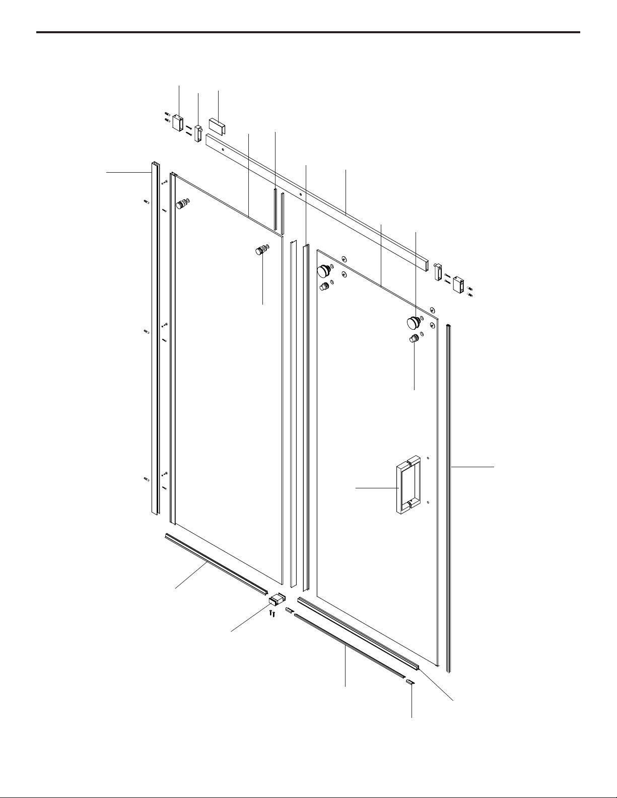
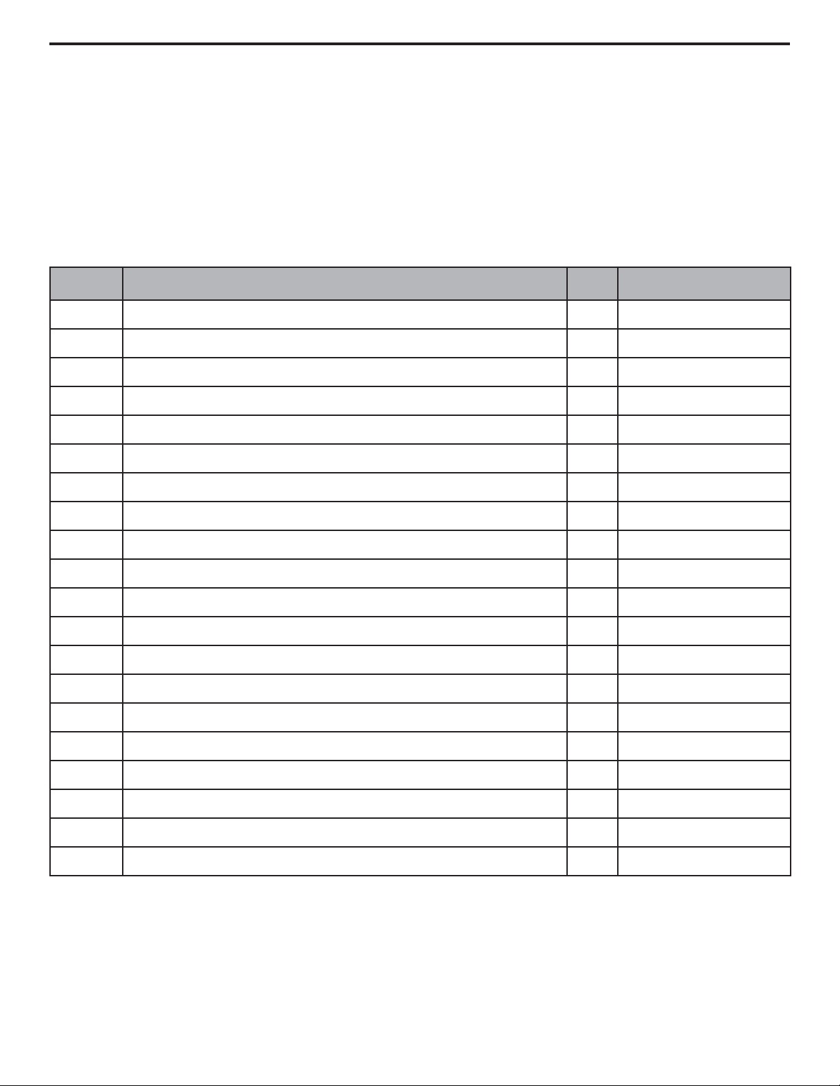
Before beginning assembly of product, make sure all parts are present. Compare
parts with package contents list and hardware contents list. If any part is missing or
damaged, do not attempt to assemble the product.
Estimated Assembly Time: Shower (60 min).
Handle the tempered glass with caution! Improperly handling the glass can
cause it to break suddenly in small pieces (never in pointed fragments).
Dot NOT put glass panels on hard surfaces, always work on clean and soft
surface (e.g. towel). Shattering may occur otherwise!
HEAVY PRODUCT! You will need at least two people to install this
unit properly.

7
• This instruction is drawn up for an opening from right to left (see illustration B).
• For an installation from left to right (see illustration A), use the same instructions, but switch around the
panels: mirror effect.
SHOWER REVERSIBILITY
A B
WALL TO WALL MEASURES
• Measure the thickness of your tiles on either side before installing the metal tracks. A thicker tile will limit
your space to install the shower panels.
• Make sure to have a tile to tile distance (D) between 1478mm (58 3/16 in) min. and 1493mm (58 3/4 in)
max. (see image).
Make sure to have a distance (D) from the left side tile
to the right side tile:
D Min: 1478mm (58 3/16 in)
D Max: 1493mm (58 3/4 in)
If D < 1478mm (58 3/16 in) you can cut the support
bar to adequate size. Only cut the side with no holes!

8
1. Place the track (B) at approximately 3/4 in. (20 mm) from the edge of the tub to the track center.
2. Mark the position of the track (B).
3. Drill the holes according to the illustration.
4. Install the track (B) on the wall using wall anchors (AA) and screws (BB).
WALL TRACK INSTALLATION
20mm
Φ 8mm
AA
BB
B
1
3
2
4
B

9
1-2. Cut the xed panel’s bottom seal strip (N) to size and attach the strip (N) on the xed glass panel (C).
3-4. Mark the position of sliding door guide (Q) and drill the hole.
5. Install the sliding door guide (Q) using the screws (CC).
6-7. Place the xed glass panel (C) in the sliding door guide (Q) and the track (B).
Note: The wall track (B) allows you to adjust the position of the xed glass panel (C). Adjusting the
depth and/or giving the xed glass panel a slight angle allows for precise alignment with the door.
8. Using a 3mm drill bit, drill pilot holes at the top, the center and the bottom of the rail (B).
9. Secure the xed glass panel (C) using screws (DD) and cap (EE) & tting (FF).
FIXED PANEL INSTALLATION
Helpful Hint
Add a drop of
silicone in the
holes before
inserting the
screws
40mm
N
N
C
20mm
714mm
Q
3
Φ4mm
4
CC
5
EE
DD
FF
1
Q
B
C
20mm
C
N
6
2
9
C
N
Q
78
100mm

10
1-2. Slide the two stoppers (E) on the bar (F), then mount the bar anchors (D) without tightening.
3. Mount the bar (F) on the panel (C). Don’t over tighten the brackets (G) in order to adjust the bar level.
Make sure the glass protection gaskets are in place on either side of the glass panel.
4. Make sure the bar is properly leveled and mark the outline of the anchors (D) on the wall.
5-6. Temporarily remove the assembly bar (F).
SUPPORT BAR INSTALLATION
2.5mm
D
E
F
1
G
C2.5mm
D
D
E
F25
3
D
E
F
6
F
4
F
C
D
D
F
G
C
Table of contents
Languages:
Other OVE Other manuals


