69/17
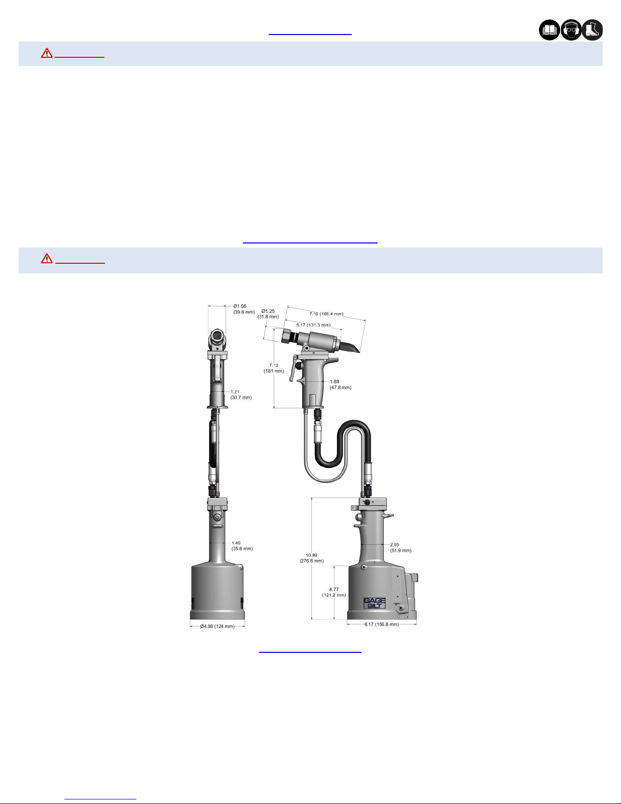
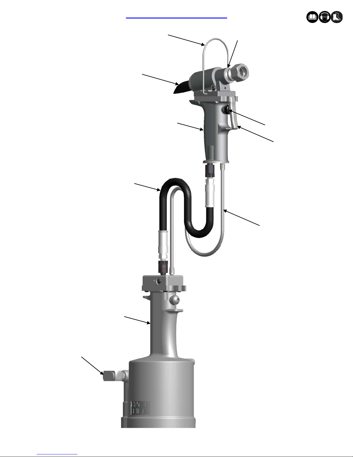
GB751SH-5 INSTALLATION TOOL
SAFETY WARNINGS
GENERAL SAFETY RULES:
1. For multiple hazards, read and understand the safety instructions before installing,
operating, repairing, maintaining, changing accessories on, or working near the
assembly power tool for non-threaded mechanical fasteners.
2. Only qualified and trained operators should install, adjust or use the assembly power
tool for non threaded mechanical fasteners.
3. Do not modify this assembly power tool for non-threaded mechanical fasteners. Modifications can
reduce effectiveness of safety measures and increase the risks to the operator.
4. Do not discard safety instructions; give them to the operator.
5. Do not use assembly power tool for non-threaded mechanical fasteners if it has been damaged.
6. Tools shall be inspected periodically to verify all ratings and markings required are
legible. The employer/user shall contact the manufacturer to obtain replacement
marking labels when necessary.
7. Air under pressure can cause severe injury.
8. Always shut off air supply, drain hose of air pressure and disconnect tool from air
supply when not in use, before changing accessories or when making repairs.
9. Never direct air at yourself or anyone else.
10. Whipping hoses can cause severe injury. Always check for damage or loose hoses and fittings.
11. Cold air shall be directed away from hands.
12. Whenever universal twist couplings (claw couplings) are used, lock pins shall be
installed and whipcheck safety cables shall be used to safeguard against possible
hose-to-tool or hose-to-hose connection failure.
13. Do not exceed the maximum air pressure stated on the tool or manual.
14. Never carry an air tool by the hose.
ADDITIONAL SAFETY RULES FOR PNEUDRAULIC POWER TOOLS:
1. Air under pressure can cause severe injury.
2. Always shut off air supply, drain hose of air pressure and disconnect tool from air
supply when not in use, before changing accessories or when making repairs.
3. Never direct air at yourself or anyone else.
4. Whipping hoses can cause severe injury. Always check for damage or loose hoses and fittings.
5. Cold air shall be directed away from hands.
6. Whenever universal twist couplings (claw couplings) are used, lock pins shall be
installed and whipcheck safety cables shall be used to safeguard against possible
hose-to-tool or hose-to-hose connection failure.
7. Do not exceed the maximum air pressure stated on the tool or manual.
8. Never carry an air tool by the hose.
PROJECTILE HAZARDS:
1. Disconnect the tool from the energy source when changing inserted tools/nose as-
semblies or accessories.
2. Be aware that failure of the workpiece or accessories, or even the inserted tool/nose
assembly itself can generate high-velocity projectiles.
3. Always wear impact resistant eye protection during operation of the tool. The grade of
protection required should be assessed for each use.
4. The risk to others should also be assessed at this time.
5. Ensure that the workpiece is securely fixed.
6. Check that the means of protection from ejection of fastener and/or stem is in place
and operative (such as the deflector).
7. Forcible ejection of the mandrel from the front of the nose assembly is possible.
OPERATING HAZARDS:
1. Use of tool can expose the operator’s hands to hazards, including crushing, impacts,
cuts, abrasions and heat. Wear suitable gloves to protect hands.
2. Operators and maintenance personnel shall be physically able to handle the bulk,
weight and power of the tool.
3. Hold the tool correctly; be ready to counteract normal or sudden movements and have
both hands available.
4. Maintain a balanced body position and secure footing.
5. Release the start-and-stop device in the case of interruption of energy supply.
6. Use only lubricants recommended by the manufacturer.
7. Avoid unsuitable postures as it is likely for these positions not to allow counteracting
of normal or unexpected movement of the tool.
8. If the tool is fixed to a suspension device, make sure that fixation is secure.
9. Beware of the risk of crushing or pinching if nose equipment is not fitted.
10. Due to the tool weight, it is recommended safety shoes be worn during operation.
11. It is recommended tool be operated not more than 50 out of every 60 minutes, where
prolonged use is expected.
REPETITIVE MOTIONS HAZARDS:
1. When using the tool, the operator can experience discomfort in the hands, arms,
shoulders, neck or other parts of the body.
2. While using the tool, the operator should adopt a comfortable posture while maintain-
ing a secure footing and avoiding awkward or off balanced postures. The operator
should change posture during extended tasks; this can help avoid discomfort and
fatigue.
3. If the operator experiences symptoms such as persistent or recurring discomfort, pain,
throbbing, aching, tingling, numbness, burning sensations or stiffness, these warning
signs should not be ignored. The operator should tell the employer and consult a
qualified health professional.
ACCESSORY HAZARDS:
1. Disconnect tool from energy supply before changing the nose assembly or accessory.
2. Use only sizes and types of accessories recommended by the manufacturer. Do not
use other types or sizes of accessories.
WORKPLACE HAZARDS:
1. Slips, trips and falls are major causes of workplace injury. Be aware of slippery surfac-
es caused by use of tool and also of trip hazards caused by the air line or hydraulic
hose.
2. Proceed with care in unfamiliar surroundings. There could be hidden hazards, such as
electricity or other utility lines.
3. The tool is not intended for use in potentially explosive atmospheres and is not insu-
lated against contact with electrical power.
4. Ensure that there are no electrical cables, gas pipes, etc., which can cause a hazard if
damaged by the tool.
NOISE HAZARDS:
1. Exposure to high noise levels can cause permanent, disabling hearing loss and other
problems, such as tinnitus (ringing, buzzing, whistling or humming in the ears). There-
fore, risk assessment and the implementation of appropriate controls for these haz-
ards are essential.
2. Appropriate controls to reduce the risk may include actions such as damping materials
to prevent workpieces from “ringing”.
3. Use hearing protection in accordance with employer's instructions and as required by
occupational health and safety regulations.
4. Operate and maintain the assembly power tool for non-threaded mechanical fasteners
as recommended in the instruction handbook, to prevent an unnecessary increase in
the noise level.
5. Select, maintain and replace the consumable/inserted tool as recommended in the
instruction handbook, to prevent an unnecessary increase in noise.
6. If the power tool has a silencer, always ensure that it is in place and in good working
order when the power tool is being operated.
VIBRATION HAZARDS:
1. Exposure to vibration can cause disabling damage to the nerves and blood supply of
the hands and arms.
2. Wear warm clothing when working in cold conditions and keep your hands warm and
dry.
3. If you experience numbness, tingling, pain or whitening of the skin in your fingers or
hands, stop using the assembly power tool for non-threaded mechanical fasteners,
tell your employer and consult a physician.
4. Support the weight of the tool in a stand, tensioner or balancer, because a lighter grip
can then be used to support the tool.
TERMS AND SYMBOLS
- Product complies with requirements
- Hearing protection and eye protection
WARNINGS - Must be understood to avoid severe
personal injury.
CAUTIONS - show conditions that will damage equip-
ment and/or structure.
Notes - are reminders of required procedures.
- Read manual prior to using equipment
- Wear safety boots