Edge 540 User manual

MadeinVietnam.
Kit features.
• Ready-made—minimalassembly&finishingrequired.
• Ready-coveredcovering.
• Photo-illustratedstep-by-stepAssemblyManual.
Specifications
Wingspan-------------------------------------66.9in-------------------------------170cm.
Wing area------------------------------------764.6 sq.in-------------------- 49.3 sq.dm.
Approximate flying weight----------------10.4 lbs--------------------------------4.7kg.
Length-----------------------------------------60.4in------------------------------153.3cm.
Recommended engine size------------ .1.2 cu.in-------------------------- 2-stroke.
Radio System required 4 channels with 6 digital 6 kg/cm servos
Flying skill level Intermediate/advanced.
“Graphics and specfications may change without notice”.
ASSEMBLY MANUAL MS: SEA 84
The Edge 540 size 120 (SEA-84) is designed for sport flying and
aerobatic flying only.If you are looking for 3D performance
airplane,please choose our Edge 540 size 61-91 (Sea-54) or Edge 540
size120-160 (SEA-26A&SEA-26B).Thank you for your interested in our
Edge 540 airplane.

EDGE 540. Instruction Manual
2
INTRODUCTION.
Thank you for choosing the EDGE 540 ARTF by SEAGULL MODELS. The EDGE 540 was
designed with the intermediate/advanced sport scale in mind. It is a semi scale airplane which is
easytoflyandquicktoassemble.Theairframeisconventionallybuiltusingbalsa,plywoodtomake
itstrongerthantheaverageARTF,yetthedesignallowstheaeroplanetobekeptlight.Youwillfind
thatmostoftheworkhasbeendoneforyoualready. Themotormounthasbeenfittedandthehinges
are pre-installed . Flying the EDGE 540 is simply a joy.
This instruction manual is designed to help you build a great flying aeroplane. Please read this
manualthoroughlybeforestartingassemblyofyourEDGE540.Usethepartslistingbelowtoidentify
all parts.
WARNING.
Please be aware that this aeroplane is not a toy and if assembled or used incorrectly it
is capable of causing injury to people or property. WHEN YOU FLY THIS AEROPLANE YOU
ASSUME ALL RISK & RESPONSIBILITY.
If you are inexperienced with basic R/C flight we strongly recommend you contact your R/C
supplierandjoinyourlocalR/CModelFlyingClub.R/CModelFlyingClubsofferavarietyoftraining
proceduresdesignedtohelpthe new pilot on his waytosuccessfulR/Cflight.Theywillalsobeable
to advise on any insurance and safety regulations that may apply.
ADDITIONAL ITEMS REQUIRED.
.1.2 cu.in 2-stroke engine
4 - 6 digital 6 kg/cm servos
Glow plug to suit engine
Propeller to suit engine
Protective foam rubber for radio
system
Silicone fuel line
TOOLS & SUPPLIES NEEDED.
Thick cyanoacrylate glue
30 minute epoxy
5 minute epoxy
Hand or electric drill
Assorted drill bits
Modellingknife
Straight edge ruler
2mm ball driver
Phillips head screwdriver
220 grit sandpaper
90° square or builder’s triangle
Wire cutters
Masking tape & T-pins
Thread-lock
Paper towels
PARTS LISTING.
FUSELAGE ASSEMBLY
(1) Fuselage
(1) Canopy hatch
WING ASSEMBLY
(1) Right wing half/ aileron
(1) Left wing half with/ aileron
(1) Aluminium dihedral brace
Tail section assembly
(1) Horizontal stabilizer/ elevator
halves.
(1) Rudder halves.
Some more parts.
HARDWAREPACK
COWLING
Landinggear.....

www.seagullmodels.com
3
1) Carefully remove the aileron from one
of the wing panels. Note the position of the
hinges.
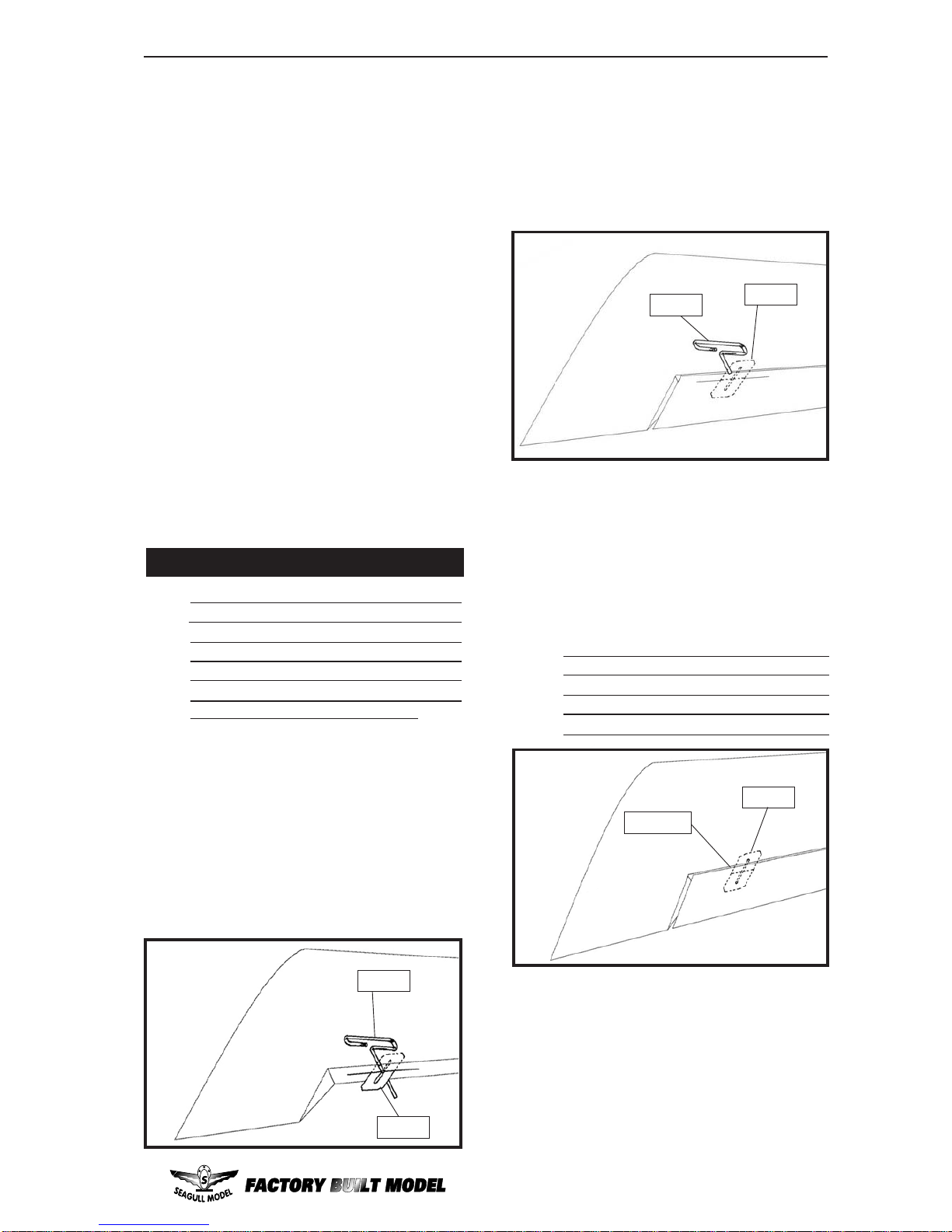
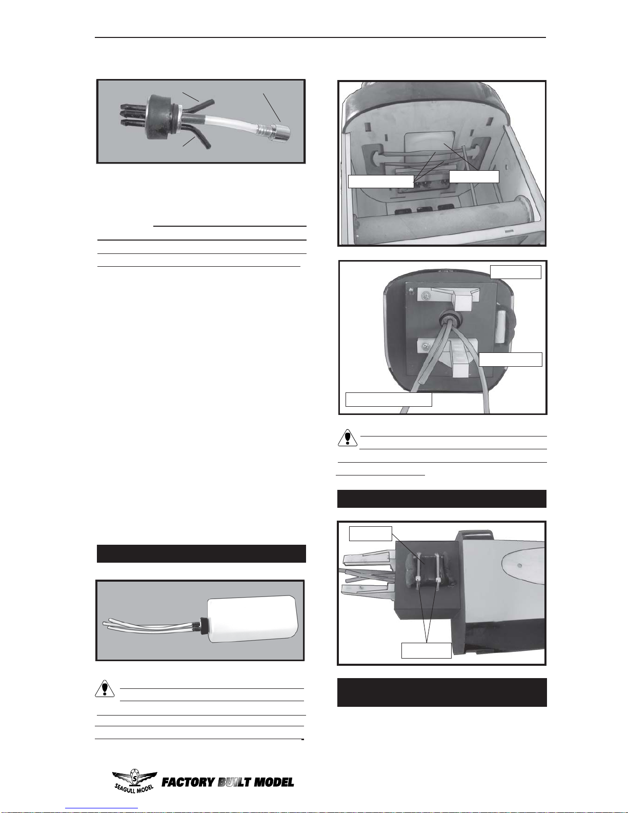
2)Remove each hingefrom thewing panel
and aileron and place a T-pin in the center of
each hinge. Slide each hinge into the wing
panel until the T-pin is snug against the wing
panel. This will help ensure an equal amount
ofhingeisoneither side of the hingelinewhen
the aileron is mounted to the aileron.
3) Slide the wing panel on the aileron until
there is only a slight gap. The hinge is now
centered on the wing panel and aileron.
Remove the T-pins and snug the aileron
against the wing panel.A gap of 1/64” or less
shouldbe maintained betweenthe wing panel
andaileron.
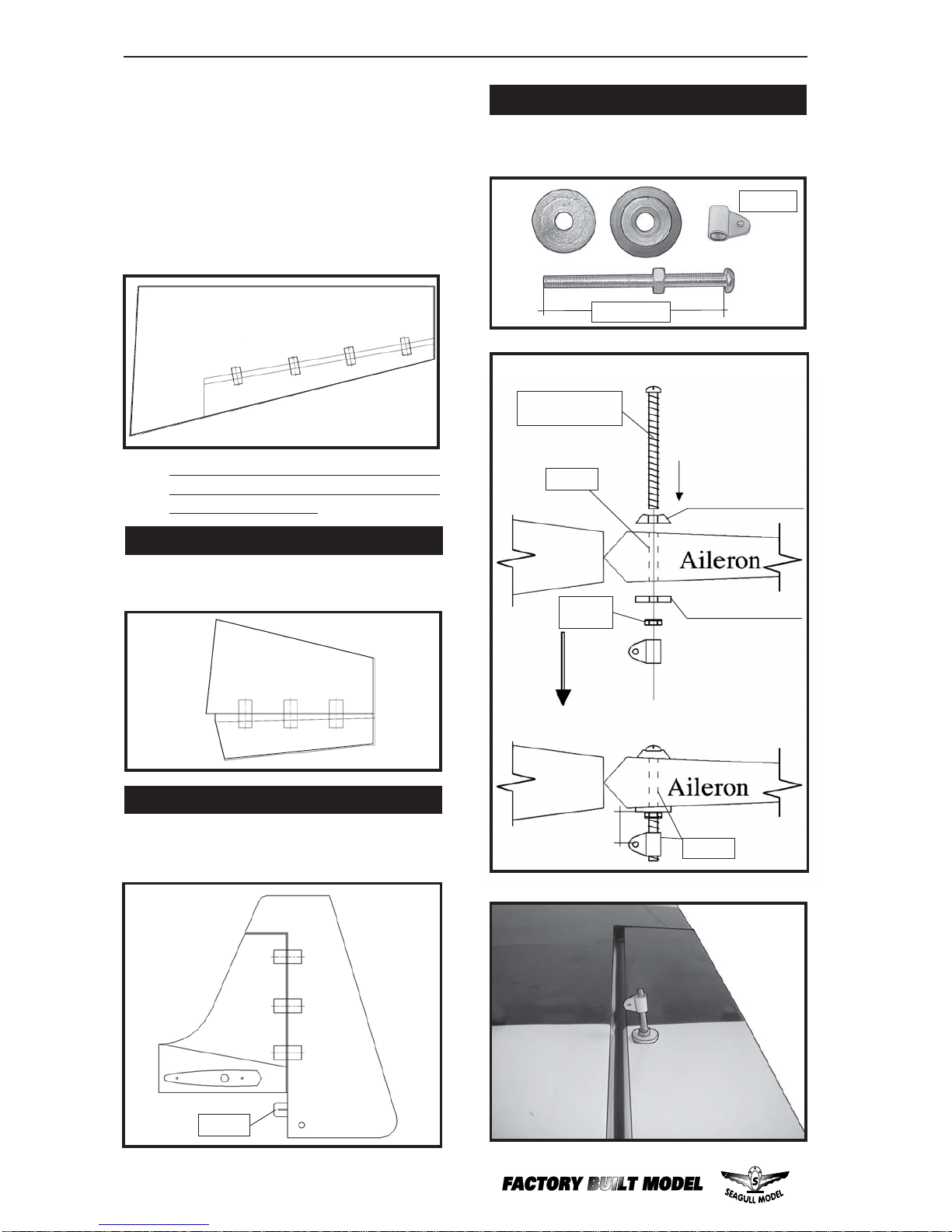
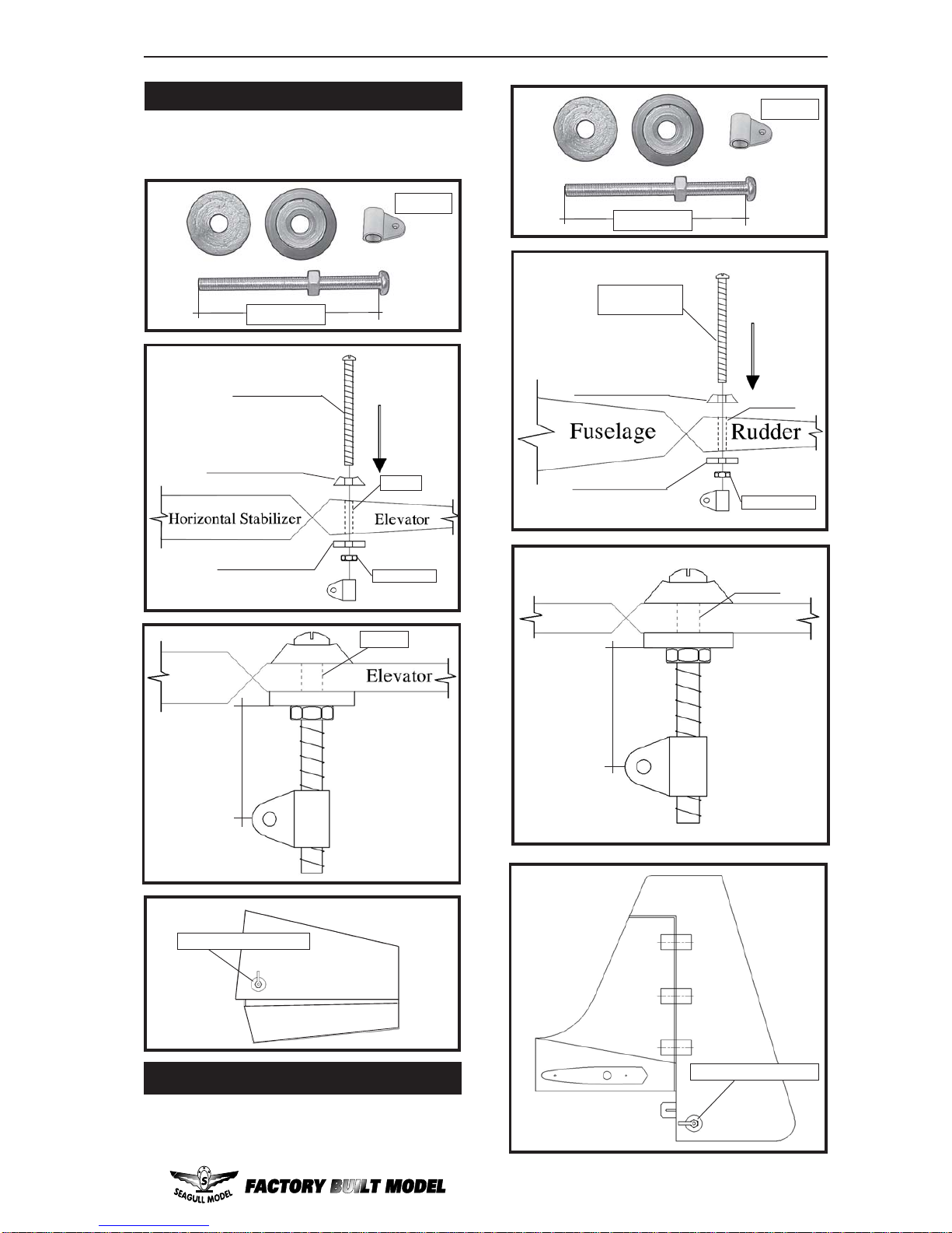
The control surfaces, including the
ailerons, elevators, and rudder, are
prehinged with hinges installed, but the
hinges are not glued in place. It is
imperativethat you properlyadhere the
hingesin place per the stepsthat follow
using a high-quality thin C/A glue.
Note:
4)Deflect the aileron and completely
saturate each hinge with thin C/A glue. The
aileronsfrontsurfaceshouldlightly contact the
wing during this procedure. Ideally, when the
hinges are glued in place, a 1/64” gap or less
will be maintained throughout the lengh of the
aileron to the wing panel hinge line.
Note: The hinge is constructed of a special
material that allows the C/A to wick or
penetrateanddistributethroughout the
hinge, securely bonding it to the wood
structureof the wingpaneland aileron.
To avoid scratching your new aero-
plane we suggest that you cover your work-
benchwith an oldtowel. Keep acouple of jars
orbowlshandytoholdthesmallpartsafteryou
open the bags.
Pleasetrialfitallparts.Makesureyouhavethe
correct parts and that they fit and are aligned
properlybeforegluing!Thiswillensureproper
assembly as the EDGE 540 is made from
natural materials and minor adjustments may
havetobemade. Thepaintandplasticparts
usedinthiskitarefuelproof.However,theyare
not tolerant of many harsh chemicals includ-
ingthefollowing:paintthinner,cyano-acrylate
glueaccelerator,cyanoacrylategluede-bonder
andacetone.Donotletthesechemicalscome
incontactwiththecoloursonthecoveringand
the plastic parts.
NOTE:
HINGING THE AILERONS.
5) Turn the wing panel over and deflect the
aileron in the opposite direction from the
opposite side. Apply thin C/A glue to each
hinge,makingsure that theC/Apenetratesinto
both the aileron and wing panel.
6) Using C/A remover/debonder and a
papertowel,remove any excessC/A glue that
may have accumulated on the wing or in the
aileronhinge area.
C/Aglue. Hinge.
Hinge.
T- pin.
Hinge.
T- pin.

EDGE 540. Instruction Manual
4
HINGING THE ELEVATOR.
8)After both ailerons are securely hinged,
firmly grasp the wing panel and aileron to
make sure the hinges are securely glued and
cannot be pulled out. Do this by carefully
applying medium pressure, trying to separate
the aileron from the wing panel. Use caution
not to crush the wing structure.
7) Repeat this process with the other wing
panel, securely hinging the aileron in place.
HINGING THE RUDDER.
Glue the elevator hinges in place using the
same tectniques used to hinge the ailerons.
Glue the rudder hinges in place using the
same tectniques used to hinge the ailerons.
Work the aileron up and down several
times to “work in” the hinges and check
for proper movement.
Note:
Aileron control horn: See pictures below.
AILERON CONTROLHORN
M3LOCK
NUT.
ALUMINUMWASHER.
ALUMINUMWASHER.
CONTRONLHORN
M3 SCREW.
16mm.
Epoxy.
Wing
Epoxy.
Wing
Hinge.
2 sets.
3x45mm.

www.seagullmodels.com
5
AluminumWasher.
CONTRONL HORN M3
M3LOCKNUT.
Epoxy.
AluminumWasher.
ELEVATOR CONTROL HORN.
Install the elevator control horn using the
same method as with the aileron control
horns.
2 sets.
3x45mm.
Rudder control horn:
Usingthesametectniques used aileron control
horn. See picture below.
16mm.
2 sets.
3x45mm.
EPOXY.
CONTRONL HORN
M3 SCREW.
ALUMINUMWASHER.
ALUMINUMWASHER.
M3LOCK NUT.
EPOXY.
Rudder control horn.
16mm.
Epoxy.
RUDDER CONTROL HORN.
Horizontal
Stabilizer.
Fuselage. Rudder.
Elevator control horn.

EDGE 540. Instruction Manual
6
2) Usinga modeling knife,cut one length
ofsiliconfuel line. Connect oneendof the line
tothe weighted fuelpick up andthe other end
to the nylon pick up tube.(The silicon tube is
not included).
3) Carefully bend the second nylon tube
up at a 45º angle. This tube is the vent tube.
1) Using a modeling knife, carefully cut
off the rear portion of one of the 3 nylon tubes
leaving 1/2” protruding from the rear of the
stopper. This will be the fuel pick up tube.
INSTALLING THE STOPPER ASSEMBLY.
Thread locker glue.
See pictures below.Make yourself the
template of your engine on paper.
ENGINE MOUNT INSTALLATION.
Mark and drill 4 holes for engine mount.
Insert 4 blind nuts to firewall.
4x30mm.
Diameter =5.5mm.

www.seagullmodels.com
7
Venttube. Fuel pick up tube.
Fuel fill tube.
4) Test fit the stopper assembly into the
tank. It may be necessary to remove some of
the flashing around the tank opening using a
modeling knife. If flashing is present, make
sure none falls into the tank.
5) With the stopper assembly in place,
the weighted pick-up should rest away from
therear of the tank andmove freely inside the
tank. The top of the vent tube should rest just
below the top of the tank. It should not touch
the top of the tank.
Important: When the stopper assembly is in-
stalled in the tank, the top of the vent tube
should rest just below the top surface of the
tank. It should not touch the top of the tank.
Carefully use a lighter or heat gun to
permenently set the angle of the vent tube.
6) When satisfied with the alignment of
the stopper assembly tighten the 3 x 20mm
machine screw until the rubber stopper ex-
pands and seals the tank opening. Do not
overtighten the assembly as this could cause
the tank to split.
FUEL TANK INSTALLATION.
You should mark which tube is the vent
and which is the fuel pickup when you
attach fuel tubing to the tubes in the stopper.
Once the tank is installed inside the fuselage,
it may be difficult to determine which is which.
Rubber band. Fueltank.
Blow through one of the lines to ensure
thefuel lines have not become kinked in-
side the fuel tank compartment. Air should
flowthrough easily.
Fuel pick-up tube.
Fuelfill tube.
Venttube.
INSTALLING THE BATTERY.
1) Assembleand mountingthewheelpants
as shown in the following pictures.
WHEEL AND WHEEL PANTS
INSTALLATION.
Battery.
Tie Wrap.

EDGE 540. Instruction Manual
8
2) Follow diagram below for wheel pant
installation:
1) The blind nuts for securing the landing
geararealready mounted insidethe fuselage.
2) Using the hardware provided, mount
the main landing gear to the fuselage.
INSTALLING THE MAIN LANDING GEAR.
3) A drop of C/A glue on the wheel collar
screws will help keep them from coming lose
duringoperation.
Repeat the process for the other wheel.
wheel collar.
wheel.
Lite-Plywood
block.
Axle.
Washer. M3. M3.
wheel Pant.
wheel.
M3.
M3.
wheel collar.
Lite-Plywood
block.
nut. Axle.
Washer.
LandingGear.
4x20mm.
14mm.
7mm.
wheel Pant.
Lockerglue.
Lockerglue.

www.seagullmodels.com
9
1) Install the pushrod housing through the
predrilledholeinthe firewall andintotheservo
compartment. The pushrod housing should
protrude 1/4" out past the front of the firewall.
MakeaZ-Bend 1/4" from oneend of the plain
wire pushrod.
MOUNTING THE ENGINE.
6) AttachtheZ-Bendin the pushrodwireto
the throttle arm on the carburetor.
5) Bolttheenginetotheenginemountusing
the four machine screws. Double check that
all the screws are tight before proceeding.
4) Remove the engine. Using an drill bit,
drill the mounting holes through the engine
mount at the four locations marked.
2) Place your engine onto the engine
mount. Adjust the engine is centered of the
edges of the engine case.
3) When you are satisfied with the align-
ment, mark the locations of the engine
mounting.
155mm
.
4.2 mm diameter.
MachineScrew 4x30mm.
COWLING INSTALLATION.
1) Slide the fiberglass cowl over the en-
gineandline up the backedgeof the cowl with
themarks you made on thefuselage then trim
and cut.
Pushrodwire.
Becauseof the size ofthe cowl, itmay be nec-
essaryto use a needle valveextension for the
highspeedneedle valve. Make thisoutof suf-
ficient length 1.5mm wire and install it into the
end of the needle valve. Secure the wire in
placeby tightening theset screw in the sideof
the needle valve.
Trim and cut.
Trim and cut.
2) While keeping the back edge of the
cowl flush with the marks, align the front of
thecowlwiththecrankshaftoftheengine. The
front of the cowl should be positioned so the
crankshaft is in nearly the middle of the cowl
opening.Usethespinner backplate as aguide.
Hold the cowl firmly in place using pieces of
masking tape.

EDGE 540. Instruction Manual
10
3) Installthemufflerandmuffler extension
onto the engine and make the cut out in the
cowl for muffler clearance. Connect the fuel
and pressure lines to the carburetor, muffler
and fuel filler valve. Secure the cowl to fuse-
lage using the 3x10mm screws (4).
Install the spinner backplate, propeller and
spinner cone.
The propeller should not touch any part
of the spinner cone. If it does, use a
sharp modeling knife and carefully trim away
the spinner cone where the propeller comes
in contact with it.
INSTALLING THE SWITCH.
Installtheswitch into theprecut hole inthe
side of fuselage.
MachineScrew 3x10mm.
1.5mmwere
(needlevalve).
Switch.
SPINNER INSTALLATION.

www.seagullmodels.com
11
THROTTLE SERVO ARM INSTALLATION.
Install adjustableservoconnectorinthe servo
arm .
2) Secure the servos with the screws pro-
vided with your radio system.
INSTALLING THE FUSELAGE SERVO.
1) Installthe rubber grommets and brass
colletsonto the throttle servo. Test fit the servo
into the aileron servo mount.
Because the size of servos differ, you
mayneedtoadjustthesizeoftheprecutopen-
ing in the mount. The notch in the sides of the
mount allow the servo lead to pass through.
Throttleservo.
Elevatorservo.
Elevatorservo.
Rudderservo.
Throttleservoarm.
Elevatorservo.
Elevatorservo.
Rudderservo.
VERTICAL STABILIZER INSTALLATION.
Remove the covering as picture shown
below.
Maskingtape.
Removecovering.
Fill epoxy.
Removethecovering.
AdjustableServo
connector.
Servoarm.
Loctite secure.
1PCS.
Removethecovering.

EDGE 540. Instruction Manual
12
Hingeslot.
Epoxy.
C/Aglue.
Hinge.
Hinge.
INSTALLING HORIZONTAL FIN.
1) Remove the covering as same as
pictures shown below.
2) Sand the aluminium tube using
sandpaper. This will improve the bond of the
epoxy to the cardboard horizontal fin.
Coatbothsidesofonehalfofthealuminium
tube with 30 minute epoxy. Next, pour some
epoxy into the cardboard horizontal fin. Use
enough epoxy to fill any gaps.
Epoxy.
3) Insert aluminiumtubeinto thecardboard
of fuselage.
Epoxy.
Epoxy.
4) Slide the two horizontal fin halves to-
getherandcarefullyalignthemat thepossition
onthefuselage.Wipeawayanyexcessepoxy
using paper towels.
Aluminiumtube.
335mm.
Covering strip.
Covering strip.

www.seagullmodels.com
13
Epoxy. Epoxy.
INSTALLING THE AILERON SERVOS.
String.
Small weight.
Servos. Smallweight.
Thread.
Installing the aileron servo in place using the
same techniques used to flap servo.
Electric wire.
Aileron
Servo.
Attach the string to the servo lead and carefully thread it though the wing.
String. Small Weight.
Wing. Wing rib.
String.
Small Weight.

EDGE 540. Instruction Manual
14
Aileron.
Wing.
Wing.Aileron.
AILERONPUSHROD HORN INSTALLATION
Wing.
Aileron.
ELEVATOR - RUDDER PUSHROD HORN
INSTALLATION.
Repeat the procedure for the other wing.
Elevator control horn.
Rudder control horn.
Wing. Aileron.
M2lock nut.
1)Elevatorand rudder pushrods assembly
follow pictures below.
M2 Lock nut.M2clevis.
Attach to servo arm in fuselage. Attach to elevator - rudder control horn.
M2 lock nut.
M2clevis.
75mm.
110mm.

www.seagullmodels.com
15
Rudder pushrod.
Control horn.
Elevator Pushrod.
Metalclevis.
Elevator pushrod.
M2lock nut.
Elevator.
Elevator.
Rudder.
Throttle.
2) Install servos arm to servos. Notice the
position of the servo arms on the servos. See
picture below.
Elevator.
Rudder.
Throttle.
3x25mm.
MOUNTING THE TAIL WHEEL.
Seepicturebelow.
3x30mm.

EDGE 540. Instruction Manual
16
Tail landinggear.
Spring.
3x25 mm.
3x30 mm.
1) Plug the six servo leads and the switch
lead into the receiver. Plug the battery pack
lead into the switch also.
2) Wrap the receiver and battery pack in
the protective foam rubber to protect them
from vibration.
3) Route theantennain the antennatube
inside the fuselage and secure it to the bot-
tom of fuselage using a plastic tape.
INSTALLING THE BATTERY-RECEIVER.
Antenna.
Receiver.
ATTACHMENT WING-FUSELAGE.
Attach the aluminium tube into fuselage.
Insert two wing panels as pictures below.
Wing tube.
3x30 mm.

www.seagullmodels.com
17
Wing bolt.
1) It is critical that your airplane be bal-
anced correctly. Improper balance will cause
yourplaneto lose controlandcrash. The cen-
ter of gravity is locate 6.5-7.5cm back from
theleadingedge of thewing,measuredatwing
tip.
BALANCING.
2) If the nose of the plane falls, the plane
is nose heavy. To correct this first move the
battery pack further back in the fuselage. If
this is not possible or does not correct it, stick
small amounts of lead weight on the fuselage
sides under the horizontal stabilizer. If the tail
of the plane falls, the plane is tail heavy.
To correct this, move the battery and receiver
forward orif this is not possible, stick weight
ontothe firewall.When balancedcorrectly,the
airplane should sit level or slightly nose down
when you lift it up with your fingers.
1) We highly recommend setting up the
EDGE 540 using the control throws listed at
right. We have listed control throws for both
Low Rate (initial test flying/sport flying) and
High Rate (aerobatic flying).
CONTROL THROWS.
6.5-7.5cm.
4x15mm.
3) When the elevator, rudder and aileron
control surfaces are centered, use a ruler and
check the amount of the control throw in each
surface. The control throws should be
measured at the widest point of each sur-
face!
2) Turn on the radio system,and withthe
trim tabs on the transmitter in neutral, center
the control surfaces by making adjustments
totheclevisesor adjustable servo connectors.
The servo arms should be centered also.

EDGE 540. Instruction Manual
18
E)Checkthe throttle. Moving the throttle
stick forward should open the carburetor bar-
rel. Ifitdoesnot,fliptheservoreversingswitch
on your transmitter to change the direction.
PREFLIGHT CHECK.
D) Check the rudder. Looking from be-
hindthe airplane, move the rudder stick to the
right. Theruddershould move to theright. Ifit
does not, flip the servo reversing switch on
your transmitter to change the direction.
4) By moving the position of the adjust-
able control horn out from the control surface,
you will decrease the amount of throw of that
control surface. Moving the adjustable con-
trol horn toward the control surface will in-
crease the amount of throw.
FLIGHT PREPARATION.
A) Check the operation and direction of
the elevator, rudder, ailerons and throttle.
C) Check the elevator first. Pull back on
theelevator stick. The elevatorhalves should
move up. If it they do not, flip the servo re-
versing switch on your transmitter to change
the direction.
F) From behind the airplane, look at the
aileronontheright wing half. Move theaileron
sticktotheright. Theright aileron should move
upandthe other aileronshould move down. If
it does not, flip the servo reversing switch on
your transmitter to change the direction.
INITIALFLYING
AEROBATICFLYING
Do not use the aerobatic settings for
initialtest flying or sport flying.
1) Completely charge your transmitter
and receiver batteries before your first day of
flying.
B) Plug in your radio system per the
manufacturer's instructions and turn every-
thingon.

www.seagullmodels.com
19
5) If your radio transmitter is equipped
withdual rate switchesdouble check thatthey
are on the low rate setting for your first few
flights.
6) Check to ensure the control surfaces
are moving the proper amount for both low
and high rate settings.
8) Properly balance thepropeller. Anout
of balance propeller will cause excessive vi-
bration which could lead to engine and/or air-
frame failure.
We wish you many safe and enjoyable
flights with your EDGE 540 .
7) Check the receiver antenna. It should
be fully extended and not coiled up inside the
fuselage.
2) Check every bolt and every glue joint
in the EDGE 540 to ensure that everything is
tight and well bonded.
3) Double check the balance of the air-
plane. Do this with the fuel tank empty.
4) Check the controlsurfaces. All should
move in the correct direction and not bind in
any way.
Table of contents