01/24/2020 Version 3.3.1
Components Needed from Your Existing Shapeoko Setup
The only components you need to transfer from your existing X/Z-carriage are:
• X- and Z-Homing Switches and Hardware
• X- and Z-Motor
• Spindle Mount
• Spindle/Router
HDZ Kit Contents
Each HDZ comes with the following standard hardware (everything required to install it to your Shapeoko):
• EZTram Router/Spindle Mounting Plate (1)
• M5 x 18mm Screw for Top of EZTram Plate (2)
• M5 x 10mm Screw for Bottom of EZTram Plate (2)
• Eccentric Spacer (non-threaded) for EZTram (2)
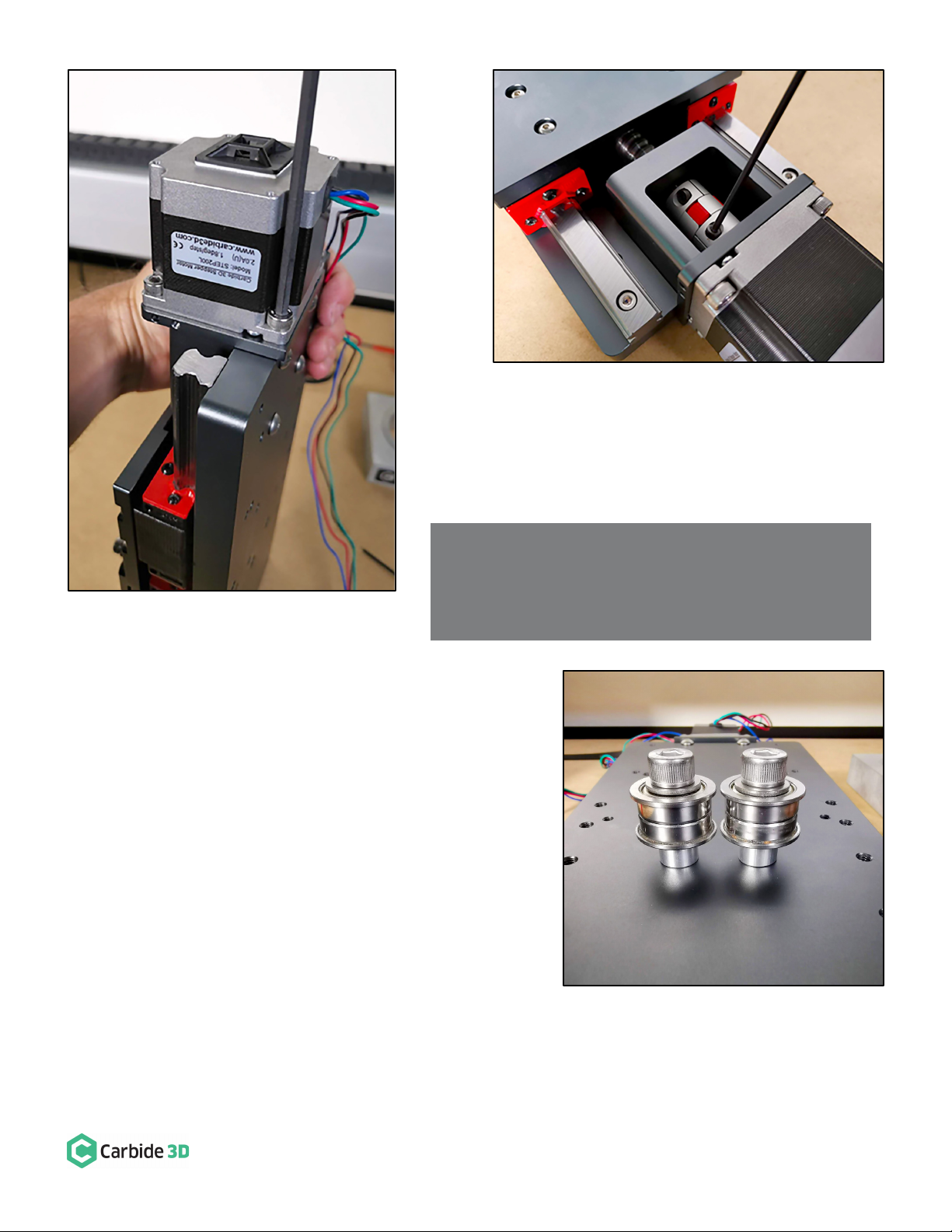
• Z-Motor Shaft Coupling (1)
• M5 x 25mm Male-Female Threaded Standoff for the
X-Motor (4)
• M5 x 10mm Screw for Motor Standoffs (8)
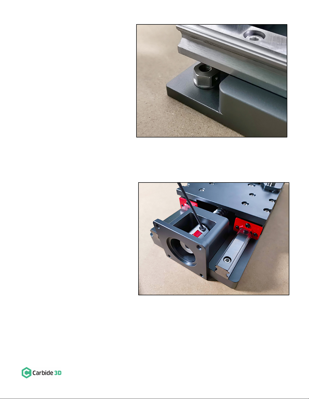
• HD Eccentric Nut (2)
• Replacement V-Wheel (4)
• V-Wheel Shim (4)
• M5 x 25mm Screw for V-Wheel (4)
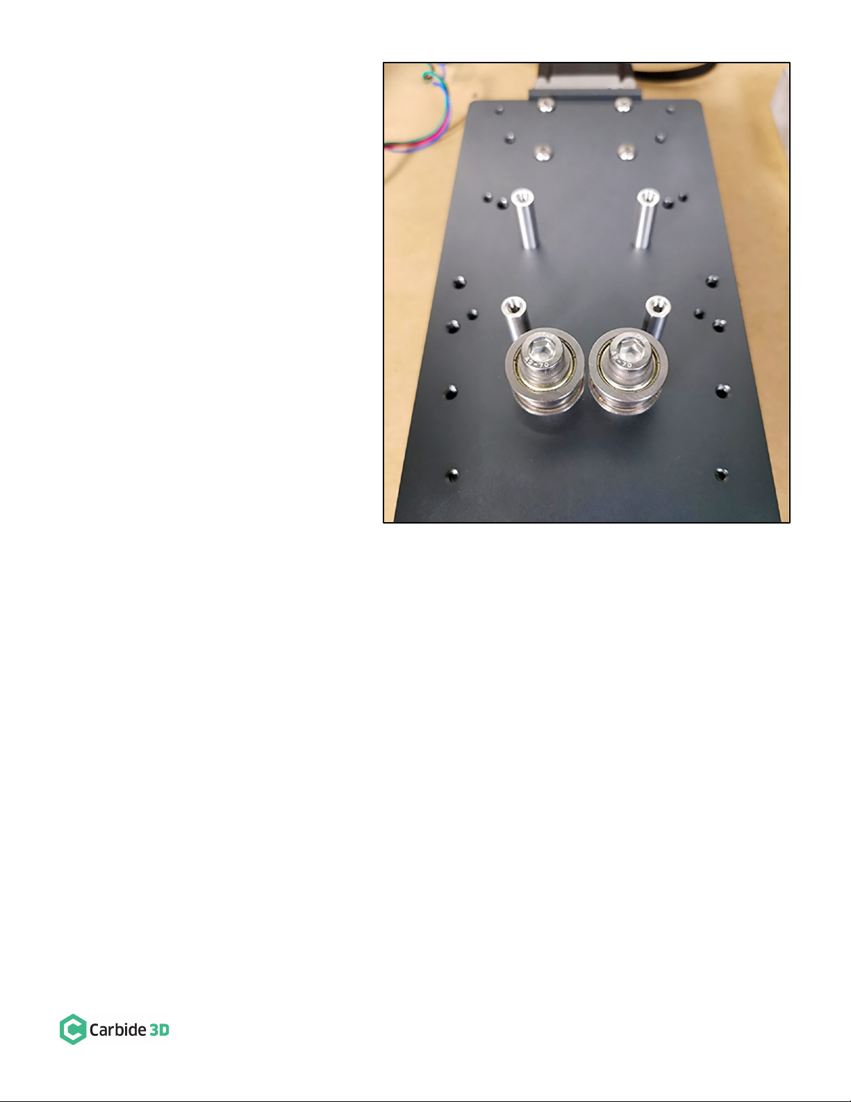
• M8 x 30mm X-Motor Idler Bolt (2)
• M8 Washer (2)
• M8 Spacer (2)
• M8 Guide Bearing (4)
• Green Dust Cap (10)
• Black Sledge (4)
Disassemble and Remove the Existing X/Z Carriage
The first step is to disassemble and remove the existing X/Z-carriage from your Shapeoko.
1. Turn off your machine and unplug it. Disconnect the USB cable.
2. Unplug the router or spindle and remove it from the spindle mount.
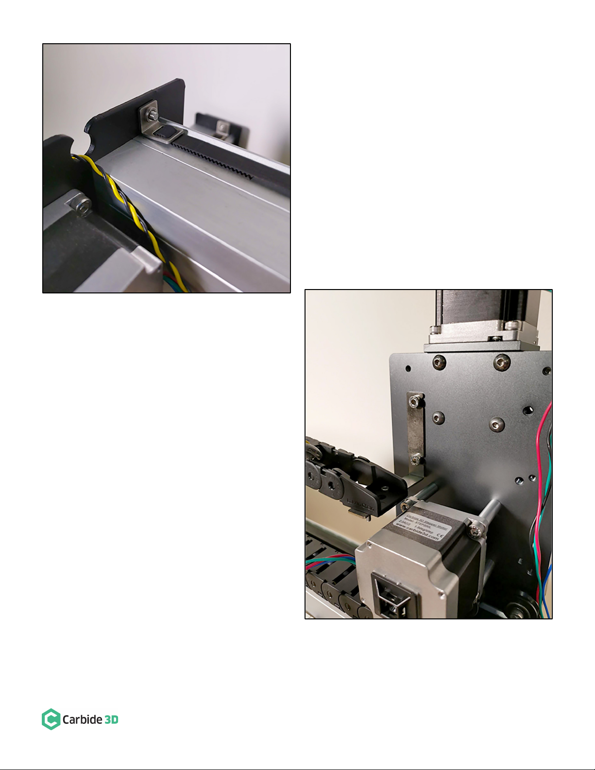
3. Remove one of the belt clips securing the x-axis belt to the X-rail. Unfeed the belt from the X/Z-carriage idler
pulleys and put the free end of the x-axis belt, the belt clip, and the M5 x 10mm screw to the side—you will
need to re-install them later.
4. Label, then disconnect the Z- and X-motor wires.
5. Remove the z-axis homing switch from the front of the X/Z-carriage.
6. Remove the z-axis homing switch from its mounting plate. Set the z-axis homing switch hardware, the M3
screw, washer, and lock nut, aside for the HDZ assembly (we won’t be needing the mounting plate or the four
M5 screws).
7. Remove the x-axis homing switch from the rear of the X/Z-carriage, below the drag chain bracket. Set the two
M5 x 35 mounting screws and 1-inch spacers aside, we’ll need them to re-install the homing switch onto the
HDZ.
8. Remove the x-axis homing switch from the mounting plate. Set the mounting plate and hardware, the M3
screw, washer, and lock nut, aside for re-installation.