Edgetec TRIFLO User manual

Owner's Manual
Triflo Spa Bath Pump

EDGETEC SYSTEMS PTY LTD Part # 9-2100 MAY 2012
2
Suction
Mini Jet
Return Line
Self Drain Tee
Suction Line
(Minimum 5°
Gradient)
Jet
Diagram 1 Correct Spa Bath Pump Installations
Use 40mm or 25mm UPVC Pressure Pipe for plumbing installation,
40mm pipe is preferred for both the suction and return lines.
IMPORTANT REQUIREMENT:
Installation of the TriFlo pump must have access for servicing the pump
or pipe work. A service access panel must be provided so that the
pump can be easily removed for service (if required) on every
installation.
Self Drain Tee
Suction Line
(Minimum 5°
Gradient)
Suction
Jet
Return Line
Self Drain Tee
Suction Line
(Minimum 5°
Gradient)
Suction
Jet
Return Line

EDGETEC SYSTEMS PTY LTD Part # 9-2100 MAY 2012
3
Diagram 2 Incorrect Spa Bath Pump Installations
TriFlo Technical Data
Pump Model
Supply
Voltage
Power
(watts)
Heater
(watts)
Current
(amps)
Max
Head m
Width
(mm)
Height
(mm)
Length
(mm)
TF060-AH-50
230-240
600
0
3.7
11
148
198
384
TF075-AH-50-HF
230-240
750
0
4.4
11
148
198
384
TF110-AH-50
230-240
1100
0
5.4
11
148
198
406
TF060-XH, ET, ST, SK-50
230-240
600
700
6.8
11
148
198
384
TF075-XH, ET,ST, SK-50-HF
230-240
750
700
7.5
11
148
198
384
TF110-XH, ET,ST, SK-50
230-240
1100
700
8.6
11
148
198
406
Jet
Suction
Suction
Jet
Jet
Suction

EDGETEC SYSTEMS PTY LTD Part # 9-2100 MAY 2012
4
Diagram 3 Air Tube Connections
Diagram 4 Activating Air Bleed
*Important - Only Activate Air Bleed if pump does not
prime (refer page 10)
Prior to August 2012
After August 2012
Twist Cap Air Bleed - Rotate
Fully Anticlockwise to Open
Attach 10 mm
Flexible drain tube
(Not Supplied)

EDGETEC SYSTEMS PTY LTD Part # 9-2100 MAY 2012
5
Diagram 5 Touch Pad Connection

EDGETEC SYSTEMS PTY LTD Part # 9-2100 MAY 2012
6
TriFlo Spa Bath Pump
Congratulations on the purchase of your new TriFlo spa bath pump. The TriFlo spa bath
pump has been specifically designed for spa bath applications to ensure that you have
optimum spa jet performance and many years of trouble free operation.
The TriFlo pump internal design allows the water to self drain so that there is no residue
water left in the pump when the spa is emptied in accordance with Local Health
Regulations.
TriFlo spa bath pumps are designed for spa bath operation only and should not be used in
chemically treated water or any other purpose without seeking written approval from
Edgetec Systems Pty Ltd for the application.
TriFlo Models and Operation Guide
Auto-Heat: The “Auto-Heat” TriFlo will help maintain your spa bath water
temperature during your spa by heat transfer. This pump is activated by the air
button installed on your bath.
Xtra-Heat: The “Xtra-Heat” TriFlo has the revolutionary flat plate 700watt Stainless
Steel heater built into the pump, this will maintain your spa bath water temperature
even in the largest spa baths. This pump is activated by the air button installed on
your bath.
EEZI-Touch: The “EEZI-Touch” TriFlo has the revolutionary
flat plate 700watt Stainless Steel heater built into the pump
and a bath mounted touch pad which allows you to
control the pump from the baths edge.
Depressing the touch pad button will turn your pump “on
or off”. When operating the Blue Led will light up.
The heating function will automatically come on once the pump has primed and
water is detected in the spa bath pump.
The Green indicator light on the touch pad is showing that the communication cable
from the pump is fitted correctly and that there is power to the spa bath pump
Sensa-Touch: The “Sensa-Touch” TriFlo has an integral flat plate 700watt Stainless
Steel heater built into the pump and a bath mounted touch pad which allows you to
control the Pump & Heater function from the baths edge.
Depressing the Pump button will turn your pump “On or Off”, if there is no water in the
spa bath or insufficient water in the pump the pump will automatically shut down to
protect your pump from running dry and causing potential damage.
The heating function will automatically come on once the pump has primed and
water is detected in the spa bath pump.
The Red heater indicator lights will flash in
sequence to indicate that the water is now
being heated. When the water temperature has
reached the setting chosen or the bath water is
at the set temperature the red lights L, M or H will
stay on depending on the setting chosen. To turn
the heating down press the heater button, each
time you press the heater button an indicator
light will turn off and the set temperature will be
reduced, when all the lights are off the heater is no longer active. To turn the heater

EDGETEC SYSTEMS PTY LTD Part # 9-2100 MAY 2012
7
back on, press the heater button and the heater will come back on at the highest
setting.
The Green indicator light in the centre of the touch pad is showing that the
communication cable from the pump is fitted correctly and that there is power to the
spa bath pump.
Spa-Key: The “Spa-Key” has an integral flat plate 700watt Stainless Steel heater
built into the pump. The Spa-Key is a unique radio operated remote control system
which is housed in an immersible casing. The Spa-Key operates the pump, and
heater –and has additional buttons to switch on a Spa Blower and Light –all in the
one small casing. The Spa-Key is installed on the wall near the door in a moulded
housing, from where it can operate any of the four functions of the highly
sophisticated spa bath. The Spa-Key can be removed from the housing and carried
around the bathroom to provide a sophisticated control function even while you are
relaxing inside the bath. The Spa-Key will even function underwater –although we
do not encourage submersion. The Spa-Key has a replaceable long life battery.
Depressing the Pump button will turn your pump “On or Off”, if there is no water in the
spa bath the pump will automatically shut down to protect your pump from running
dry and causing potential damage to your pump.
The heating function will automatically come on
once the pump has primed and water is detected in
the spa bath.
To turn the heater “On or Off” depress the heater
button on the remote control.
To turn the Spa Blower (where fitted) “On or Off”
depress the Spa Blower button on the remote
control.
To turn the Light (where fitted) “On or Off” depress
the Light button on the remote control.
Extra or Replacement Hand Set. Can be
programmed by pressing the reset button at the
back of the pump, and pressing the PUMP key on the SPA-KEY handset within 30
seconds, refer www.spakey.com.au for further technical information.
Your hand set that is provided with your pump has already been programmed
during assembly and is ready to use.

EDGETEC SYSTEMS PTY LTD Part # 9-2100 MAY 2012
8
Installation Instructions (refer diagram 1)
1. To ensure optimum performance of your spa bath the TriFlo pump should be
located as close as possible to your spa bath. To ensure high efficiency of
your TriFlo pump, use the minimum amount of pipe fittings during your pump
to spa bath installation. Correct installation allows water to drain from pipe
work to pump and from pump to the self drain suction fitting in the bath.
2. The pump can be located internally or externally. If you are fitting the pump
externally, we recommend that the pump have a protective cover with
adequate ventilation (minimum area 50cm²).
3. Internal installation must have adequate ventilation (minimum area 50cm²)
for the pump motor. Inadequate ventilation may cause the motor to over
heat and cut out on thermal over load.
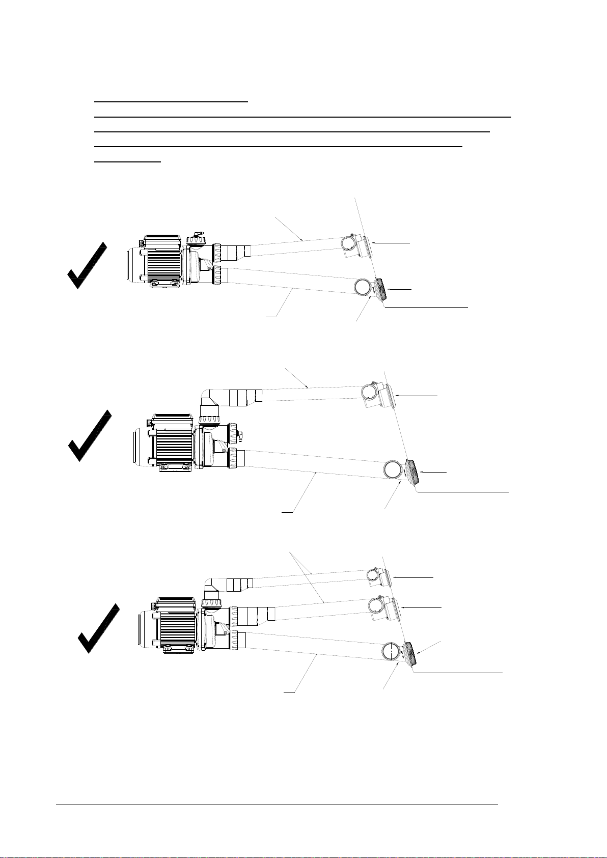
4. Install the TriFlo pump as per diagram 1 (using the least amount of elbows, if
required). It is most important that the suction line be installed with a
minimum of 5º gradient (refer Diagram 1) as this allows the water to drain
from the pump and pipe work when the bath is emptied.
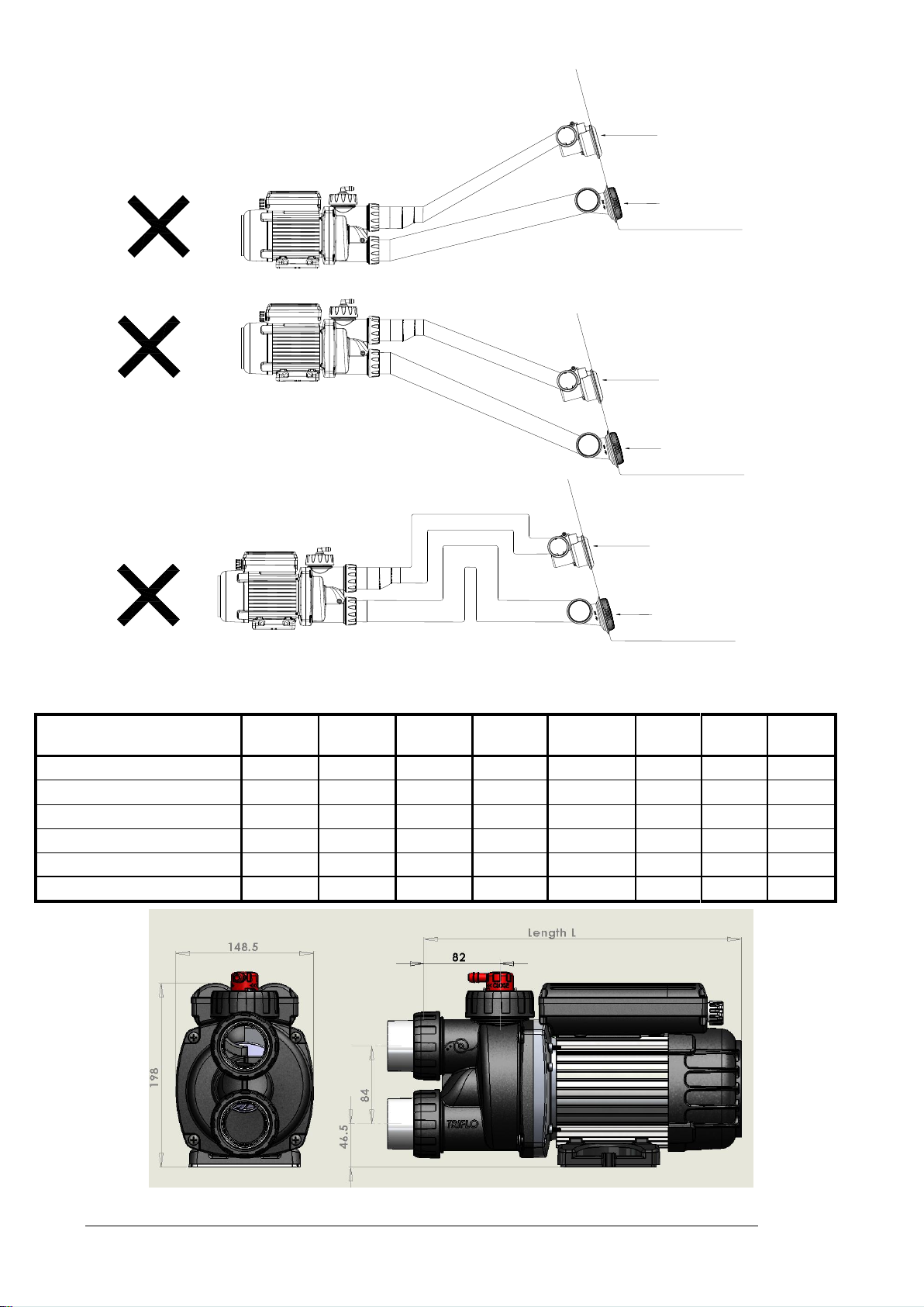
5. The pump should never be installed as shown in diagram 2
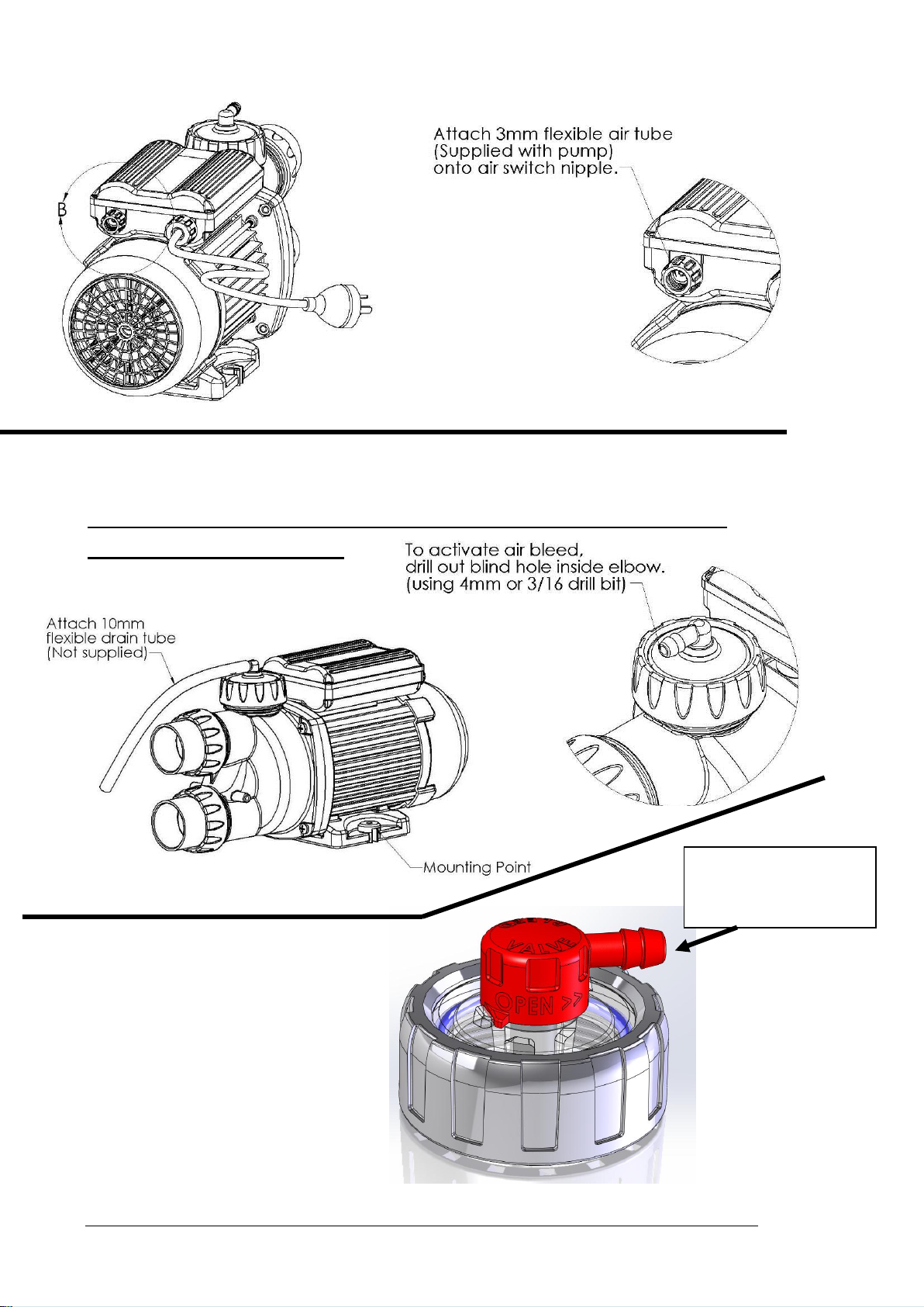
6. The pump return line should be installed below the water level of the bath, if
the return line is above the water level the pump can air lock and may not
prime (pump will start but the spa bath jets are not operating). Should this
occur you will have to activate the air bleed valve located on the pump
(Refer to Activating Air Bleed; diagram 4).
7. The pump to be fixed to the frame or support through the pump mounting
points in the pump base (refer Diagram 4) with appropriate fasteners. Two
anti-vibration isolation washer buttons are provided with the pump for the
fasteners.
8. Barrel unions only require to be hand tightened, over tightening may cause
damage to the unions and or o rings. Do not use stillsons or any other
mechanical leverage.
9. Before connecting the pump to the pipe work, ensure that all the pipe work is
clear of any debris as small particles can cause blockage to spa jets or the
pump impeller causing serious damage.
10. IMPORTANT REQUIREMENT:
Installation of the TriFlo pump must have access for servicing the pump or
pipe work. A service access panel must be provided on every installation to
allow pump removal for service (if required)
Electrical Connection
1. Spa bath pumps must be fitted in accordance with the relevant national
wiring rules and electrical standards, particularly AS 3000 or equivalent.
2. The TriFlo spa bath pump is fitted with a standard lead and three pin plug for
240-220V 50Hz power supply.
3. The spa bath pump power connection must be accessible so that it can be
independently switched off in case of an emergency but must not be
accessible by the bath user.
4. Edgetec highly recommends that the pump be supplied by an isolating
transformer or supplied through a residual current device (RCD) with a rated
residual operating current < 30 mA.
5. If damage occurs to the power cord it must be replaced by Edgetec or an
authorised service agent or suitably qualified person.

EDGETEC SYSTEMS PTY LTD Part # 9-2100 MAY 2012
9
Your spa bath pump should be installed on a well drained location or
on a suitable drain tray to avoid water damage to property should any
leaks occur from pipe work, connections or normal wear.
Air Tube Connection “Auto-Heat & Xtra- Heat Models” (refer diagram 3)
1. Supplied with your spa pump is a 4 metre roll of 3mm clear air tube, fit one
end of the air tube to the air button (supplied with the spa bath) on the spa
bath.
2. Uncoil the air tube so that you can connect it to the air switch located on the
pump (refer diagram 3) at the rear of the pump motor on the capacitor
cover.
3. Cut off excess tube and ensure that the tube is not kinked, do not wrap or
loop excess tube around frame work of the bath or pipe work as this may
cause the air button not to operate correctly.
Touch Pad Cable Connection “Sensa-Touch Model” (refer diagram 5)
1. Supplied on your spa bath is the Sensa Touch Pad, connected to the touch
pad will be a 4 metre data cable.
2. Uncoil the data cable and you will see that one end is already connected to
the touch pad on the spa bath.
3. Connect the other end to the pump as per diagram 5, ensuring that the data
cable connection clip is being inserted correctly. Push the clip in until you
hear it “click” into the fixed position.
4. Push the protective rubber cap that is on the cable over the circular housing
(refer diagram 5) to protect the touch pad cable connection. Failure to do
this may void your warranty.
5. When power is activated there will be a “Green”indicator light activated on
the touch pad to show that the connection is fitted correctly from the pump to
the touch pad.
Start Up
1. Fill the spa bath to approximately 50mm above the spa jets, check the pump
and pipe connection for any leaks.
2. Ensure that the pump power outlet is switched to the “on“ position.
3. Auto-Heat & Xtra-Heat pumps. Press the air button on the spa bath, the pump
will start and purge the air from the system and your spa will start to operate.
To stop the spa, simply press the air button again.
4. Sensa-Touch pump. Press the pump symbol on the touch pad, the pump will
start and purge the air from the system and your spa will start to operate. To
stop the spa, simply press the pump symbol on the touch pad.
5. Spa-Key. Press the pump symbol on the hand set, the pump will start and
purge the air from the system and your spa will start to operate. To stop the
spa, simply press the pump symbol on the hand set.
6. If the pump fails to prime you may have an air lock, please refer to activating
air bleed.
!
Never run your spa pump without water as this can cause
serious damage to the mechanical seal which may cause the
spa pump to leak. Running the pump without water will void
your warranty.
!

EDGETEC SYSTEMS PTY LTD Part # 9-2100 MAY 2012
10
Activating Air Bleed
Prior to August 2012 the air bleed fitted was a sealed unit which required a drill operation
to activate the air bleed.
From August2012 the Air Bleed has a Twist Cap which will open the Air Bleed when the
Cap is rotated Fully Anticlockwise. (No Drilling Required)
(Pre August 2012) - refer diagram 4
1. The air bleed valve is manufactured in the closed position and if your pump is
installed as per diagram 1 you will not need to activate this valve.
2. If your spa pump is not priming, you will have to activate the air bleed valve. To
do this you will require a 4mm or 3/16 drill bit. Carefully drill out the blank in the
air bleed elbow ensuring that you do not drill through the outer wall (refer
diagram 4), the air bleed valve is now activated.
3. It is common for air bleed valves to “Squirt” water when sealing, this will occur
every time the pump is switched on. Once the internal valve is seated, the water
“squirt” will stop.
4. To avoid any water damage, we recommend that you place a 10mm tube (not
supplied) over the air bleed barb and place the tube in a position where the
excess water will not cause any damage (i.e. into a drain or outside).
From August 2012
From August 2012 the Air Bleed has a Twist Cap which will open the Air Bleed when
the Cap is rotated Fully Anticlockwise.
Rotating the Twist Cap Fully Clockwise will Close the air Bleed.
The pump is shipped with the air bleed in the closed position.
1. The air bleed valve is supplied in the closed
position and if your pump is installed as per
diagram 1 you will not need to activate this
valve.
2. If your spa pump is not priming, you will
have to activate the air bleed valve. To do
this Rotate the Red Cap air Bleed valve Fully
Anticlockwise - the air bleed valve is now
activated.
3. It is common for air bleed valves to “Squirt”
water when sealing, this will occur every
time the pump is switched on. Once the
internal valve is seated, the water “squirt”
will stop.
4. To avoid any water damage, we recommend that you place a 10mm tube (not
supplied) over the air bleed barb and place the tube in a position where the
excess water will not cause any damage (i.e. into a drain or outside).

EDGETEC SYSTEMS PTY LTD Part # 9-2100 MAY 2012
11
Trouble Shooting Guide
Auto-Heat & Xtra-Heat - Spa Pump will not start
Possible Cause
Suggested Action
Air tube is not
connected
Check to ensure that the air tube is connected to the air button on the spa
bath and the air switch on the pump
Air Tube is kinked
Check to ensure that the air tube is not kinked or wrapped around the frame
work as this will stop the pulse of air required to come from the air button
Air button is not
operating
Check to ensure that the air button is clear of debris (i.e. tile grout) and that
the air button plunger moves freely.
Mains Power to pump is
not switched on
Check that the power point is in the “on” position
Check the Power Point has 240V Power
Pump is not Priming - No water coming from jets
No water is coming
from spa jets
Activate Air Bleed
Refer to activating Air Bleed
No water coming from
Spa Jets
Most spa jets are now adjustable ensure that all the spa jets are in the open
position by rotating the jet face
Faulty Pump Air switch
Contact service technician.
EEZI & Sensa-Touch - Spa Pump will not start
Possible Cause
Suggested Action
Mains Power to pump is
not switched on
Check the Power Point has 240V Power
Check that the power point is “on”. Green indicator light should be glowing
on the hand set to indicate power.
Communication Cable
is not connected
Check to ensure that the communication cable is connected to the Touch
Pad and the communication port on the pump. Green indicator light should
glow on the touch pad to indicate power
Faulty Touch Pad or
Pump
Contact service technician.
Mains Power to pump is
not switched on
Check that the power point is in the “on” position
Check the Power Point has 240V Power
Pump is not Priming - No water coming from jets
No water is coming
from spa jets
Activate Air Bleed
Refer to activating Air Bleed
Pump runs but stops
after 20 seconds Sensa
Touch Only.
Most spa jets are now adjustable ensure that all the spa jets are in the open
position by rotating the jet face
No water coming from
Spa Jets
Contact service technician.
Spa-Key - Spa Pump will not start - www.spakey.com.au
Possible Cause
Suggested Action
Mains Power to Spa
pump not switched on
Check the Power Point has 240V Power
Check that the power point is “on”. Green indicator light should be glowing
on the hand set to indicate power.
Batteries are flat or not
installed in Hand Set
Check to ensure that the batteries are installed in your hand set or press any
button on the hand set, if the Red indicator lights OK - batteries are not flat.
Faulty Hand set or Pump
Contact service technician or for further technical information Visit the Spa-
Key web site
Mains Power to Spa
pump not switched on
Check that the power point is in the “on” position
Check the Power Point has 240V Power
Pump is not Priming - No water coming from jets
No water is coming
from spa jets
Activate Air Bleed
Refer to activating Air Bleed
No water coming from
Spa Jets
Most spa jets are now adjustable ensure that all the spa jets are in the open
position by rotating the jet face
No water coming from
Spa Jets
Contact service technician.

EDGETEC SYSTEMS PTY LTD Part # 9-2100 MAY 2012
12
Edgetec Product Warranty
Edgetec Systems Pty Ltd warrants that the items sold hereunder shall be free from defects in
material and workmanship for a period of one (1) year at the time of the original purchase
date and to the original purchaser.
Terms & Conditions
1. This product is to be installed in accordance with the installation and operating instructions
provided, failure to do so will void your warranty.
2. The product warranty does not cover:
fair wear and tear, negligence, misuse or abuse,
incorrect installation or running the pump dry,
water damage from external sources or inadequate ventilation,
cement or other building debris blocking the pipe work or impeller,
chemically treated water,
high voltage spikes or acts of nature,
repairs by unauthorised persons,
Incorrect voltage.
Edgetec Systems Pty Ltd has service agents throughout Australia, should you require
warranty service please contact our service department for your nearest service agent.
Edgetec Systems Pt y Ltd goods come with guarantees that cannot be excluded under the
Australian Consumer Law. You are entitled to a replacement or refund for a major failure and
compensation for any other reasonably foreseeable loss or damage. You are entitled to
have the goods repaired or replaced if goods fail to be of acceptable quality and the failure
does not amount to a major failure. No unauthorized personnel can make any warranty
representation on the behalf of Edgetec Systems Pty Ltd unless with their written permission.
Commercial Installation
Commercial Warranty: Has a limited warranty of (6) months from the date of purchase to
these commercial installations include (but not limited to) hotels, motels, caravan parks and
health clubs installations etc.
13 Lieber Grove
Carrum Downs Victoria
3201 Australia
Tel: (613) 9775 0882
Fax: (613) 9775 0881
Email: [email protected]
Web: www.edgetec.net
Proudly Australian Owned
This appliance is not intended for use by persons (including children)
with reduced physical, sensory or mental capabilities, or lack of
experience and knowledge, unless they have been given supervision
or instruction concerning use of the appliance by a person
responsible for their safety.
!
This appliance is not intended for use by young children
or infirm persons without supervision
!
This manual suits for next models
15
Table of contents
Other Edgetec Water Pump manuals
Popular Water Pump manuals by other brands

Libel
Libel XTRA 350i operating instructions

Kremlin-Rexson
Kremlin-Rexson AIRMIX 20-15 Original manual

Viking pump
Viking pump 323A Series Technical & service manual

Linde
Linde HPR-2 manual

ITT
ITT Goulds Pumps Marlow 20EVP Series Installation, operation and maintenance instructions

NOVELCA
NOVELCA JDP550PD user guide