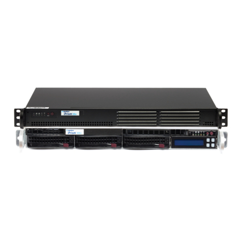
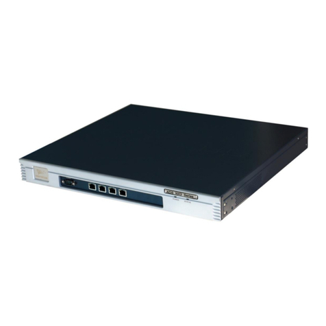
EdgeWave iPrism ERS Installation instructions

Hardware Guide
800-782-3762
www.edgewave.com
iPrism Web Security
ERS
ERS

ERS Hardware Guide 2
© 2001 – 2008 St. Bernard Software Inc. All rights reserved. The St. Bernard Software logo,
iPrism, iGuard and ERS are trademarks of St. Bernard Software Inc. All other trademarks and
registered trademarks are hereby acknowledged.
Other product and company names mentioned herein may be the trademarks of their respective
owners.
The iPrism software and its documentation are copyrighted materials. Law prohibits making
unauthorized copies. No part of this software or documentation may be reproduced, transmitted,
transcribed, stored in a retrieval system, or translated into another language without prior
permission of St. Bernard Software, Inc.
ERS001.3.0.0001

ERS Hardware Guide 3
Contents
ERS Hardware ....................................................................................................................4
Front and Back Covers.....................................................................................................4
LEDs and Lights...............................................................................................................5
Power Supplies ................................................................................................................6
Installing the ERS M6200 Appliance................................................................................6
Contacting St. Bernard Software Technical Support .....................................................7

ERS Hardware Guide 4
ERS Hardware
Front and Back Covers
Figure 1: ERS M6200 with cover installed
Figure 2: ERS M6200 Front Panel (with cover removed)

ERS Hardware Guide 5
LEDs and Lights
•Ethernet Interface #1/#2 Activity Light: Blinking green indicates that data is passing
through the management interface. Steady green indicates the management interface is
connected.
•On/Off Switch: When power is not applied to the system, press this switch to power the
ERS appliance.
Important: When power is ON, always use the Exit > Shutdown option from within the
ERS System Configuration tool to power down your ERS appliance. This cleanly
terminates the current ERS services and network connections and prepares ERS to be
powered down using this button.
•Power LED: This LED indicator illuminates when power is applied to the system.
•HDD LED: Indicates disk activity.
•System Fault LED: Solid green indicates normal operation. Blinking green indicates that
the system is working, but in degraded mode. This can occur when the system becomes
overheated, so check for adequate ventilation. Solid amber and blinking amber indicate
system fault. Contact St. Bernard Technical Support if this occurs.
•System Identification LED, System Identification Button:Pressing the system
identification button causes a blue LED to light on both the front and the back of the ERS
appliance. This allows you to easily identify a single ERS appliance amongst multiple
systems.
•Reset Button:Resets the system. It is recommended that you reset the system using the
Exit > Reboot option from within the ERS System Configuration tool. Using the Reset
button may cause data loss.
Figure 3: ERS M6200 Rear Panel

ERS Hardware Guide 6
•Ethernet Interface #1: This RJ45 connector provides auto-sensing Gigabit Ethernet
connectivity to your local network.
•Ethernet Interface #2: This RJ45 connector provides auto-sensing Gigabit Ethernet
connectivity to your local network. Not normally used.
•Power Supply LED: Indicates that the individual power supply is turned on and
operational. Only one power supply is needed to run the ERS appliance, but for reliability,
we suggest connecting both. Each power supply should be connected to a separate circuit
for maximum reliability.
•Power Connectors: This connects power to ERS appliance (115 –230 VAC auto-sensing).
•Console Port: This is a RS232 DB9 serial connector, which may be used with the console
cable to connect to another computer in order to perform troubleshooting or low level
management on the system. This port should only be used under the direction of the St.
Bernard Technical Support staff.
•System Identification LED: This is a duplicate of the System Identification LED on the
front of the unit.
•POST LEDs: These LEDs are used during the Power On Self Test (POST) to indicate
status. If you are unable to boot your ERS appliance, record the pattern of these lights and
contact St. Bernard Technical Support.
Power Supplies
Each one of the dual power supplies on the ERS appliance is hot-swappable. However, before you
attempt to replace a power supply on your system, please contact St. Bernard Technical Support for
assistance.
Installing the ERS M6200 Appliance
1. If you are installing the ERS appliance in a rack, attach the brackets from the enclosed rack
mounting kit to the ERS appliance, and mount it in a standard rack.
2. If you are installing the ERS appliance on a shelf or desktop, place it on the shelf and make
sure that all of the ventilation holes on the side and back of the unit are clear.
3. Connect the power cables.1Do not power on the system at this time.
4. Connect a network cable from the Ethernet Interface #1 of the ERS appliance to your local
network.
5. Leave the Ethernet Interface #2 unconnected. If your network environment requires the
ERS appliance to reside on two subnets at the same time, please contact St. Bernard
Technical Support for assistance.
6. Follow the instructions available at [insert new ERS URL here] for information on how to
complete the installation process and configure your ERS appliance.
1It is possible to operate the ERS appliance with only one power supply connected. For maximum reliability, both
power supplies should be connected.

ERS Hardware Guide 7
Contacting St. Bernard Software Technical Support
Phone and email support:
Weekdays, 12:00 Midnight – 4:00 p.m. Pacific Time (8:00 a.m. to 12:00 Midnight GMT)
To contact Technical Support online, visit
http://www.stbernard.com/products/support/iprism/support_iprism-6-0.asp and fill out the Support
Request Form.
iPrism Phone Numbers:
Tel: 1-858-676-5050
Fax: 1-858-676-5055
Chat support:
Weekdays, 7:00 a.m. – 4:00 p.m. Pacific Time (3:00 p.m. to 12:00 Midnight GMT)
UK Customers:
For your convenience and savings, UK customers may dial a local number and be directly
connected with a St. Bernard Technical Support Representative in the United States.
Tel: +44-0-1276-401642
Table of contents
Other EdgeWave Network Hardware manuals
Popular Network Hardware manuals by other brands
Exsys
Exsys EX-60310 manual

Positron
Positron G1002-M Self-installation guide
Supermicro
Supermicro SuperServer SYS-111AD-HN2 user manual

Gigamon
Gigamon GigaVUE H Series Hardware installation guide
Universal Remote Control
Universal Remote Control MRX-4IR owner's manual

ATTO Technology
ATTO Technology iPBridge 1500E Specification sheet
