manuals.online logo
Brands
  1. Home
  2. •
  3. Brands
  4. •
  5. Binary
  6. •
  7. Extender
  8. •
  9. Binary HD-1CAT-1080P-130 User manual

Binary HD-1CAT-1080P-130 User manual

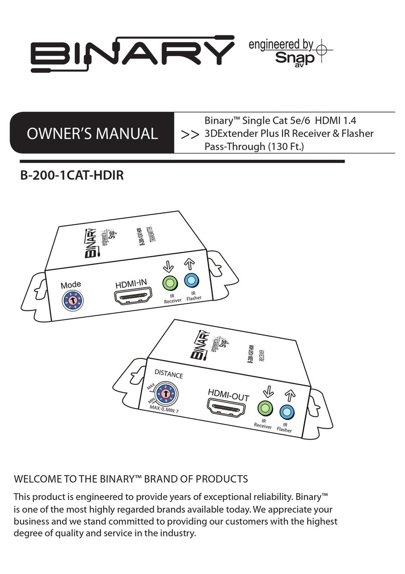
OWNER’S MANUAL >>Extender For HDMI™ Cables
IMPORTANT SAFETY INSTRUCTIONS
SET UP GUIDE FOR MODELS:
HD-1CAT-1080P-130
HD-1CAT-1080P-50
HD-2CAT-1080P-130
SPECIFICATIONS
FREQUENTLY ASKED QUESTIONS
WARRANTY INFORMATION
CAT-5
HDCP COMPLIANT
TRANSMITTER
HD-1CAT-1080P-130 HD-1CAT-1080P-50 HD-2CAT-1080P-130
CONGRATULATIONS!
ON SELECTING THIS BINARY™ BRAND PRODUCT
This product is designed to provide years of exceptional reliability. Binary™ is one of the most highly regarded
brands available today. We appreciate your business and we stand committed to providing our customers with
the highest degree of quality and service in the industry.
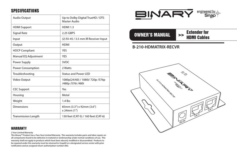
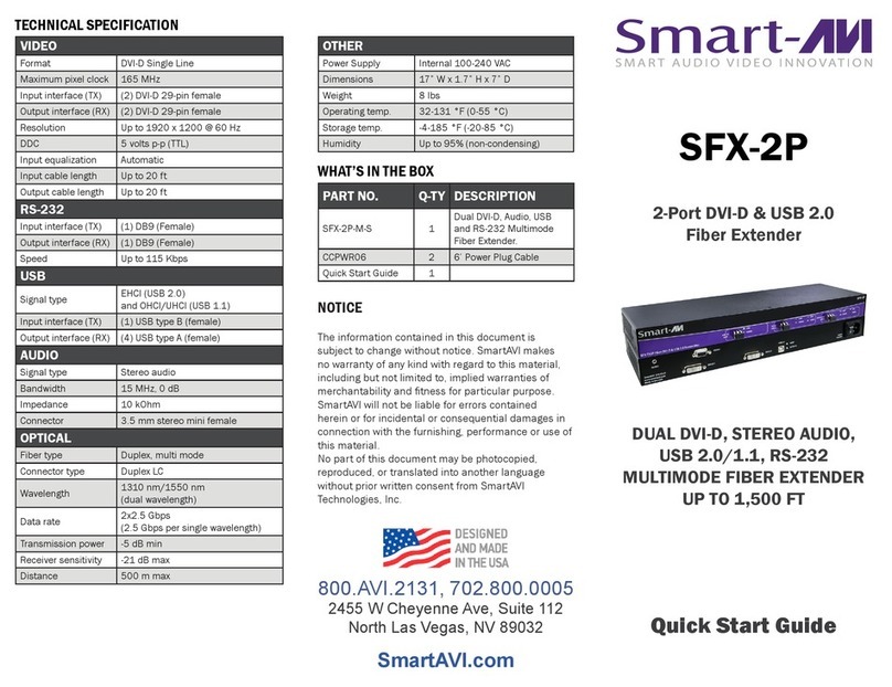
TECHNICAL SPECIFICATIONS HD-1CAT-1080P-130 HD-1CAT-1080P-50 HD-2CAT-1080P-130
Audio Output Stereo or 7.1 Channel Surround Up to 7.1 Channel Surround
HDMI™ Support HDMI™ 1.2 HDMI™ 1.3A
Video Bandwidth 4.95 GBPS 6.75 GBPS
Input
Output
1080iS1080p
Cat 5 50M (164 ft) 40M (130 ft)
Cat 6 60M (197 ft) 50M (164 ft)
1080iS1080p
Cat 5 25M (82 ft) 15M (50 ft)
Cat 6 30M (98 ft) 20M (65 ft)
1080iS1080p
Cat 5 55M (180 ft) 40M (130 ft)
Cat 6 60M (197 ft) 50M (164 ft)
Transmitter Receiver
(1) HDMI™ (1) RJ-45
Transmitter Receiver
(1) RJ-45 (1) HDMI™
Transmitter Receiver
(2) RJ-45 (1) HDMI™
Transmitter Receiver
(1) HDMI™ (2) RJ-45
TECHNICAL SPECIFICATIONS HD-1CAT-1080P-130 HD-1CAT-1080P-50 HD-2CAT-1080P-130
Housing Metal Metal (TX), Plastic (RX) Metal
Product Weight 0.77 lbs. 0.43 lbs. 0.70 lbs.
Dimensions Transmitter & Receiver: 85mm
(3.3”) x 92mm (3.6”) x 24mm (.94”)
Transmitter: 85mm (3.3”) x 92mm
(3.6”) x 24mm (.94”)
Mini Receiver: 35mm (1.4”) x
24mm (0.9”) x 22mm (0.9”)
Transmitter & Receiver: 85mm
(3.3”) x 92mm (3.6”) x 24mm (.94”)
Transmission Length
HDCP Compliant YES
8 Level Digital Equalization YES
Power Supply 5V 4A DC
Input TMDS Signal 1.2 Volts (Peak to Peak)
Input DDC Signal 5 Volts (Peak to Peak)
Power Consumption 2 Watts (Max)
HDMI™ Connector 19 Pin Female
RJ-45 Connector 2 Indication LEDs
Video Output 480i / 480p / 720p / 1080i / 1080p
Binary Cables
10405 Granite Street
Charlotte, NC 28273
Tech Support:
1-866-838-5052
©2009 Binary Cables • Charlotte, NC
3-Year Limited Warranty
This Binary™ Product has a 3-Year Limited Warranty. This warranty includes parts and
labor repairs on all components found to be defective in material or workmanship under
normal conditions of use. This warranty shall not apply to products which have been
abused, modied or disassembled. Products to be repaired under this warranty must be
returned to Binary Cables or a designated service center with prior notication and an
assignment return authorization number (RA).
Frequently Asked Questions:
1. How does equalizer (EQ) work? Equalizer is a built-in electronic device used to ne-tune picture quality. Please turn rotary controller
counterclockwise from 7 to 0 to get the optimal vision. If you nd the display is not showing properly, please check your cable connection
and then conrm you are within the maximum transmission limit.
2. What kind of LAN cable is recommended? The transmission length is largely inuenced by the type of LAN cables, the type of A/V
sources, and the type of A/V display. The testing result shows solid LAN cables (usually in 300m/1000ft form) can transmit HDMI™
signals a lot longer than stranded LAN cables (usually in patch cord form). Shielded STP cables perform better than unshielded UTP
cables. A solid UTP CAT 5e cable shows longer transmission length than stranded STP CAT 6 cable. For long extension users, solid
cables are the only choice.
3. I want HDMI™ extension length over stated specication, is that possible? Yes. To extend HDMI™ signals above stated
specication, please use high quality HDMI™ cable (24 gauges) and CAT 6 solid STP cable. If longer extension is required, please set
HDMI™ source at lower resolutions.
4. I am using HD-1CAT-1080P-50 to receive HDMI™ signal, but there is no image on display. HD-1CAT-1080P-50 is only intended to
use for shorter extension length without extra power. The maximum extension length is at 15m under 1080p, or 25m under 720p, or 1080i
resolution. If required application exceeds this extension limit, please use HD-1CAT-1080p-130.
5. There is no image and/or audio on HD display, what could be the problem? First, please check all cables are properly installed.
Second, please check A/V source is functioning correctly. Third, please adjust EQ and turn mode to stereo audio.
6. It is still not working. If the problem persists, please follow the EDID learning instruction stated below to learn specic EDID information
from your HD display. Then, repeat the sequences stated in previous question.
EDID Learning Instructions, ONLY FOR: HD-1CAT-1080P-130 and HD-1CAT-1080P-50
1. Turn on the transmitting end of the unit.
2. Turn the mode counterclockwise from number 0 (for 5.1 channel and 7.1 channel) or number 1 (for stereo) until you reach number 7.
3. Use an HDMI™ cable to connect the unit to the display (not the video source). The LED on the RJ-45 will dim and light again, which
indicates the EDID learning is nished.
4. Turn the mode clockwise from number 7 to number 0 (for 5.1 channel and 7.1 channel) or number 1 (for stereo). The most important
thing is not to turn the rotary arrow past 6, which will erase the EDID just learned and restore the factory default EDID.
5. Reconnect the unit as dened in the Installation Instructions.
SPECIFICATIONS
™
Rev 090624
IMPORTANT SAFETY INSTRUCTIONS
WARNING:To reduce the risk of re or electric shock, do not expose this apparatus to water!
1. Read these instructions.
2. Keep these instructions.
3. Heed all warnings.
4. Follow all instructions.
5. Do not use this apparatus near water.
6. Clean only with a dry cloth.
7. Do not block any ventilation openings. Install according to manufacturer’s instructions.
8. Do not install near any heat sources such as radiators, heat registers, stoves or other apparatus (including ampliers) that
produce heat.
9. Do not override the safety purpose of the polarized or grounding-type plug. A polarized plug has two blades - one wider than
the other. If the provided plug does not t into your outlet, consult an electrician for replacement of the obsolete outlet.
10.Protect the power cord from being walked on or pinched particularly at plug, convenience receptacles, and the point where
it exits from the apparatus.
11.Only use attachments/accessories specied by the manufacturer.
12.Unplug this apparatus during lightning storms or when unused for long periods of time.
13.Refer all servicing to qualied service personnel. Servicing is required when the apparatus has been damaged in any way,
such as when the power-supply cord or plug is damaged, liquid has been spilled or objects have fallen into the apparatus,
the apparatus has been exposed to rain or moisture, does not operate normally, or has been dropped.
14.Do not expose this equipment to dripping or splashing and ensure that no objects lled with liquids, such as vases, are
placed on the equipment.
15.To completely disconnect this equipment from the AC mains, disconnect the power supply cord plug from the AC receptacle.
Installation Instructions
1. Test all associated equipment and cables in the system for proper operation. Turn off all power before proceeding.
2. Make sure the HDMI™ cables being used do not exceed 1.0M (3.28 ft) and are at least 26 AWG. Any length longer than this may cause
intermittence issues. To ensure maximum performance, please use high quality HDMI™ cables capable of transmitting 1080p signals.
3. Determine the best placement of the unit based on how it will be incorporated into the system design. Leave enough room to reach the EQ
adjustment after installation.
4. Determine the correct Mode to set the transmitter (see Mode Chart above).
5. Make sure all CAT 5 or CAT 6 cables are properly terminated (we recommend EIA/TIA-568B) and connected as shown in the diagram above.
6. Connect the HDMI™ cables as shown in the diagram above.
7. Turn on all associated equipment, plug in the 5V DC power, and verify that the signal LEDs are illuminated.
8. If a ickering, blinking, or snowy image is seen, adjust the EQ dial to improve the cable signal. An EQ set to zero “0” stands for the
strongest signal for longer cable lengths, while 7 is for short cable lengths. Try adjusting the EQ from 7 to 0 until picture is clear.
9. Once you have a picture, turn clockwise towards 7 until you no longer have a picture; adjust counterclockwise until picture
comes back. This will ensure you have reached the optimal setting.
SET UP GUIDE FOR:
HD-1CAT-1080P-130
PACKAGE CONTENTS
(1) Transmitter
(1) Receiver
(2) In-line Transformers
(1) Product Manual
(8) Rubber Feet
(4) Black Screws
MODE CHART
0 = HDMI™ mode with surround sound audio output
1 = HDM™ mode with stereo audio output
2 = DVI mode
3-5 = Not used
6 = Use default EDID (Extended Display
Identication Data)
7 = Learn EDID from the display
HDMI-OUT
EQ
N
HDMI-I
Mode
TRANSMITTER
RECEIVER
Installation Instructions
1. Test all associated equipment and cables in the system for proper operation. Turn off all power before proceeding.
2. Make sure the HDMI™ cables being used do not exceed 1.0M (3.28 ft) and are at least 26 AWG. Any length longer than this may cause
intermittence issues. To ensure maximum performance, please use high quality HDMI™ cables capable of transmitting 1080p signals.
3. Determine the best placement of the unit based on how it will be incorporated into the system design. Leave enough room to reach the EQ
adjustment after installation.
4. Make sure all CAT 5 or CAT 6 cables are properly terminated (we recommend EIA/TIA-568B) and connected as shown in the diagram above.
5. Connect the HDMI™ cables as shown in the diagram above.
6. Turn on all associated equipment, plug in the 5V DC power, and verify that the signal LEDs are illuminated.
7. If a ickering, blinking, or snowy image is seen, adjust the EQ dial to improve the cable signal. An EQ set to zero “0” stands for the strongest signal
for longer cable lengths while 7 is for short cable lengths. Try adjusting the EQ from 7 to 0 until picture is clear.
8. Once you have a picture, turn clockwise towards 7 until you no longer have a picture; adjust counter clockwise until picture comes back. This will
ensure you have reached the optimal setting.
Installation Instructions
1. Test all associated equipment and cables in the system for proper operation. Turn off all power before proceeding.
2. Make sure the HDMI™ cable being used does not exceed 1.0M (3.28 ft) and are at least 26 AWG. Any length longer than this may cause
intermittence issues. To ensure maximum performance, please use high quality HDMI™ cables capable of transmitting 1080p signals.
3. Determine the correct Mode to set the transmitter (see Mode Chart above).
4. Make sure all CAT 5 or CAT 6 cables are properly terminated (we recommend EIA/TIA-568B) and connected as shown in the diagram above.
5. Connect the HDMI™ cable as shown in the diagram above .
6.Turn on all associated equipment, plug in the 5V DC power, and verify that the signal LEDs are illuminated.
NOTE: To ensure maximum
performance please use high
quality HDMI cables capable of
transmitting 1080p signals.
SET UP GUIDE FOR:
HD-2CAT-1080P-130
SET UP GUIDE FOR:
HD-1CAT-1080P-50
N
HDMI-I
Mode
TRANSMITTER
RECEIVER
HD Source
TV
HDMI-OUT
EQ
N
HDMI-I
TRANSMITTER
RECEIVER
TMDS
DDC
+5V DC
PACKAGE CONTENTS
(1) Transmitter
(1) Receiver
(1) In-line Transformers
(1) Product Manual
(4) Rubber Feet
(2) Black Screws
PACKAGE CONTENTS
(1) Transmitter
(1) Receiver
(1) In-line Transformers
(1) Product Manual
(8) Rubber Feet
(4) Black Screws
MODE CHART
0 = HDMI™ mode with surround sound audio output
1 = HDMI™ mode with stereo audio output
2 = DVI mode
3-5 = Not used
6 = Use default EDID (Extended Display
Identication Data)
7 = Learn EDID from the display
™
™
™
™
™
+5V DC
CAT -5/5e/6
TRANSMITTER
RJ45-OUT
CAT-5/5e/6
TRANSMITTER
CA T -5/5e/6
RECEIVER
+5V DC
+5V DC
CA T -5/5e/6
RECEIVER
CAT-5/5e/6
TRANSMITTER
RJ45-OUT
RJ45-IN
RJ45-OUT
-IN

This manual suits for next models

2

Other Binary Extender manuals

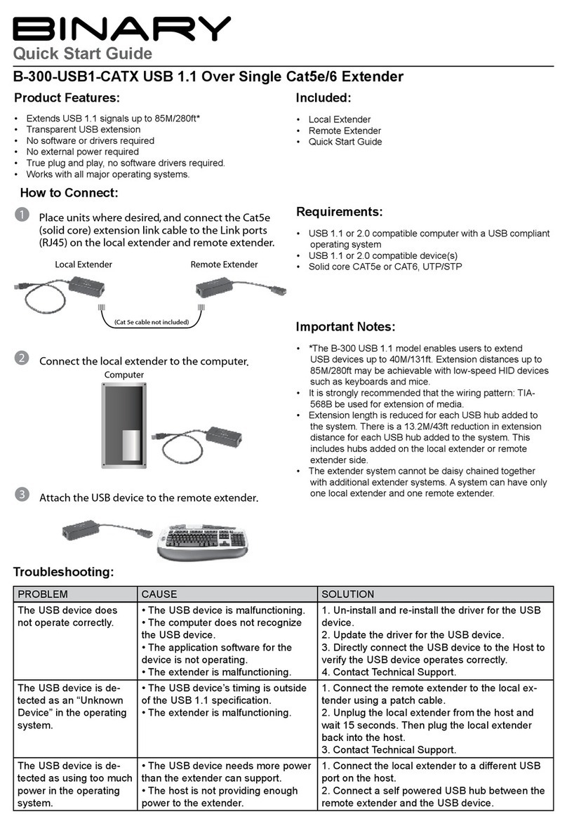
Binary B-300-USB1-CATX User manual

Binary

Binary B-300-USB1-CATX User manual

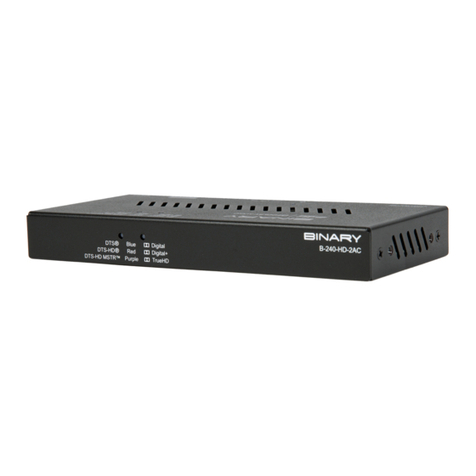
Binary B-240-HD-2AC User manual

Binary

Binary B-240-HD-2AC User manual

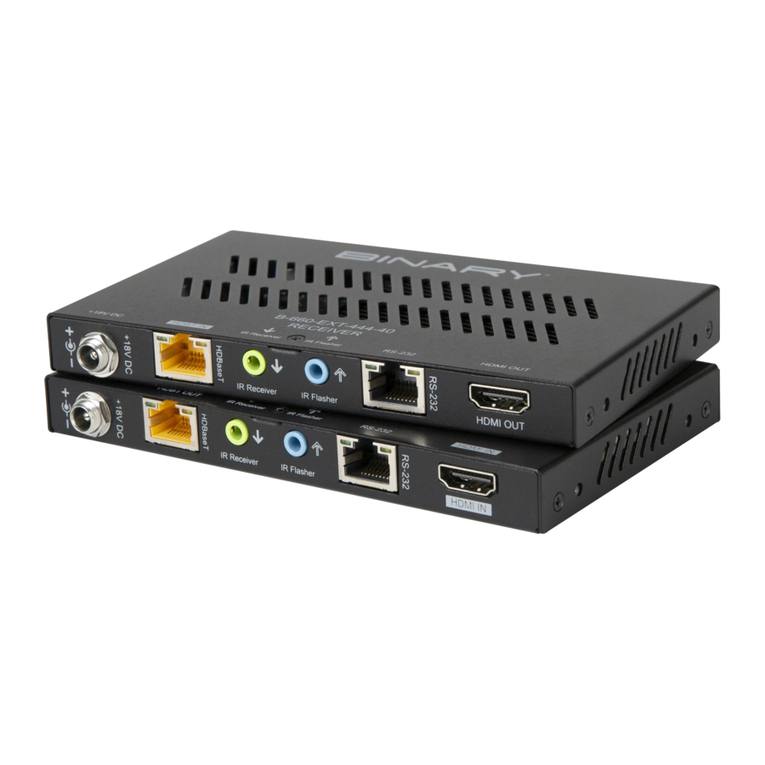
Binary B-660-EXT-444-40 User manual

Binary

Binary B-660-EXT-444-40 User manual

Binary Binary 360 Series User manual

Binary

Binary Binary 360 Series User manual

Binary B-200-1CAT-HDIR User manual

Binary

Binary B-200-1CAT-HDIR User manual

Binary B-350-USB2-CATX User manual

Binary

Binary B-350-USB2-CATX User manual

Binary B-660-EXT-444-100AS User manual

Binary

Binary B-660-EXT-444-100AS User manual

Binary B760-EXT-444-300 User manual

Binary

Binary B760-EXT-444-300 User manual

Binary B-220-1CAT-VGA-A User manual

Binary

Binary B-220-1CAT-VGA-A User manual

Binary B-210-HDMATRIX-RECVR User manual

Binary

Binary B-210-HDMATRIX-RECVR User manual

Binary B-320-1CAT-HDIR User manual

Binary

Binary B-320-1CAT-HDIR User manual

Binary HD-2CAT-1080P-130 User manual

Binary

Binary HD-2CAT-1080P-130 User manual

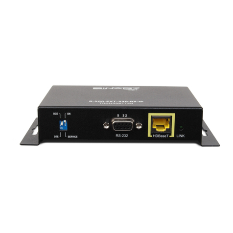
Binary B-500-EXT-330-RS-IP User manual

Binary

Binary B-500-EXT-330-RS-IP User manual

Binary B-300-HDMATRIX-RCVR User manual

Binary

Binary B-300-HDMATRIX-RCVR User manual

Binary B-200-1CAT-VGA User manual

Binary

Binary B-200-1CAT-VGA User manual

Binary B-300-USB2-CATX User manual

Binary

Binary B-300-USB2-CATX User manual

Binary 330 Series User manual

Binary

Binary 330 Series User manual

Binary B-520-EXT-230-RS-W User manual

Binary

Binary B-520-EXT-230-RS-W User manual

Binary B-320-HDMATRIX-RCV-W User manual

Binary

Binary B-320-HDMATRIX-RCV-W User manual

Binary B-320-1CAT-HDIR-W User manual

Binary

Binary B-320-1CAT-HDIR-W User manual

Binary B-400-1COAX-HDIR User manual

Binary

Binary B-400-1COAX-HDIR User manual

Binary B-520-TX-230-IR User manual

Binary

Binary B-520-TX-230-IR User manual

Binary B-560-EXT-444-70 User manual

Binary

Binary B-560-EXT-444-70 User manual

Binary B-520-EXT-330-RS-IP User manual

Binary

Binary B-520-EXT-330-RS-IP User manual

Popular Extender manuals by other brands

Extron electronics USB Extender Plus Series user guide

Extron electronics

Extron electronics USB Extender Plus Series user guide

Nexa LEST-701 operating manual

Nexa

Nexa LEST-701 operating manual

serverLink SL-KX-300 Quick installation guide

serverLink

serverLink SL-KX-300 Quick installation guide

VDO360 Springline 3.0 user manual

VDO360

VDO360 Springline 3.0 user manual

Wilson Electronics 460054 installation guide

Wilson Electronics

Wilson Electronics 460054 installation guide

SY HDBT-60T installation guide

SY

SY HDBT-60T installation guide

Appsys ProAudio ADX-16 user manual

Appsys ProAudio

Appsys ProAudio ADX-16 user manual

ADTRAN T200 FNID Installation and Maintenance
ADTRAN

ADTRAN T200 FNID Installation and Maintenance

TP-Link TL-WA854RE Quick installation guide

TP-Link

TP-Link TL-WA854RE Quick installation guide

Maxim Integrated Icron Starling 3251C-10-PL quick start guide

Maxim Integrated

Maxim Integrated Icron Starling 3251C-10-PL quick start guide

Rose electronics Crystal View Installation and operation manual

Rose electronics

Rose electronics Crystal View Installation and operation manual

EnGenius ERB9250 user manual

EnGenius

EnGenius ERB9250 user manual

Z-Wave ZXT-120 user manual

Z-Wave

Z-Wave ZXT-120 user manual

G&D VISIONXS-F-DP-UHR Series Installation & operation

G&D

G&D VISIONXS-F-DP-UHR Series Installation & operation

Multidyne Electronics DVI-6000 FTX instruction manual

Multidyne Electronics

Multidyne Electronics DVI-6000 FTX instruction manual

Network Technologies XTENDEX ST-C6USBH-300 operating manual

Network Technologies

Network Technologies XTENDEX ST-C6USBH-300 operating manual

Siemens SIMATIC NET SCALANCE XM-400 operating instructions

Siemens

Siemens SIMATIC NET SCALANCE XM-400 operating instructions

Positron BRX-XLR user guide

Positron

Positron BRX-XLR user guide

manuals.online logo
manuals.online logoBrands
  • About & Mission
  • Contact us
  • Privacy Policy
  • Terms and Conditions

Copyright 2025 Manuals.Online. All Rights Reserved.