EDLUND 625T User manual

M102 REV. A (OCT. 2002)
- 1 -
SERVICE MANUAL M102
MODEL # 625T CROWN OPENER

M102 REV. A (OCT. 2002)
- 2 -
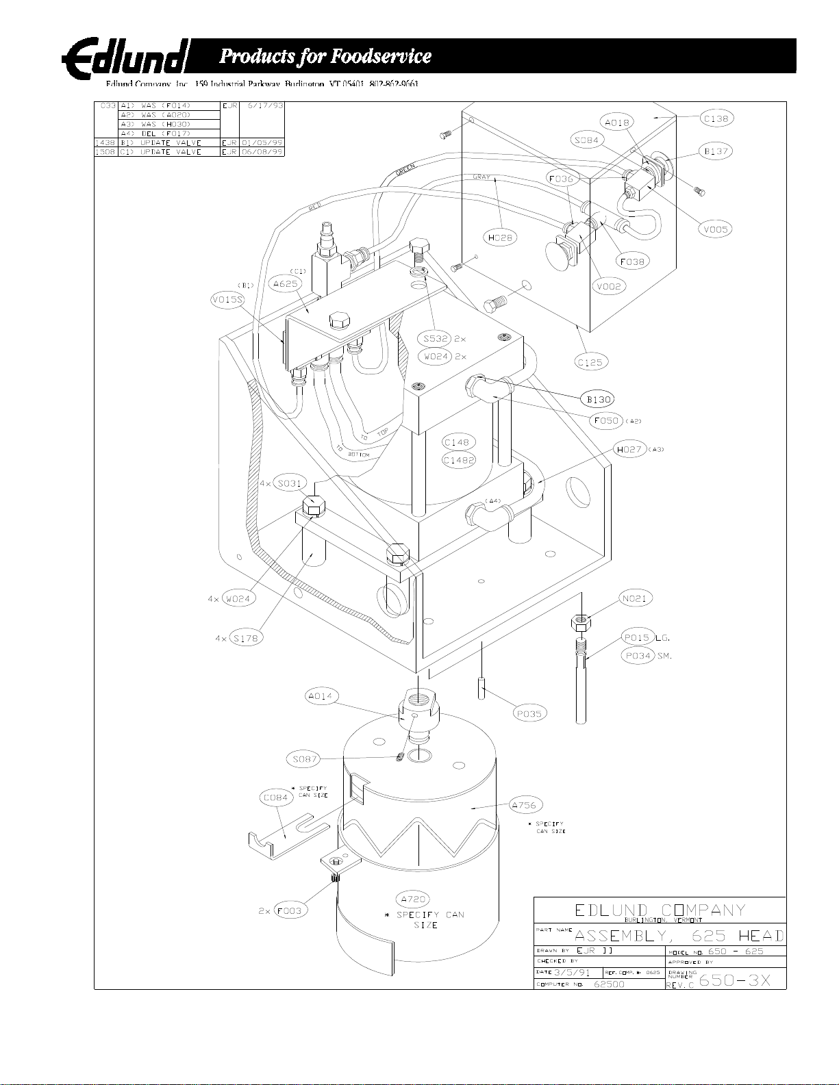
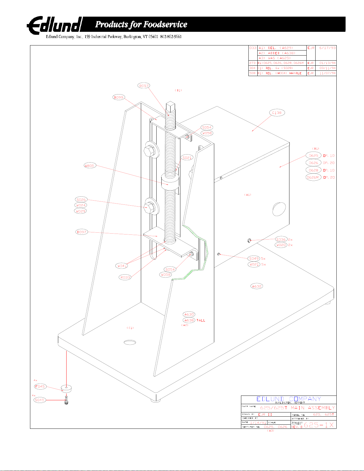
MODEL 625 OPERATING AND ADJUSTING INSTRUCTIONS
The Edlund Model 625 Pneumatic Can Opener operates at a minimum pressure of 75 PSIG. Lubrication is
not necessary but clean, dry air will prolong the units.
The opener may be connected to the air line using the quick disconnect coupling furnished and a length of
air hose.
The opener is simple to operate using the following procedure:
1. Connect air line and set inlet pressure to 75 PSIG minimum.
2. Place can to be opened on base against tab on guard ring. The can will be aligned with can guard
at the top of the opener.
3. Press both red buttons on sides of head at the same time. Hold until cylinder completes its
downward stroke and then release both buttons. Crown punch will retract to its starting position.
4. Remove can and repeat steps 2 and 3 as required.
The Model 625 opener is factory adjusted to open a standard #10 can or the particular size can ordered.
The crown punch should penetrate the can just far enough to cut off the cover but not so far as to cause
excessive splashing of liquid in can. If an adjustment is required to improve operation of the opener, the
following procedure will be used:
CAUTION: To avoid personal injury, disconnect air line before making any adjustment to opener.
1. Disconnect air line to unit.
2. Place can to be opened under can guard.
3. Loosen the four nuts or bolts at the rear of the vertical (see drawing) and raise or lower the head as
desired, keeping the can and can guard aligned and level.
4. Tighten fasteners and close interlock door. Operate according to operating instructions.
If a new size can is required to be opened, the following procedure will be used:
1. Disconnect airline to unit.
2. With one hand, hold up on the knife guard ring and with the other hand unscrew the two thumb
screws. (A flathead screwdriver may be needed to start the screws.) Let the guard ring down and
place to the side. Now hold up on the knife with one hand (being careful of any sharp parts of the
knife), and with the other hand, pull the blade clip straight out. (You may have to wiggle the knife to
loosen the blade clip.) Let the knife down. Place knife and clip with guard ring. Do not let knife fall
in the deck.
3. Install desired crown punch and can guard onto opener.
4. If can knockout pin does not align with holes in crown punch rotate crown punch or remove pin and
use proper size pin in alternate location.
5. Place can to be opened under can guard. If new can is taller than former size can, loosen the four
nuts or bolts at rear of vertical (see drawing) and raise head so can will fit.
6. Place ¼ inch to 5/16-inch thick shim between can and can guard.
7. Level and align head and tighten fasteners at rear of vertical.
8. Operate according to preceding instructions.
The knife, guard and clip should be removed after every use for cleaning. To remove any
preservatives or brine from the unit clean with mild soap and water. For disassembly see #2 above.
The entire machine may be hosed down inside and out.

M102 REV. A (OCT. 2002)
- 3 -
Blade Cleaning and Inspection
1. Disconnect air remove two knurled screws that hold the guard ring in place. It may be
necessary to pull down on the guard ring to remove it, if the locating pins are tight.
2.Support the blade with your hand, lifting slightly to loosen blade clip so it can be pulled out
releasing the blade to drop out.
3. Wash blade, guards ring and clip in dishwasher if desired to sterilize. The rest of the machine
can be washed with soap and water.
4.Check that the knock-out pins are straight and line up with holes in the blade backing plate and
that their mounting screws are tight.
5. Inspect blade for nicks and other damage that may cause metal slivers when opening the can.
Replace or return to the factory for repair if damaged.
6. Reassemble blade, blade clip and all guarding. Be sure all screws are tight. Reconnect air
supply

M102 REV. A (OCT. 2002)
- 4 -
625 Operations and Troubleshooting
Operation Description
1. Place can in position against guard ring tab. There should be approximately 1/8" between the
top of the can and the bottom of the guard ring. Adjust, if necessary, keeping the head level
and spaced evenly.
2. Connect a clean and dry air supply set to about 85 psi pressure.
3. Depress both red buttons at the same time and hold down until blade hits the end of stroke and
release. Lid should be completely separated from the can.
4. After removing the opened can, while holding the can by the sides, put the lid up against the
magnet. Then pull the can down leaving the lid. When the next can is opened, the lid will be
knocked off by a pin which is connected to a small air cylinder.
Pneumatic Description
The two red palm buttons (B138) are attached to one normally open (V005) and one normally
closed 3-way air valve (V002). The output of these two valves is connected to the pilot actuators
of a 5-way valve (V015S). The two outputs of the 5-way valve are connected to a 5" dia. Air
cylinder (C148), which is connected to a blade (A756), which removes the lid. Both buttons must
be actuated to shift the 5-way valve and extend the cylinder and open the can. Releasing them
shifts the 5-way valve back and retracts the air cylinder.

M102 REV. A (OCT. 2002)
- 5 -
Symptom
a. Check air connection and supply pressure (air should come out of unit when it is
disconnected).
b. Remove cover to check valve operation. The valve (V005) connected to the right
button should only let airflow through it when actuated. Remove the side hose by pushing
in collar and pulling out the hose at the same time. Operating the button sh
2. Air leaks out around cylinder shaft near blade. The cover must be removed to pinpoint leaks. Worn seals usually cause cylinder end
leaks and the cylinder must be removed and repaired or replaced.
3. Air leaks out the 5-way valve (V015S) exhaust.
The valve (V015S) probably needs repair or replacing. Remove cylinder top hose to check
if only the valve (V015S) is faulty. If cylinder piston seals are bad, air will come out of the
top cylinder port.
4. Air leaks around one of the valves, V002, V005 or
V015S. Check to be sure all connections are tight and hoses are pushed all the way on. If the
three way valves are stuck or worn out they can leak around the actuating stem.
Disassembly and cleaning is possible but replacement is recommended.
a. V002 valve stuck in and/or
b. V005 valve stuck in and/or
c. V015S valve stuck in open position
d. and/or cylinder seized in down position. Repair or replace factory parts.
a. Inspect blade for damage – replace or return to the factory for reconditioning.
b. To check cylinder stroke, hold both buttons down – blade should come down at least
1-1/2" to the points or 3/8" to the valley. Cylinder may be loose, binding or filled with water
or oil and hydraulically locked, repair or replace as necessary.
c. To adjust the head height – loosen bolts in back and adjust head to correct height or
slightly closer being sure to keep the gap between guard ring and can even on both sides.
d. If the lid is still attached near the front or back, check the gap there, excessive
variation before operation or too much flexing during operation can be caused by a bent
frame or broken welds (be sure knife is good and you have 85 psi of pressur
a. Bent or broken knockout pin. Repair or replace.
b. Damaged blade holding the lid. Repair or replace.
6. Blade fails to open can completely.
7. Lid does not fall out of knife.
Troubleshooting
Only qualified maintenance personnel should do repairs.
1. Unit will not operate when buttons are pushed.
5. Blade goes down, but will not return.

M102 REV. A (OCT. 2002)
- 6 -
PART #
DESCRIPTION
A014
A D A P T O R , 6 2 5 C Y L IN D E R
A018
ADAPTOR,PUSH BUTTON
A625
ASSEMBLY,625 SMC VALVE
A629
W ELDM ENT, #625 HEAD
A630
W ELDMENT,#625 VERTICAL/BASE
A720
W ELDM ENT, #700 G UARD RING , #603 DIA
A756
W E L D M E N T , # 1 0 K N IF E S /S
A805
ASSEM BLY, #625/#825 ADJ NUT
B097
BRACKET,#625 RETAINING
B099
BRACKET,ROD GUIDE
B130
B U S H IN G , R E D U C T IO N , 3 2 2 0 X 8 X 4
B137
BUTTON,RED MUSHROOM PUSH,800T-D6
C084
C L IP , R E T A IN IN G # 1 0 , 6 0 3 S IZ E
C104
CO UPLING , #210-3003, ¼ " FEM ALE
C125
COVER,#625 FRONT
C138
CO VER, #625 TOP
C148
CYLINDER, #625 OPNR 5" BX1 5S S#91-628286
F036
F IT T IN G , ¼ "O D P U S H -IN to 1 /8 N P T M A L E
F038
FITTING, ¼ " Push-in Branch Tee 1/8”
F045
FO OT, #625 M ECH., BLK FI 5200-01-13-5052
F050
F IT T IN G , 3 /8 "O D P U S H -IN E L B O W T O ¼ N P T
H027
HOSE,3/8" OD CLEAR PARFLEX
H028
HOSE,¼" OD CLEAR
H030
HO SE, H101-3/8 ID
K064
KEY, T27 TORX-L (FOR S514)
K065
KEY, T25 TORX-L (FOR S513)
L004
LABEL, #610 “CAUTIO N – DISCO NN”
L005
LABEL, “CAUTION,DUE TO CHEM”
L017
LABEL, BLADE CAUTION
L057
L A B E L , C P L ID C A U T IO N
M 10080
MANUAL,#625 CP INSTR/SERV-TAMPER PROOF
N017
NUT,½-13 S/S HEX
N021
N U T , 3 /8 -1 6 S /S H E X
P015
P IN , K N O C K O U T , 3 /8 X 3 -1 /4 S /S
P034
PIN,SMALL KNOCKOUT/LOCATING
P035
P IN , S /S S M A L L L O C , D O W E L , 3 /1 6 X ½
R033
RING , RETAINING , 5133-50H
R057
ROD,#825 ADJUSTING
S021
S C R E W , 3 /8 -1 6 X 5 /8 S /S F H S
S026
S C R E W , ½ -1 3 X 1 S /S H E X H E A D
S028
S C R E W , ½ -1 3 X 1 -1 /4 S /S H E X H E A D
S031
S C R E W , ½ -1 3 X 2 -1 /2 S /S H E X H E A D
S045
S C R E W , 1 0 -3 2 X ½ S /S H E X H E A D
S084
S C R E W , 8 -3 2 X 5 /1 6 S /S R H M
S093
S C R E W , 1 0 -3 2 X ¼ S O C H D C A P S /S
S178
STANDOFF,#625 CYLINDER
S191
SCREW ,BRASS TIP SET,¼-20 X ¼
S379
S C R E W , 3 /8 -1 6 X ¾ H E X S /S
S513
S C R E W , # 1 0 -3 2 X ½ B U T H D S S T O R X S E C R T
S514
S C R E W , ¼ -2 0 X ½ B U T H D S S T O R X S E C R T
V002
VALVE,3 W AY NO,MJV0-3
V005
VALVE,3 W AY NC, MJV-3
V015S
VALVE,SMC 5-W AY DBL.AIR PILOT
V042
VALVE,¼ NPT BALL,LOCKOUT
V055
VALVE,3-PORT W /LOCK OUT ¼ NPT
W 010
W ASHER,#10 S/S FLAT
W 015
W ASHER,¼ S/S FLAT
W 020
W ASHER,¼" S/S LOCK
W 021
W ASHER, #10 S/S LOCK
W 024
W ASHER,½" S/S LOCK
W 026
W A S H E R , 3 /8 " S /S L O C K
W 029
W ASHER, #610/700 12 GA M O UNTING
W 041
W ASHER, #825 THRUST #TT-1001-1
W 058
W ASHER, 3/8" S/S FLAT
Parts List

M102 REV. A (OCT. 2002)
- 7 -
8"
12"
14"
12"
17"
17"

M102 REV. A (OCT. 2002)
- 8 -
Table of contents
Popular Commercial Food Equipment manuals by other brands

LIVIVO
LIVIVO BS791 Safety and instruction manual

Igloo
Igloo KING EVO instruction manual

UBC
UBC Frost Stream Freeze operating instructions

Diamond
Diamond CT331/D-N Instructions for installation and use

Federal
Federal SSRSP Series Installation & operation instructions

Cambro
Cambro IBSD37 Setup guide and user manual

M-system
M-system Mastro ADA2001 Instructions for installation, use and maintenance

MSW
MSW MSW-FMM-01 user manual

Falcon
Falcon DOMINATOR PLUS E3405 Installation and servicing instructions

Shear Magic
Shear Magic Nifty 2000 instruction manual

LTI
LTI DI-FT Series Operation & maintenance manual

Arneg
Arneg Lisbona Direction for Installation and Use