Please read thoroughly before operation and keep for future reference 9
QTY PART
NUMBER DESCRIPTION
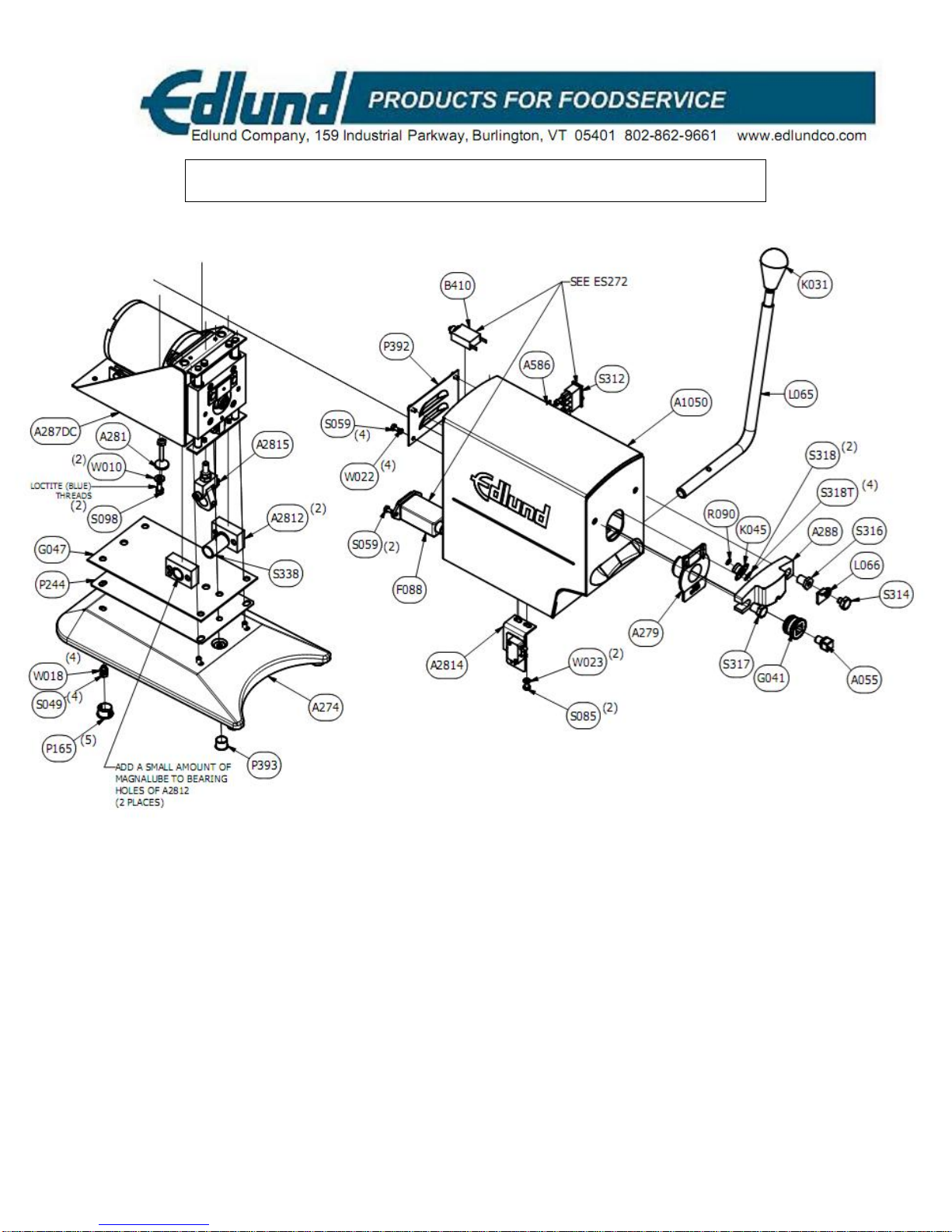
4S049 SCREW, #10-32 X 3/8, SS HEX HEAD
4S059 SCREW, #6-32 X .25, SS HEX HEAD
2S085 SCREW, #8-32 X 1/4 S/S RHM
SLOTTED
2S098 SCREW, #10-32 X 3/8 SHCS, SS
1S312 SWITCH, ROCKER--HI/LOW
1S314 SCREW, KNIFE HOLDER, KH LATCH
SHOULDER
1S316 SCREW, KNIFE HOLDER, RIGHT
SHOULDER
1S317 SCREW, KNIFE HOLDER, LEFT
SHOULDER
1S318 SHIM, SS, 0.005 THK
1S318T SHIM, .015 X .335 X.438
1S338 SPACER, ACTUATOR LEVER
2W010 WASHER, FLAT, #10 SS
4W018 WASHER, #10 LOCK, PLATED
4W022 WASHER, #6 LOCK, SS
2 W023 WASHER, #8 LOCK, SS
270 ASSEMBLY AND PARTS LIST--
115V
QTY PART
NUMBER DESCRIPTION
1A055 ADAPTER, DRIVE GEAR
1A273C WELDMENT, HOUSING
ASSEMBLY
1A274 WELDMENT, BASE
1A279 ASSEMBLY, GEAR SHIELD
1A281 ASSEMBLY, SWITCH ACTUATOR
2A2812 ASSEMBLY, LEVER ARM
BEARING MOUNT
1A2814 ASSEMBLY, ROLLER SWITCH
1A2815 ASSEMBLY, LEVER CAM
1A283DC ASSEMBLY, 270 FRAME,
MOTOR/GEAR TRAIN, 115V
1A288 ASSEMBLY, KNIFE HOLDER
1A586 ASSEMBLY, SPEED CONTROL
DIODES
2A641 ASSEMBLY, CORD W/
CONNECTORS
1B410 BREAKER, THERMAL, 1.2 A
1G041 GEAR, CAN DRIVE
1G047 GASKET, BASE
1K031 KNOB, LEVER ARM
1K045 KNIFE
1L049 LABEL, NSF
1L065 LEVER, ACTUATOR ARM
1L066 LATCH, KNIFEHOLDER
1L073 RATING LABEL, 270, POWER
MOTOR, 115V
1L087 CAUTION LABEL, RED, 270
5P165 PLUG
1P244 PLATE, GASKET
1P392 PLATE, LOUVER COVER
1P393 PLUG