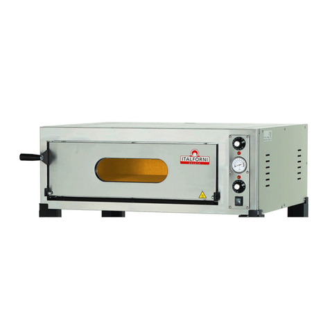
Italforni EGA/LE User manual

PDS/4402/013 05-10-2005
USE AND MAINTENANCE MANUAL
ECO GAS A/B
Category: II2H3+
Construction type: A / B11
0705

Use and maintenance manual
2
INTRODUCTION
This manual contains the necessary instructions
for use and the safety rules to be applied for the
correct operation of the appliance. This manual
must be given to the people in charge of using
the machine and its maintenance.

Use and maintenance manual
3
CONTENTS
CHAP.1 - INTRODUCTION AND OVEN DESCRIPTION
1.1 General warnings
1.2 Technical data plate and supplementary plate
1.3 Technical specifications
CHAP.2 - GENERAL INSTRUCTIONS (for the installer)
2.1 Assembly and installation site
2.2 Gas connection
2.3 Electrical connection
CHAP.3 - COMMISSIONING (for the installer)
3.1 Checking the nominal thermal capacity
3.2 Checking the gas supply pressure
3.3 Conversion to other types of gas
3.4 Instructions for replacing certain components
3.5 Troubleshooting
CHAP.4 - OPERATING INSTRUCTIONS (for the user)
4.1 Commissioning and using the oven
CHAP.5 - CLEANING AND ROUTINE MAINTENANCE
5.1 Wiring diagram

Use and maintenance manual
4
CHAP.1 - INTRODUCTION AND OVEN DESCRIPTION
All gas parts of the appliance are covered by warranty starting from the invoice date.
Any attempt to dismantle, alter or tamper with any part of the appliance shall invalidate the
warranty.
Improper use of the oven as well as any attempt to dismantle or alter it can lead to accidents and
therefore the manufacturer declines all responsibility for any damage to persons or property
caused by tampering. For any faults encountered, contact the nearest authorised service centre or
the manufacturer directly.
The manufacturer declines all responsibility in the following cases:
-Improper use of the oven by unsuitably trained staff.
-Use not complying with the regulations in force in the country of use.
-Lack of or incorrect routine maintenance.
-Use of non-original spare parts.
-Total or partial failure to comply with the instructions.
-Failure to send the warranty certificate.
The electric-gas-powered pizza ovens EGA/LE, EGA/T, EGA/C, EGA/L, EGA/LE2, EGA/T2, EGA/C2,
EGA/L2, EGB/LE, EGB/C, EGB/L, EGB/LE2, EGB/T2, EGB/C2, EGB/L2 all carry the CE symbol issued
by a Notified Body, entrusted with and responsible for assessing compliance with the essential
requisites set out by gas Directive 2009/142/EEC. The oven or the quality of the production system
are subject to periodic monitoring through inspection checks in order to ensure their compliance
with the type of certificate as stated in the above Directive.
The ovens comply with product standards EN 203-1, EN 203-2 and EN 437.
The appliance also complied with the following European Directives:
Low Voltage Directive 73/23/EEC.
Electromagnetic Compatibility Directive 89/336/EEC.
The appliance can be marketed in all European countries whose code is present on the technical
plate. It must be installed in accordance with the rules in force governing the installation of gas-
electric appliances for collective use, with the accessories and the adjustments required by the
country of use as described in the use and maintenance manuals printed in the original and official
languages of the different countries.
In particular, the oven must be installed on a suitable stand or sufficiently stable and fully
horizontal surface in a room with sufficient ventilation and must be used by specialised staff.
Connect a pipe of suitable diameter to the combusted exhaust gas flue collar in order to discharge
the cooking vapours and combustion fumes outside (directly in the flue or using an appropriate
interlocked extractor hood).

Use and maintenance manual
5
The oven is fitted with atmospheric burners located under the refractory racks of the cooking
chamber. The temperature of the chamber is set using an analogue thermostat located on the
control panel. Once the set temperature is reached, the burner will alternate on and off cycles to
maintain this temperature.
If the burner should fail to ignite, a red warning light turns on and then ignition can be attempted
again by pressing the reset button. In the event of excessive or irregular heating of the cooking
chamber, a safety thermostat is triggered which blocks the flow of gas and turns the oven off; this
can only be reset manually.
1.1 –General warnings
Read this manually carefully as it provides safety instructions for use and maintenance. The
purpose of this manual is to make operators aware of the rules and essential criteria to ensure
their safety and extend the oven’s service life. This manual must be read by all staff authorised
to work on the appliance before its commissioning.
This instruction manual must be keep with the oven for future reference. If the oven is sold or
transferred, make sure that the manual always accompanies it, so that the new user can be
informed about its operation and the safety warnings. It must be kept in a safe and dry place
that can be quickly located whenever it needs to be referred to. If it damaged or lost, contact
the manufacturer directly for a replacement copy. For any doubts, contact your nearest service
centre or the manufacturer directly.
Put the appliance into service in accordance with the regulations in force. These instructions
only apply to category II2H3+ pizza oven models.
This oven is intended for the following use: cooking pizzas or similar foods. It must not be used
for other purposes; any other use is considered improper. The appliance is intended for
collective and professional use and must be operated by trained staff.
Servicing, conversion to other types of gas, installation and operational checks must only be
performed by qualified staff.
Each time a new part is fitted or a component is adjusted, make sure that it is sealed with paint
to discourage any tampering.
It is advisable to take out a maintenance contract.

Use and maintenance manual
6
For all repairs, contact an authorised service centre and always request original spare parts.
The following symbol denotes “hot surface”. Avoid all direct contact with these surfaces.
1.2 –Technical data plate and supplementary plate
The technical data plate (Fig 1) is located at the rear of the oven and contains the voltage rating
and all the other information necessary for installation. The supplementary plate (Fig. 2) states the
basic rules to be followed for correct installation.
Fig. 1
Fig. 2

Use and maintenance manual
7
1.3 –Technical specifications
Table 1
Model
EGA/LE
EGA/L
EGA/C
EGA/T
EGA/LE2
EGA/L2
EGA/C2
EGA/T2
External dimensions L x D
x H
960 x 935 x 520
mm
960 x 935 x 985
mm
Base height
700 mm
/
700 mm
/
Total nominal thermal
capacity
14 kW
28 kW
Electrical power rating
25 W
50 W
Gas connection
1 / 2 “ - ISO 7-1
Exhaust fumes flue
Ø 120 mm; minimum length ≥ 500 mm
Appliance category
II2H3+
Type of construction
A
B11
Electrical power supply
220-230 V ~ 50 Hz
Power cable
Type H05RN-F 3x1.5 mm2
Gas supply pressure
Liquid butane/propane gas
G30/G31
Methane gas G20
: 30/37 mbar
: 20 mbar
Gas consumption
calculated with calorific
value below Hiat 15° and
1013 mbar:
G 30/G 31: 1.10 kg /h
G 20 : 1.48 m3/ h
G 30/G 31: 2.20 kg /h
G 20 : 2.96 m3/ h
Main injector diameter
G 30 / G 31 : 195 1/100 mm
G 20 : 355 1/100 mm
Primary air bushing setting
G 30 / G 31 : 41 mm
G 20 : 16 mm

Use and maintenance manual
8
Model EGA
Model EGA/2

Use and maintenance manual
9
Model
EGB/LE
EGB/L
EGB/C
EGB/T
EGB/LE2
EGB/L2
EGB/C2
EGB/T2
External dimensions L x D x
H
960 x 1235 x 520
mm
960 x 1235 x 985
mm
Base height
700 mm
/
700 mm
/
Total nominal thermal
capacity
19 kW
38 kW
Electrical power rating
25 W
50 W
Gas connection
1 / 2 “ - ISO 7-1
Exhaust fumes flue
Ø 120 mm; minimum length ≥ 500 mm
Appliance category
II2H3+
Type of construction
B11
Electrical power supply
220-230 V ~ 50 Hz
Power cable
Type H05RN-F 3x1.5 mm2
Gas supply pressure
Liquid butane/propane
gas G30/G31
Methane gas G20
: 30/37 mbar
: 20 mbar
Gas consumption calculated
with calorific value below Hi
at 15° and 1013 mbar:
G 30/G 31: 1.50 kg / h
G 20 : 2.01 m3/ h
G 30/G 31: 3.00 kg / h
G 20 : 4.02 m3/ h
Main injector diameter
G 30 / G 31: 230 1/100 mm
G 20: 410 1/100 mm
Primary air bushing setting
G 30 / G 31 : 41 mm
G 20 : 16 mm

Use and maintenance manual
10
Model EGB/2
Model EGB

Use and maintenance manual
11
CHAP.2 –GENERAL INSTRUCTIONS (for the installer)
2.1 - Assembly and installation site
Upon receiving the oven and before proceeding with installation check that the goods supplied
correspond to the order specifications and that no damage has been caused during transport; in
the event of damage or missing parts, immediately inform the carrier or the manufacturer
providing the necessary details.
The installer must make sure that commissioning is carried out in accordance with the rules in
force in the country where the oven is used. The installer must be in possession of the necessary
professional qualifications and must follow the safety rules scrupulously. All special maintenance
procedures (any conversion to other types of gas or parts replacement) must be carried out by
qualified staff authorised by the manufacturer.
The oven must be installed in a well ventilated room with permanent ventilation openings
ensuring a sufficient flow of combustion air and a healthy workplace in general; the ovens are
classified as type B11 and the combustion fumes must therefore be discharged outside the
installation premises. The ovens are fitted with a windproof device incorporated into the exhaust
circuit in the event of a flue obstruction or abnormal draught. Connect a straight section of pipe no
less than 500 mm in length to the flue collar and then connect the pipe to the flue of the building
making sure it draws properly (Fig. 4a); alternatively, if possible, place the oven under an extractor
hood with a system interlocked to the gas supply circuit which can ensure complete extraction of
the combusted gases generated during cooking (Fig. 4b).
The ovens of the ECO GAS A and ECO GAS B series must be installed in well-ventilated rooms with
permanent ventilation openings ensuring a sufficient flow of combustion air and a healthy
workplace in general to protect the health of the operators and ensure the proper operation of
the appliances.
The single oven of the ECO GAS A series (14 kW of thermal capacity) is classified as type A,
therefore it is not mandatory to connect it directly to a flue or to a device (hood) to discharge the
combustion fumes outside. In order to ensure the safety and hygiene of the workplace in terms of
concentrations of harmful substances produced by combustion and cooking, the room must be
equipped with mechanical devices, such as wall fans, in order to promote ventilation and fresh air
circulation.

Use and maintenance manual
12
The single oven of the ECO GAS B series (19 kW of thermal capacity) is classified as type B11 and
the combustion fumes must therefore be discharged outside the installation premises. Both series
of ovens are fitted with a windproof device incorporated into the exhaust circuit in the event of a
flue obstruction or abnormal draught. Connect a straight section of pipe no less than 500 mm in
length to the flue collar and then connect the pipe to the flue of the building making sure it draws
properly (Fig. 4a); alternatively, if possible, place the oven under an extractor hood with a system
interlocked to the gas supply circuit which can ensure complete extraction of the combusted gases
generated during cooking (Fig. 4b).
Both series of ovens require a straight section of pipe no less than 500 mm in length and with Ø
120 mm diameter for optimal draught.
The oven should be positioned fully horizontally on the stand or on a stable structure, at a
distance of no less than 100 mm from the left side wall and 500 mm from the right side and rear
wall in order to ensure access for maintenance and cleaning; the oven must not be located near
flammable walls and is not suitable for installation in series. For compliance of the premises
intended to accommodate collective catering systems (volumes, ventilation, smoke exhaust, gas
supply), refer to UNI –CIG safety standards 7722-7723-8723 in their most updated versions and
Italian Ministerial Decree of 12 April 1996 with the subsequent updates. Make sure that the
volume of air needed for combustion is in no way obstructed by objects placed under or around
the appliance, in particular the side holes and slits.
For countries other than Italy, comply with the provisions of national laws and regulations
regarding the installation of gas appliances.

Use and maintenance manual
13
Min.500mm
R
Min.500mm
Min.500mm
Min.500mm
R
V
C
Fig. 4a
Fig. 4b
Key:
C = Interlocked extractor hood
R = Stop cock upstream of the oven
V = Hood cut off valve

Use and maintenance manual
14
2.2 –Gas connection
Before installation, make sure that the oven is designed for use with the gas available. Otherwise,
refer to the paragraph “Conversion to other types of gas” or contact the manufacturer’s service
centre. The connection to the gas supply must be performed in compliance with the specific
installation rules by means of a rigid or flexible pipe made of metal only, with diameters in
proportion to the appliance’s power rating and to the required length. Make sure that the pipe is
not installed near hot areas and that it is not twisted or stretched. Between the gas supply and
every single oven, fit a type approved shut-off cock in a position that is easy to access for opening
and closing. Once the appliance is installed, carry out a seal test on the entire gas circuit, using a
spray for leaks or other non-corrosive foaming substances (do not use flames for this operation).
The joints of the copper pipes must be made using mechanical couplings without gaskets.
The oven is equipped with a type 1 / 2“ ISO 7-1 gas connector.
2.3 –Electrical connection
Connection to the electrical power supply must be carried out in compliance with the regulations
in force. Before performing the electrical connection make sure that the voltage and frequency
shown on the technical data plate are the same as those of the power supply system. The power
cable must be flexible, with characteristics of no less than the type with H05RN-F polychloroprene
rubber insulation. The cable must be connected to the terminal block according to the wiring
diagram enclosed with the appliance, and then secured with a cable clamp.
The wiring pattern is the following:
Yellow/green wire earth
Blue wire neutral N
Brown wire live L
In the event of permanent connection to the mains power supply, a single-pole safety switch of
suitable capacity with a contact opening distance of at least 3 mm must be fitted upstream of the
appliance.
Make sure that the power cable does not come into contact with the flue.
If the plug continues to spark during ignition, even if the burner is working, swap the live wire with
the neutral.
It is essential for the appliance to be properly earthed and included in an equipotential system;
this connection is carried out with the stop screw marked by the symbol located behind the
appliance. The equipotential wire must have a cross-section of at least 10 mm2.
If appliances are installed one on top of the other, each of them must be equipped with an
equipotential system.

Use and maintenance manual
15
CHAP.3 –COMMISSIONING
3.1 –Checking the nominal thermal capacity
The nominal thermal capacity must be checked by the authorised engineer or by the competent
Body, according to the information contained in this user manual. This check must be made for
new installations or for conversions to other types of gas and after all special maintenance
procedures.
There is no way of setting the nominal thermal capacity other than measuring the correct supply
pressure and checking that the injectors used are the correct ones. The sealed (for example with
paint) components must never be tampered with. The nominal thermal capacity is checked using a
counter and a chronometer. The exact volume of gas that must flow for each unit of time can be
found in the technical specifications table. This value must be kept within the required range, with
a tolerance of 5 %.
If any deviations are found, check that injectors of the correct size have been fitted.
3.2 –Checking the gas supply pressure
Before putting the oven into service, check to see whether it is suitable for the category and type
of gas available, as stated on the technical data plate. Otherwise, refer to the paragraph
“Conversion to other types of gas”.
The gas supply pressure is measured, with the appliance in operation, using a pressure gauge for
liquids (for example a “U “ type pressure gauge with minimum 0.1 mbar resolution). To carry out
this check, access the gas solenoid valve by removing the right side panel from the oven; then,
using hoses, connect the pressure gauge “E “ to the incoming and outgoing pressure points “ V “
and “ X “ of the gas solenoid valve after removing the relative fixing screws “ U “ and “ Z “ (see
Fig 5).
Measure the incoming pressure: if this is not within the range of values shown in table 2, the oven
must not be put into operation under any circumstances. The gas supply company must be
informed.

Use and maintenance manual
16
Table 2
Type of gas
Incoming gas pressure (mbar)
Normal
Minimum
Maximum
Methane gas G20
20
17
25
Liquid gas G30/G31
30/37
20/25
35/45
The outgoing pressure must be checked and, if necessary, corrected using pressure regulator “ T “
located on the solenoid valve. After removing the screw cap “ S “, turn the regulator screw “ T “
according to the type of gas by following the instructions in table 3.
Table 3
Type of gas
Outgoing gas
pressure [mbar]
Procedure to be followed
Methane gas G20
9
Adjust the screw “T” until the value stated opposite is
reached.
Liquid gas G30/G31
28/35
Disable the pressure regulator by fully tightening the
screw “T” and check the values stated opposite are
reached.
mmH2O
300
800
500
600
400
700
1100
900
1000
E
Pressione
V
U
S
Z
X
T
Fig. 5
Key:
E = “U” type pressure gauge
U-Z = Fixing screws
V-X = Solenoid valve pressure points
S = Pressure regulator screw cap
T = Pressure regulator screw

Use and maintenance manual
17
After measuring the gas supply pressure, turn the oven off, close the gas cock located upstream
and remove the pressure gauge hoses from the pressure points. Tighten the fixing screws in the
pressure points, tighten the regulator screw cap and seal it with paint to discourage any
tampering.
3.3 –Conversion to other types of gas
If any spare parts are needed, contact the manufacturer’s service centre. The conversion must be
carried out by qualified staff. Referring to the technical specifications in table 4, replace the main
injector and adjust the primary air through the relative bushing.
WARNING - Carry out this operation only after closing the gas shut-off cock located upstream of
the oven and disconnecting the oven from the electrical power supply. Check that the diameter of
the injector is stamped on it in 1/100 of a mm.
Perform the following operations in sequence:
To access the devices to be adjusted and replaced, remove the oven’s front panel.
With a suitable tool, undo and replace the injector “U“ with the correct one for the gas supply.
Undo the fixing screw and adjust the air bushing “B“ to the correct distance H, according to the
specifications in tables 4a or 4b and in Fig. 6. Then fully tighten the fixing screw and seal it with
paint.
Put the oven’s front panel back in place.
Fig. 6
Key:
B = Primary air bushing
T = Burner Venturi pipe
U = Injector
R = Burner branch
Table 4a - EGA:
Gas
Inlet
pressure
Outlet
pressure
Injector
diameter
Distance [H]
G30
G31
30/37
mbar
28/35 mbar
195 1/100
mm
41 mm
G20
20 mbar
9 mbar
355 1/100
mm
16 mm
Table 4B - EGB:
Gas
Inlet
pressure
Outlet
pressure
Injector
diameter
Distance [H]
G30
G31
30/37
mbar
28/35 mbar
230 1/100
mm
41 mm
G20
20 mbar
9 mbar
410 1/100
mm
16 mm

Use and maintenance manual
18
WARNING - After each conversion to new gas, always:
Apply an indelible sticker to the plate indicating the information relating to the new
installation.
Proceed with the appropriate gas circuit seal tests.
Carry out an operational test checking:
That the burner branches ignite properly, the stability and appearance of the flames.
That there is no flame separation when the burner is cold or backfiring when the burner is
hot, indicating that the primary air is adjusted properly.
3.4 –Instructions for replacing certain components
WARNING - Carry out this operation only after closing the gas shut-off cock located upstream of
the appliance and disconnecting the appliance from the electrical power supply. The replacement
procedures must be carried out by an authorised installer.
A) Gas solenoid valve
Remove the right side panel by undoing the four fixing screws.
Undo the gas inlet and outlet connections on the valve and remove the gas pipes.
Disconnect the electrical connections to the solenoid valve.
Undo the two screws fastening the solenoid valve to the base support and replace it.
Reassemble the various parts in the reverse order.
B) Oven light, control boards, relay and terminal block
Remove the rear left panel.
Detach the electrical connections and replace the component.
Reassemble the various parts in the reverse order.
C) Electrical control components (switches, thermostats, indicator lights)
Remove the right side panel.
Undo the front control panel.
Replace the component.
Reassemble the various parts in the reverse order.
Caution! To replace the thermostats, pay attention to the capillary tubes and bulbs which have
to be positioned in their appropriate seats.
D) Main burner
Remove the oven’s front panel located under the door of the cooking chamber.
Detach the gas pipe from the burner ramp.
Detach the electrical connections to the electrodes.
Remove the burner’s front panel and then remove and replace the burner.
Reassemble the various parts in the reverse order.

Use and maintenance manual
19
E) Ignition and detection plugs
Remove the oven’s front panel located under the door of the cooking chamber.
Detach the electrical connections to the plugs.
Replace the plug taking care to position it as shown in Fig. 7.
Reassemble the various parts in the reverse order.
3.5 –Troubleshooting
A) The oven does not switch on. Potential causes:
No electrical power.
The electrical wires are disconnected.
The safety thermostat has tripped or is faulty.
B) The burner does not ignite, shuts down continuously or switches off. Possible causes:
The ignition plug is not secured properly, is connected incorrectly or the wire is damaged.
The polarity of the connection wire is incorrect. Invert the phase and neutral on the plug.
The gas valve is faulty.
The pressure in the gas pipes is too low.
The injector is blocked.
The burner flame outlets are clogged
Faulty thermostat.
The electrical wires are disconnected.
C) The temperature cannot be adjusted. Possible causes:
The thermostat is faulty.
The thermostat bulb is damaged.
Fig. 7

Use and maintenance manual
20
CHAP.4 –OPERATING INSTRUCTIONS (for the user)
CAUTION :
This gas-powered pizza oven is intended for professional use and must only be operated by
trained staff.
All routine maintenance and repair operations must only be carried out by qualified staff.
All installation, commissioning and servicing must only be carried out by installers authorised
by the manufacturer, in compliance with the national regulations in force.
It is advisable to have the oven periodically checked by a specialised technician to keep it in
perfect working order; for this reason, it is recommended to take out a maintenance contract.
4.1 –Start-up
Before switching the oven on for the first time, clean it thoroughly to remove the film of
grease.
Check that there are no obstructions to the burner airflow and in general to the room
ventilation. Do not obstruct or leave anything on the combusted gas outlet or on the oven flue.
Check the efficiency of the fumes exhaust system (hood and flue).
Supervise the oven while it is working.
Close the gas shut-off cock located upstream and disconnect the electrical power supply after
use.
Key:
E
=
Cooking chamber light switch
F
=
Main switch
G
=
Red shutdown warning light
H
=
Control thermometer
I
=
Burner reset button
E
100
III
F
0
500
°C
200
PESARO
ITALFORNI
400
300
I
H
G
Fig. 8
This manual suits for next models
15
Table of contents
Other Italforni Kitchen Appliance manuals
Popular Kitchen Appliance manuals by other brands

Bordeaux
Bordeaux BEWC-46 Operation and storage manual

JetStar
JetStar JR4 Installation and operation instructions

Westinghouse
Westinghouse WH5P02SS instruction manual

Vulcan-Hart
Vulcan-Hart VL2GSS Installation and operation manual

Wartmann
Wartmann WM-1508 SV user manual

Holstein Housewares
Holstein Housewares HF-09014 manual

Grant
Grant Primo user guide

Aroma
Aroma ARC-150SB user manual

BECKHER
BECKHER MI-SM 1502B instruction manual

Russell Hobbs
Russell Hobbs Illumina 20210-56 instructions

Todd English
Todd English THE ENGLISH KITCHEN 3PC WOK SET Care & use

Sharper Image
Sharper Image KP-W001 Instruction manual and warranty information