CALL TOLL FREE 1-800-772-2126 7
Changing BetweenTableandWall Mount
The Edlund TITAN Max-Cut can be used in several different locations, maximizing productivity. Select from one
of the options below which outline the procedures for removing and changing between the various mounting
options.
Installing the Max-Cut on the Suction-cup Stand
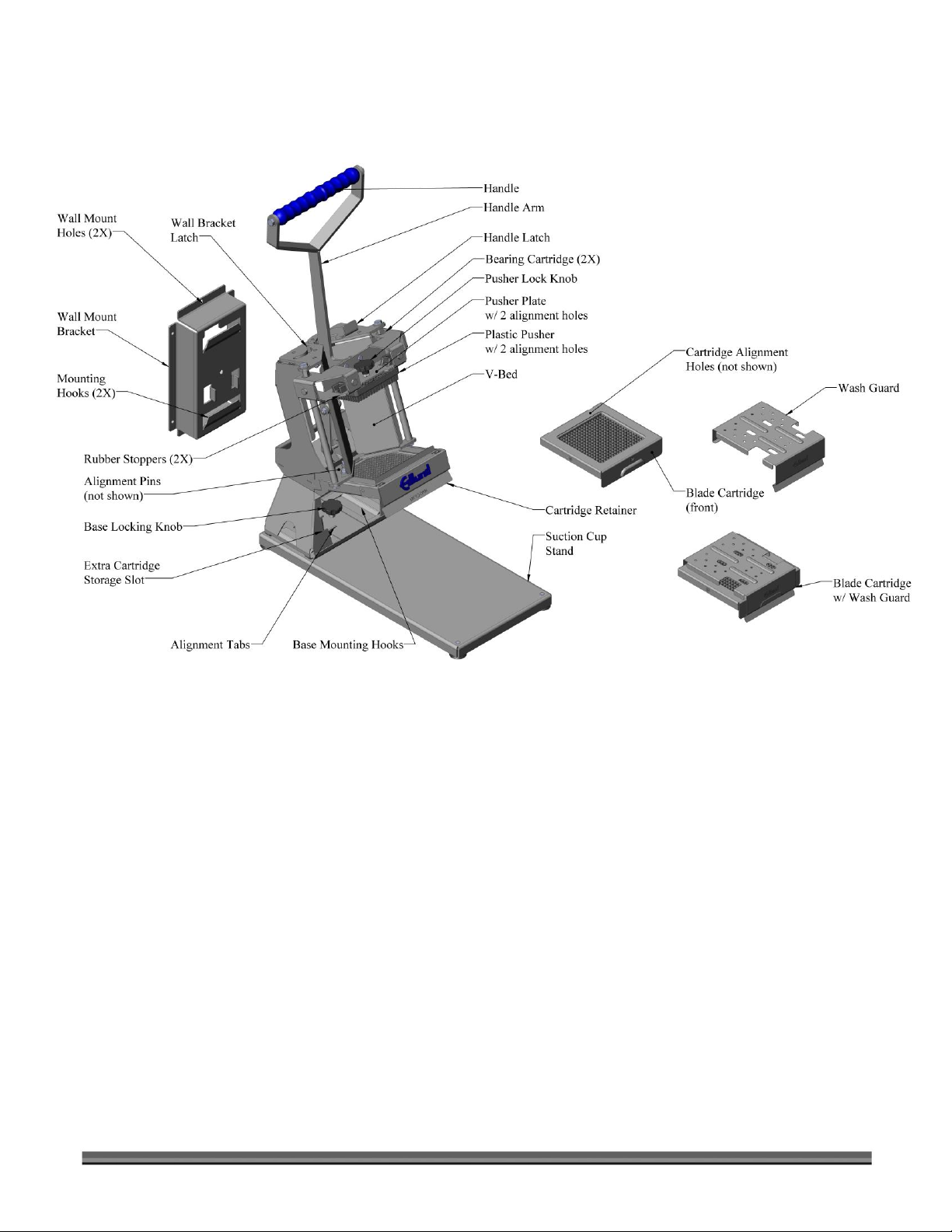
1. Remove any Blade Cartridges from the Extra Cartridge Storage Slot (Figure 2, page 9). See "Using the Extra
Blade Cartridge Storage Slot" for instructions.
2. Lift the Handle to its full upright position.
3. Rotate the Handle Latch (Figure 2, page 9) clockwise to secure the Handle in the upright position.
4. Place the Max-Cut on the Suction-Cup Stand, positioning the Base Mounting Hooks (Figure 2, page 9) on the
Stand within the corresponding notches in the Max-Cut Base.
5. Slide the Max-Cut to the left until the Alignment Tabs (Figure 2, page 9) fully engage with the notches in the
Base of the Max-Cut.
6. Turn the Base Locking Knob (Figure 2, page 9) clockwise until it is tight against the Base of the Max-Cut.
Removing the Max-Cut from the Suction-cup Stand
1. Remove any Produce Pans from the Discharge Area below the Blades.
2. Remove any Blade Cartridges from the Extra Cartridge Storage Slot (Figure 2, page 9). See "Using the Extra
Blade Cartridge Storage Slot" for instructions.
3. Lift the Handle to its full upright position.
4. Rotate the Handle Latch (Figure 2, page 9) clockwise to secure the Handle in the upright position.
5. Unscrew the Base Locking Knob (Figure 2, page 9) until it disengages from the Suction-Cup Stand.
6. Slide the Max-Cut to the right, disengaging the Base Mounting Hooks in the Stand from the unit.
7. Lift the Max-Cut away from the Stand.
Installing the Max-Cut on the Wall Mount Bracket
1. Remove any Blade Cartridges from the Extra Cartridge Storage Slot (Figure 2, page 9). See "Using the Extra
Blade Cartridge Storage Slot" for instructions.
2. Lift the Handle to its full upright position.
3. Rotate the Handle Latch (Figure 2, page 9) clockwise to secure the handle in the upright position.
4. Ensure the Wall Bracket Latch (Figure 2, page 9) is not engaged by rotating clockwise, to the unlock position.
5. Align the Mounting Hooks (Figure 2, page 9) with the Notches on the Rear of the Max-Cut.
6. Lower the Max-Cut until it is fully seated within the Wall Mounting Hooks, ensure both Mounting Hooks are
engaged.
7. Rotate the Wall Bracket Latch (Figure 2, page 9) counterclockwise to engage with the Wall Mount Bracket.
Removing the Max-Cut from the Wall Mount Bracket
1. Remove any Blade Cartridges from the Extra Cartridge Storage slot (Figure 2, page 9). See "Using the Extra
Blade Cartridge Storage Slot" for instructions.
2. Lift the Handle to its full upright position.
3. Rotate the Handle Latch (Figure 2, page 9) clockwise to secure the Handle in the upright position.
4. Rotate the Wall Bracket Latch (Figure 2, page 9) clockwise to disengage from the Wall Mount Bracket.
5. Lift the Max-Cut straight up until the Wall Mounting Hooks on the Wall Mount Bracket are disengaged from
the Max-Cut.