1.1 E-Flow Brief
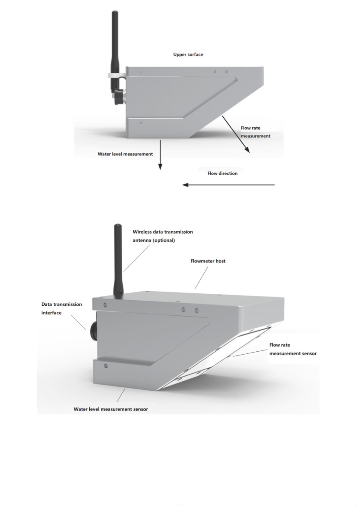
The E-Flow is a non-contact fully integrated flow monitor continuously measures flow, depth of flow, and
velocity. The E-Flow uses highly accurate and reliable radar planar microwave technology to capture the true
velocity and depth of flow zero contact with the flow. With the simple software to configure your E-Flow you
can record and measure flow in any channel shape, whilst sending measure flow, level, and velocity
seamlessly over the 4G network to view in realtime on the cloud platform. !
The E-Flow support digital (RS485, RS232) or analog (4-20mA) transmission of recorded data, using
standard Modbus-RTU protocol. The E-Flow is designed to operate in the harshest of environments for
longer with ultra low power consumption, compact sizing, highly reliable, simple set up, and almost zero
maintenance. Also the E-Flow is not affected by environmental factors such as debris in the flow, large
volumes of sediment, river pollutants, and floating objects!
1.2 Measuring Principle
The E-Flow meter uses doppler planar microwave technology to measure over 10,000 velocity points to
record a true average velocity for your measured area. The E-Flow also uses the doppler micro strip radar
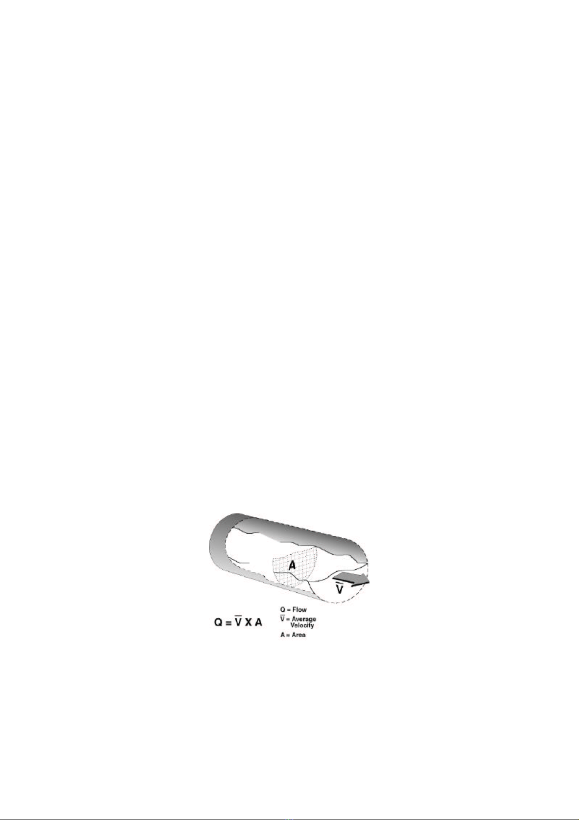
technology to record the depth of flow. By using the industry standard velocity-area method, the water level
is measured to convert the cross-sectional area, and then the average velocity is converted from the true
average velocity combined with the cross-sectional parameters. The empirical formulas for the velocity
distribution of the open channel cross section such as circular, rectangular and trapezoidal are established,
and the hydraulic model algorithm is used to obtain Flow rate is a non-contact flow measuring instrument
that accurately measures the flow rate without changing the boundary conditions of channels, rivers, pipes,
etc.!
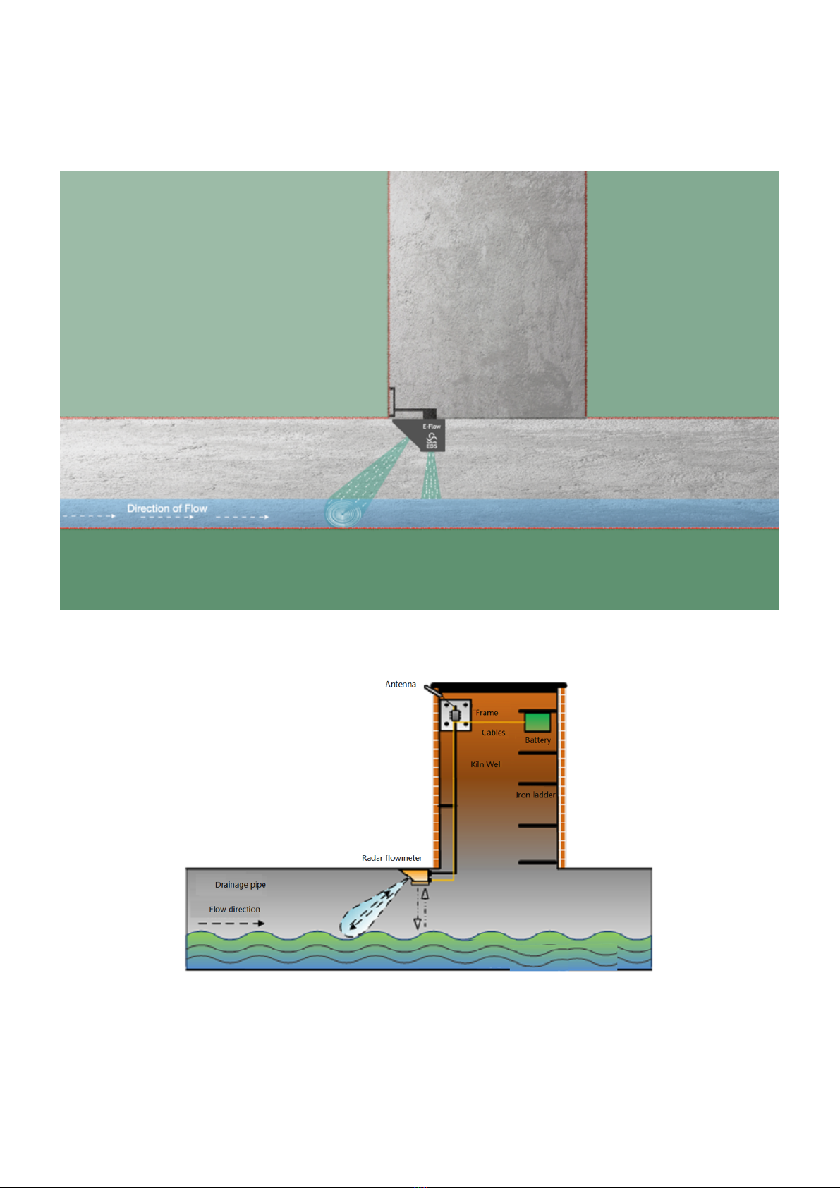
1.2.1 Flow Rate Measurement Principle
The radar velocity meter uses the principle of Doppler radar velocity measurement. When measuring the
speed of the water surface, the radar velocity sensor emits microwaves to the water surface, and the
microwaves will be absorbed and reflected from the water surface. The reflected wave is received by the E-
Flow and is then converted into an electrical signal, which is processed and the Doppler frequency shift is
measured.!