PowerShield m-Senzor User manual

© 2015 Pow erShield Ltd.
Sentinel Installation Manual
m-Senzor

Sentinel Installation Manual m-Senzor
2
© 2015 PowerShield Ltd.
Contents
Table of Contents
1Introduction 4
2Definitions for this Manual 5
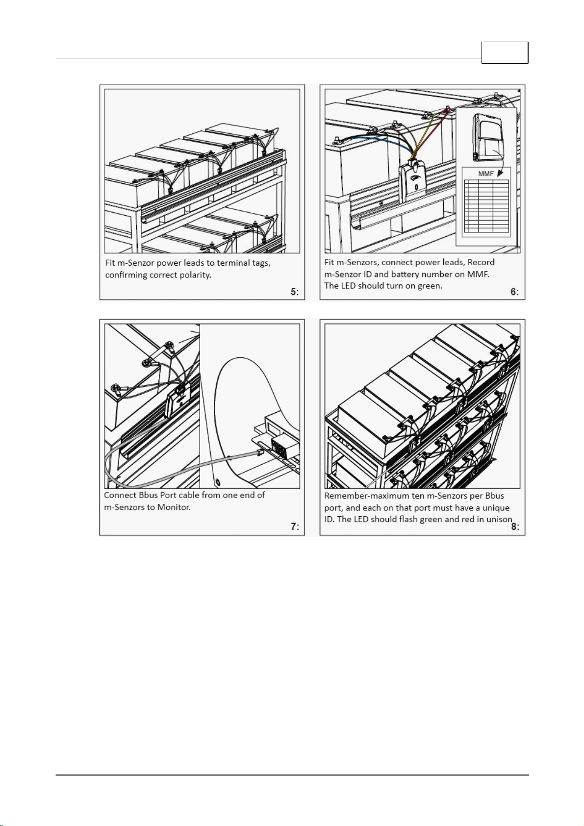
3Installation QuickGuide 6
4The SENTINEL Battery Monitoring System 9
................................................................................................................................... 10
Installation - Preliminaries
.......................................................................................................................................................... 10Sentinel Monitor
.......................................................................................................................................................... 10Pow er Supply
.......................................................................................................................................................... 10Faceplate
.......................................................................................................................................................... 11System Capacity
.......................................................................................................................................................... 11Sentinel Communications
.......................................................................................................................................................... 12m-Senzor
.......................................................................................................................................................... 13BBus ................................................................................................................................... 13
Installation
.......................................................................................................................................................... 13Step 1 - Monoblocks/Jars
.......................................................................................................................................................... 14Step 2 - Sentinel
......................................................................................................................................................... 14Set the Sentinel ID
......................................................................................................................................................... 14Mount and Pow er Up the Sentinel
.......................................................................................................................................................... 15Step 3 – Mounting Rail for m-Senzors
.......................................................................................................................................................... 15Step 4 – m-Senzor Pow er Leads
.......................................................................................................................................................... 16Step 5 – Connect m-Senzors
.......................................................................................................................................................... 17Step 6 – Connect the BBus
.......................................................................................................................................................... 18Step 7 – Connecting the Current Transducer
.......................................................................................................................................................... 19Step 8 – Connecting the Temperature Probe
.......................................................................................................................................................... 19Step 9 – Communications
.......................................................................................................................................................... 20Step 10 – Confirmation
5Appendix 1 - LED Behaviour 21
................................................................................................................................... 21
Sentinel................................................................................................................................... 22
m-Senzor
6Appendix 2 – Sentinel Rear Panel 23
7Appendix 3 - Communications 24
................................................................................................................................... 24
Service Port
................................................................................................................................... 24
Port 1 ................................................................................................................................... 25
Port 2 ................................................................................................................................... 26
Port 3
8Appendix 4 - Relay Outputs and Auxillary Inputs 27
................................................................................................................................... 27
Alarm Output Relays
................................................................................................................................... 27
Auxillary Inputs
9Appendix 5 - m-Senzor Connections 28
................................................................................................................................... 28
Dual m-Senzor Power Lead Connection Detail
................................................................................................................................... 28
Single m-Senzor Power Lead Connection Detail
10 Appendix 6 - Installation Forms 29
................................................................................................................................... 29
Site Identification Form (SIF)

3Contents
Sentinel Installation Manual m-Senzor © 2015 PowerShield Ltd.
................................................................................................................................... 30
String Configuration Form (SCF)
................................................................................................................................... 31
Monoblock Mapping Form (MMF)
11 Appendix 7 - Monitor & m-Senzor Replacement 32
................................................................................................................................... 32
Replace a Monitor
................................................................................................................................... 32
Replace an m-Senzor
12 Appendix 8 - Models and Part Numbers 34
................................................................................................................................... 34
Sentinels
................................................................................................................................... 35
m-Senzors
................................................................................................................................... 36
m-Senzor Leads
13 Appendix 9 - Specifications 37
................................................................................................................................... 37
Sentinel

Sentinel Installation Manual m-Senzor
4
© 2015 PowerShield Ltd.
Introduction
1 Introduction
This manual is intended for use with SENTINEL battery monitoring systems that use the m-Senzor range of
devices. This includes the full upgrade path from the voltage onlym-Senzor to the voltage/temperature/
ohmic value m-Senzor.
Note: This manual does not cover the installation of SENTINEL systems that use Measurement Modules.
(Refer to the document 6300-011 PowerShield Sentinel Installation Manual).
This manual describes the system hardware, and does not include information on configuring the system.
For information on configuring a SENTINEL system, refer to the document 6300-002 PowerShield
Configuration Software.
Part Number 6300-055F
September 2015
The information contained in this manual is copyright, and is not to be reproduced without the written
authority of PowerShield Ltd
PowerShield Limited
PO Box 102-190
NSMC
North Shore City 0745
New Zealand

Definitions for this Manual
Sentinel Installation Manual m-Senzor
5
© 2015 PowerShield Ltd.
2 Definitions for this Manual
Cell
the basic electrochemical unit to receive, store, and deliver electrical energy
Monoblock
one or more cells in a container also known as a battery. The terms
monoblock and jar are interchangeable. For this manual the term has been
standardised as monoblock to avoid using the somewhat unwieldy
convention of "monoblock/jar" throughout
String
two or more monoblocks connected in series
Battery Bank
complete system of parallel connected strings

Sentinel Installation Manual m-Senzor
6
© 2015 PowerShield Ltd.
Installation QuickGuide
3 Installation QuickGuide

Installation QuickGuide
Sentinel Installation Manual m-Senzor
7
© 2015 PowerShield Ltd.

Sentinel Installation Manual m-Senzor
8
© 2015 PowerShield Ltd.
Installation QuickGuide

The SENTINEL Battery Monitoring System
Sentinel Installation Manual m-Senzor
9
© 2015 PowerShield Ltd.
4 The SENTINEL Battery Monitoring System
The PowerShield Sentinel system is a permanent batterymonitoring system developed byPowerShield
Limited. The system can monitor one or more strings of monoblocks. Each monoblock is monitored via an
m-Senzor connected across the monoblock terminals. The Sentinel interrogates each m-Senzor and
processes the data, logging information into memoryat predefined intervals. Where there are strings of
different voltage monoblocks, a single Sentinel can monitor the whole battery system.
The Sentinel system incorporates hardware consisting of the Sentinel monitor and m-Senzors, and the
following software:
Configuration software for system configuration (refer to document 6300-002 PowerShield
Configuration Manual)
Link software for automated multi-site batterymanagement (refer to document 6300-017 Link
Manual)
Parameters measured include
voltage of each monoblock
ohmic value of each monoblock
string current
ambient temperature
Each system consists of at least one Sentinel monitor, an m-Senzor for each pair of monoblocks being
monitored, temperature probe and current transducer. An RS232 serial communication port has been
provided to be used with Configuration and Link software. For larger systems, multiple Sentinel monitors
can be 'daisy-chained'. See the topic System Capacity. Optional communications hardware is available.
Important
The SENTINEL system must be correctly installed and configured in order to obtain accurate results. The
installation of the system must be carried out only bysuitably trained personnel. Installation must be in an
adequately ventilated environment or warranty may be invalidated.
The SENTINEL system operates in a potentiallyhazardous environment making it imperative that all
installation personnel have adequate training and experience. The PowerShield m-Senzors must be
installed in a Service Access area.
UL Safety Rack Mount Instructions
A) Elevated Operating Ambient - If installed in a closed or multi-unit rack assembly, the operating
ambient temperature of the rack environment may be greater than room ambient. Therefore,
consideration should be given to installing the equipment in an environment compatible with the
maximum temperature specified in Appendix 9 - Specifications.
B) Reduced Air Flow - Installation of the equipment in a rack should be such that the amount of air
flow required for safe operation of the equipment is not compromised.
C) Mechanical Loading - Mounting of the equipment in the rack should be such that a hazardous
condition is not achieved due to uneven mechanical loading.
D) Circuit Overloading - Consideration should be given to the connection of the equipment to the
supply circuit and the effect that overloading of the circuits might have on over-current protection and
supply wiring. Appropriate consideration of equipment nameplate ratings should be used when
addressing this concern.
E) Reliable Earthing - Reliable earthing of rack-mounted equipment should be maintained. Particular
attention should be given to supply connections other than direct connections to the branch circuit
(e.g. use of power strips).

Sentinel Installation Manual m-Senzor
10
© 2015 PowerShield Ltd.
The SENTINEL Battery Monitoring System
4.1 Installation - Preliminaries
4.1.1 Sentinel Monitor
Width:
430mm / 17 inches (19” rack compatible)
Depth:
270mm / 10.6 inches
Height:
45mm / 1.8 inches (1U)
4.1.2 Power Supply
The Sentinel is available in the following power supplymodels:
48V DC Model: Range of input voltage is 20V-65VDC, max0.4A per Sentinel.
72V DC Model: Range of input voltage is 55V-140VDC, max0.40A per Sentinel.
Input connector is a 3 way plug and screw terminal block.
The power supply must be fused.
Must be installed in a service access area.
AC Model: Range of input voltage is 110V-240VAC (50/60Hz), max 0.15A per Sentinel.
Input connector is a male IEC input. IEC mains cable is supplied.
Note that the DC units cannot be powered with AC voltage and that the AC units cannot be powered with
DC voltage.
Ensure that the correct power supply for Sentinel units is being used prior to applying power.
Both AC and DC models must be installed by a service person and connected to a socket outlet or
fixed wiring with a protective earthing conductor or connector.
A readilyavailable disconnect device shall be incorporated in the building wiring or the socket outlet,
near the Sentinel, and be readily accessible.
To ensure that the system operates during a power failure, it is recommended that the monitor is
powered by a batterybacked supply rather than from a mains adaptor.
4.1.3 Faceplate
The faceplate, label and LED arrangement of the Sentinel is shown below. Refer to Appendix 1 for a full
description of LED behaviour.

The SENTINEL Battery Monitoring System
Sentinel Installation Manual m-Senzor
11
© 2015 PowerShield Ltd.
4.1.4 System Capacity
Every system must have a Sentinel master unit, and additional Sentinel units may be added as slaves to
increase capacityof the overall system. The Sentinel master unit has 8 Bbus ports, with each port
supporting up to 10 m-senzors (20 monoblocks). Therefore, if there are more than 160 monoblocks in a
system, additional Sentinel units are required. Similarly, if there are more than 5 battery strings in a system,
additional Sentinel units are required. Amaximum of 16 units, including the master, can be connected.
The position of the rotary switch at the rear of the Sentinel determines the identification number of the unit.
The Master must be set to 0, Slaves may be 1-9 or A-F, ensuring that each figure is used onlyonce in the
system. Each unit is identified by the switch setting.
Refer to Appendix2 for a diagram of the Sentinel rear panel.
4.1.5 Sentinel Communications
All external communications must operate through the Master unit, a Slave will not communicate.
Item
Connection
Type
Used for...
A
Service Port
RS232
Temporary local connections.
B
Port 1 (Optional)
Ethernet
Permanent local or remote monitoring connections.

Sentinel Installation Manual m-Senzor
12
© 2015 PowerShield Ltd.
The SENTINEL Battery Monitoring System
Item
Connection
Type
Used for...
C
Port 2 (Optional)
RS485 or
RS232
Permanent connection to third party systems.
D
Port 3
Sentinel system communications. Master to Slave
and Slave to Slave.
4.1.6 m-Senzor
Each m-Senzor is specific to the monoblock voltage to which it will be fitted, e.g. 2V / 6V / 12V.
The m-Senzor is a dual device and is connected across a pair of monoblocks. The pair of monoblocks
must be located one after the other in a series, within the same battery string. The most positive
monoblock of the pair is V1, the most negative monoblock of the pair is V2. The m-Senzor measures each
monoblock individually.
Each m-Senzor has a factory set ID number between 1 and 125. Any m-Senzor can be fitted to any'in
series' pair of monoblocks, regardless of ID number; however, each m-Senzor in a single BBus must have
a unique ID.
For installations containing strings with uneven numbers of monoblocks, or where layout makes pairs
impossible, a one monoblock ‘single’ version of the m-Senzor is available. This is identical to and treated
in the same manner as the dual version, but connected across a single block. The label on the m-Senzor
will show whether it is single or dual. See sample Dual label below.
Refer to Appendix1 for m-Senzor LED behaviour.

The SENTINEL Battery Monitoring System
Sentinel Installation Manual m-Senzor
13
© 2015 PowerShield Ltd.
4.1.7 BBus
M-Senzors communicate with the Sentinel via the BBus. This connects m-Senzor to m-Senzor and m-
Senzor to Sentinel in a chain. One BBus is not limited to a single string, or even consecutive monoblocks. If
it is more practical, each BBus may span between strings.
The BBus is capable of connecting up to 10 m-Senzors together. However, it is not necessaryto fullyload
each BBus. Depending on the layout of the system, it may be more convenient to have 10 m-Senzors on
one BBus and 5 on another for example.
A single BBus must not be greater than 150m in length. This is the total length of the BBus to the furthest
module, including the short connecting cables between each m-Senzor.
4.2 Installation
Complete the forms as the hardware is being installed. Correct configuration of the system relies on
accurate installation records.
Copies of the installation forms can be found in Appendix6.
4.2.1 Step 1 - Monoblocks/Jars
Each monoblock must be uniquelyidentified with a number between 1 and 1280. It does not matter which
numbers are allocated to which monoblock, although monoblocks in a single string must be in a single
consecutive sequence of numbers. Where there are multiple strings in a system, ensure every monoblock
is uniquely identified, ie. 1-24, 25-48, 49-72 NOT 1-24, 1-24, 1-24.
Ensure that all terminals have 6.3mm tabs available for m-Senzor connection as following:
Where a dual m-Senzor is to be used – fit two tabs on the negative (-) terminal of the most negative
monoblock and two tabs on the positive (+) terminal of the most positive monoblock. Fit one tab on
each of the remaining terminals.
Where a single m-Senzor is to be used – two tabs are required on each monoblock terminal.
For simplicity, it maybe easier and more efficient to fit two tabs to every terminal.

Sentinel Installation Manual m-Senzor
14
© 2015 PowerShield Ltd.
The SENTINEL Battery Monitoring System
Number all monoblocks individually 1-1280 (e.g. 1-32, 33-63, 65-96 NOT 1-32, 1-32, 1-32).
Fit terminal tags, 2 tags per post.
IMPORTANT: Place the tags on top of the interlinks, otherwise the current flow between the interlink and
the battery is reduced and could result in a 'hot spot'.
4.2.2 Step 2 - Sentinel
4.2.2.1 Set the Sentinel ID
Ensure that the rear connector panel and the cable tray can be safelyaccessed. If there is more than one
Sentinel in the system (Master – Slave), ensure that each unit’s ID switch is correctly set, and that the
Master is the unit with any additional communications at Port 1 or Port 2.
4.2.2.2 Mount and Power Up the Sentinel
The Sentinel unit is supplied in a 1U 84HP 19" standard case. Mount the Sentinel securely to a 19" rack
(not supplied), a wall, a shelf, or similar using the mounting brackets provided.
Note:Ensure the Sentinel unit is unable to move when installed - cables and connections must not be put
under strain.
Ensure the rear connector panel and cable tray can be safelyaccessed. If there is more than one Sentinel
in the system [Master – Slave], ensure that each unit’s ID switch is correctly set, and that the Master is the
unit with any additional communications at Port 1 or Port 2.
When the Sentinel is powered up, it will emit an audible alert, and the green Power LED will light. Other
LEDs on the front panel may also light.
Install the Sentinel securely. Power up and confirm operation.

The SENTINEL Battery Monitoring System
Sentinel Installation Manual m-Senzor
15
© 2015 PowerShield Ltd.
4.2.3 Step 3 – Mounting Rail for m-Senzors
The m-Senzor mounting rail can be fitted in anyorientation and can be used with both battery racks and
cabinets. Drill to suit and fasten with screws or cable ties.
Secure the mounting rail to suit battery layout.
4.2.4 Step 4 – m-Senzor Power Leads
Fit the m-Senzor power leads to the battery terminals.
Ensure the dual power leads are connected across an ‘in series’ pair of batteries.

Sentinel Installation Manual m-Senzor
16
© 2015 PowerShield Ltd.
The SENTINEL Battery Monitoring System
Dual power lead connection Single power lead connection
Fit all m-Senzor power leads to terminal tags, confirming polarity
4.2.5 Step 5 – Connect m-Senzors
Connect the m-Senzors to the power leads and snap into mounting rail. Ensure the ID and monoblock
number are recorded on the Monoblock Mapping Form (MMF). Without this information the system cannot
be properly configured. The ID range is 1-125, however the m-Senzors can be installed in any
arrangement. The onlyrequirement is that when connected to the Sentinel each m-Senzor on a BBus port
has a different ID.
The LED should light solid green when the m-Senzor is powered correctly. If the LED lights red, check the
connections of the power lead.
A full list of m-Senzor LED states is available at Appendix 1

The SENTINEL Battery Monitoring System
Sentinel Installation Manual m-Senzor
17
© 2015 PowerShield Ltd.
Fit modules and connect power leads
The LED should turn green
Record m-Senzor ID and monoblock number on MMF form
4.2.6 Step 6 – Connect the BBus
The BBus is the communications link between m-Senzors and Sentinel. The BBus is single ended [not a
loop] and connects up to ten m-Senzors to a single Sentinel BBus port. The m-Senzors can be connected
in anyarrangement, so long as each m-Senzor on a BBus has a different ID number.
Use the short BBus interconnect cables from m-Senzor to m-Senzor, and the longer BBus port cables from
m-Senzor to Sentinel.

Sentinel Installation Manual m-Senzor
18
© 2015 PowerShield Ltd.
The SENTINEL Battery Monitoring System
Connect BBus port cable from one end of the m-Senzors to the Monitor.
Once the BBus is connected to a powered Sentinel, the m-Senzor LEDs should flash green and red in
unison.
Note a maximum of 10 m-Senzors per BBus and each on that port must have a unique ID.
4.2.7 Step 7 – Connecting the Current Transducer
A current transducer is required per battery string to measure the battery current. Up to 5 transducers can
be connected to a Sentinel.
The transducer can be fitted anywhere on the primary batteryconductor, but polarity is important. For URD
and LEMtransducers, if the transducer is installed with the arrow pointing in the direction of conventional
current flow when charging, you should enter a negative gain when configuring. Record the direction on the
String Configuration Form. For example, in the diagram below, transducers 1 & 3 are considered positive
while transducer 2 is considered negative.

The SENTINEL Battery Monitoring System
Sentinel Installation Manual m-Senzor
19
© 2015 PowerShield Ltd.
Install current transducer and connect with cable to Monitor
Record details on SCF form
4.2.8 Step 8 – Connecting the Temperature Probe
A temperature probe is required per battery string to measure the ambient temperature. Up to 5
transducers can be connected to a Sentinel.
Locate the probe in the middle of the batteryrack or cabinet, but be aware of other items that may be
affecting the local environment – HVAC, plant etc.
Install temperature probe and connect to Monitor
Record details on SCF form
4.2.9 Step 9 – Communications
Connect appropriate communications cabling and devices. The Sentinel supports a range of external
communications.

Sentinel Installation Manual m-Senzor
20
© 2015 PowerShield Ltd.
The SENTINEL Battery Monitoring System
See Appendix 3 for more information on specific options and wiring.
4.2.10 Step 10 – Confirmation
Check that all installed parts are performing as expected and that the installation forms are complete.
Secure all cables with appropriate strain relief.
Confirm all module LEDs are flashing
Secure all cables tidily
Your SENTINEL system is now readyfor configuration.
You will require Config software and the associated manual, 6300-002 PowerShield Configuration Manual.
Proceed with system configuration using Config software
Ensure completed MMF and SCF forms are available
Table of contents
Popular Accessories manuals by other brands

Audient
Audient iD14 user manual

Omron
Omron ZW-8000 Series user manual

Oliver Kessler
Oliver Kessler SOLITAIRE PUNKAH Installation & owner's manual

Siemens
Siemens SITRANS WW300 operating instructions

Elsner
Elsner KNX LW Series Technical specifications and installation instructions

Bosch Sensortec
Bosch Sensortec BNO055 quick start guide