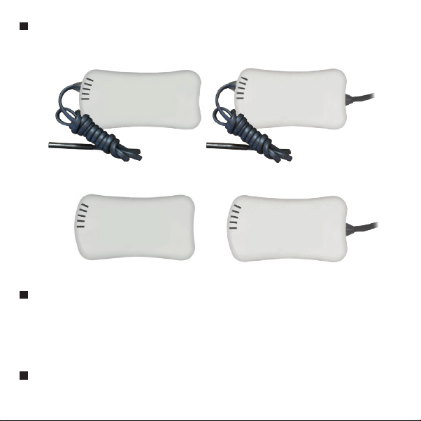
Product Family
eSense appliance is designed to detect temperature, pressure, humidity, noise
and voltage & frequency changes. The system consists of control panel and
sensors and used in wide range of applications and markets such as medical,
pharmaceutical, industrial, commercial and many more. eSense transmits the
sensor data with wire or wireless 24/7 to the server. Stored data are available
as report and user is able to view graphically from web interface and mobile
application.
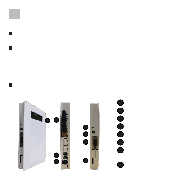
DESCRIPTION
1
2
P/N Description
EMS-100GSM GSM Monitoring Panel
EMS-100L Wired Monitoring Panel
EMS-100WL Wireless Monitoring Panel
ENS-100 Wired Humidity Sensor
ENS-100T Wireless Humidity Sensor
ES-100 Wired Temperature Sensor
ES-100T Wireless Temperature Sensor
EB-100 Wired Pressure Sensor
EB-100T Wireless Pressure Sensor
EGS Noise Sensor
EVF-100 Voltage and Frequency Sensor
EIO-100 Digital Access Module
EMAS-100 Analog Access Module