3
EDS - TECHNICAL INFORMATION
1.11 - When beign certain of the automatic spark
extinguishing is necessary or in important installations,
where security should be set at the highest level, we
suggest to install another detector (or detectors couple)
at a suitable distance from the detector or couple of
detectors already installed, for a forward confirmation of
the performed extinguishing. Ifextinguishing was performed
correctly this second detector will stay inactive, otherwise it
will activate and its output relay will be used to :
•activate a second sprinkler spraying nozzle for a
second extinguishing attempt
•close the output mounth of the pipe by means of an
automatic shutter before the materials are deployed
in the Silo
•activate a suitable acoustic alarm
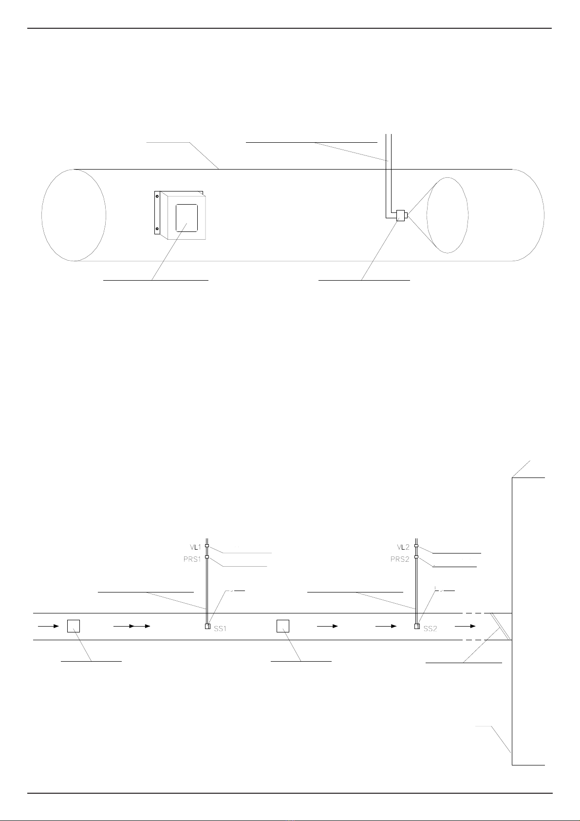
2 - OPERATION
2.1 - With reference to fig. 5 about a 2 detectors
installation, if a burning spark passes through the first
detector's field of view, the EV395 detector gets in
alarm condition, its output relay immediately activates
and remains activated for a time duration equal to the
one set with P2 trimmer between 0 and 10 seconds.
The output contact of this relay will be used to drive
VL1 electrovalve that will activate the water spraying
by the SS1 noozle for a first extinguishing attempt.
2.2 - If the spark has been extinguished, the system
returns to normal operation, otherwise the spark,
continuing its ride, wil enter in the field of view of the
second EV395 detector.
This will activate its output relay. The contact of this
relay will drive VL2 electrovalve that will activate the
water spraying by the SS2 noozle for a second
extinguishing attempt.
3- RESPONSE TIME
3.1 - The times to evalauate during the designing
process of a spark detection system are the following:
T1 - response time of EV395 detector
T2 - response time of the detector's output relay
T3 - acquisition time of EV521 Control Unit and
response time of its relay
T4 - response time of extinguishing electrovalve VL
T5 - filling time of the part of pipe goig from the
electrovalve to the noozle SS and time of water
cone generation
If in the system there's no EV521 Control Unit
included the time relative to the Control Unit (T3)
shall not be counted.
The usual values of this times are:
T1 - 3 ms
T2 - 1 ms
T3 - 10 ms
T4 - 2 ms
T5 - depends on pipe lenght, pipe section and most
of all on water pressure
3.2 - For designing calculations the T1-T4 time can
be considered of 60 ms max.
The T5 time should be added to that. This time is
dependent on the pipe sectionand lenght, on water
presssure and on the used noozle. With a SP34F22
noozle and a water pressure of 3-4 bar a water
speed of 4-6 m/s is obtained. So if the piece of
pipe between electrovalve and noozle is 1 m long,
the transit time is around 0.2 s.
Therefore summing the T1-T5 times the result is
0,22 s.
This is the system response time.
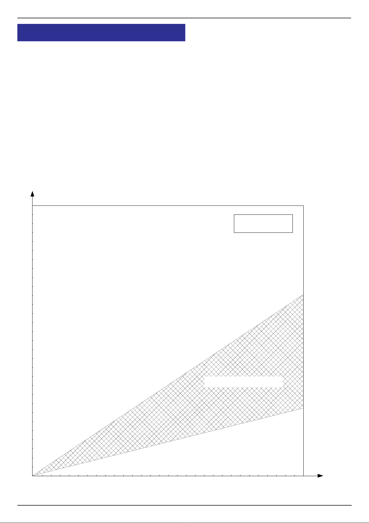
4- NOZZLE POSITIONING
4.1 - The spaying noozle has the function of
extinguishing the spark.
Its position must be calculated taking in account the
times detailed in the previous chapter and the
speed of the fluid or materials flowing in the pipe.
For a calculation of the mean value, a simple
Physics formula can be used:
S = vt
where :
S= covered lenght in meters
v= speed of the fluid in the pipe m/s
t= response time of the security system
The fluid speed has to be measured in place.
Normally the following speed is measured:
•wood industry : 20-30 m/s
•textile industry : 10-20 m/s
For other applications a measurement is required.
So the calculation is simple knowing the 3
parameters of the formula.