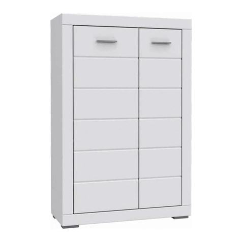
Edsal RTA361872-BLK User manual

RTA TALL CABINET
Model# RTA361872-BLK
ASSEMBLY GUIDE
Quesons, problems, missing parts?
Contact us directly for assistance:
7 a.m. - 5 p.m., CST, Monday-Friday
Chat: www.edsal.com
Phone: 1-773-475-3131
To obtain replacement parts please provide:
Model Number, Descripon and Date of Purchased.
THANK YOU FOR YOUR PURCHASE rev: C041723_V2
EDSAL MANUFACTURING CO, LLC | 1555 W. 44TH STREET | CHICAGO, IL 60609 | www.edsal.com

SAFETY INFORMATION
2
WARNING: TO REDUCE THE RISK OF SERIOUS INJURY, READ AND FOLLOW THE SAFETY
INSTRUCTIONS BELOW BEFORE ASSEMBLING AND USING THIS PRODUCT.
• This product is intended for indoor use only.
• This product is not designed for commercial or industrial usage.
• Use at least two people to assemble and move this product. Failure to do so can result in personal injury or
product damage.
• Any assembly or maintenance of this product must be carried out by adults only.
• Keep the product on a level surface. The product could become unstable and may p over if stored or moved
on an uneven surface, which may cause product damage, personal injury, or death.
• Do not leave children unaended near this product. Cabinet can p over if improperly opened.
• DO NOT stand on this product or use it as a ladder or scaold.
• DO NOT alter this product in any manner.
• DO NOT put anything on the top panel of this product.
• Do not exceed the maximum load capacity for each shelf and the enre unit.
• Retain this manual for future reference.
Cabinet Dimensions: 36 in. W x 18 in. D x 72 in. H
Maximum load capacity for each shelf and boom level: 300 lbs. / 136 kg
Maximum load capacity for the enre unit: 1200 lbs. / 544.3 kg
• Begin by placing the package on a at surface. Use a rug to protect the cabinet and oor.
• Remove all parts and dispose/recycle all packaging materials.
• Check to make sure all parts are present.
Edsal Manufacturing Company, LLC products are guaranteed for a period of one (1) year from the date of purchase. The SOLE
AND EXCLUSIVE REMEDY for such defects is the repair or replacement of a defecve product or parts thereof by Edsal Manufac-
turing Company, LLC or, at Edsal Manufacturing Company, LLC opon, refund of the purchase price upon return of the item to
Edsal Manufacturing Company, LLC. This warranty shall not apply in the event the products are damaged as a result of misuse,
neglect, accident, moisture, improper applicaon, improper assembly, or assembly not in conformity with the instrucons of
Edsal Manufacturing Company, LLC, failure to abide by safety precauons prescribed by Edsal Manufacturing Company, LLC or
modicaon or repair by persons not authorized by Edsal Manufacturing Company, LLC.
PRE-INSTALLATION
WARRANTY
SPECIFICATIONS
TOOLS REQUIRED (not included): Rubber Mallet or So Face Hammer
Note: If using a hammer, a cloth should be
used over the parts to protect the paint.
Leveler

A (x1)
Le Side
Panel
D (x1)
Le Back
Panel
C (x6)
Beam
G (x2)
Fixed Shelf
F (x1)
Top Panel H (x2)
Adjustable
Shelf
I (x1)
Le Door
J (x1)
Right Door
N (x20)
Push Buon Pin
(note: extra pins are included)
M (x2)
Top Door
Hinge
E (x1)
Right Back
Panel
PACKAGE CONTENTS
B (x1)
Right Side
Panel
K (x4)
Leg Leveler
O (x2)
Rubber
Grommet
3
L (x8)
Shelf
Clip

4
ASSEMBLY
Insert Leg Levelers (K) into the boom holes of Le Side Panel (A) and Right Side Panel (B).
Inside view
✓
Tap down on beam
to seat the tabs
STEP 2:INSTALL BEAMS
STEP 1: INSTALL LEG LEVELERS
FIG. 1
FIG. 2
K
✓
Slots
Tabs should t
snug into the
boom of slots
Tabs face down
Start by installing two Beams (C) to the middle secon of Side Panels (A) and (B), both front and back. Do this by inserng the
two end tabs on each side of the beam into the two slots of each side panel. Be sure the tabs are facing downward and the
ledge is facing upward when installing the beams (see Fig. 1). Use a rubber mallet or hammer (with a cloth) to lightly tap down
on the beam to secure the tabs into the boom of the slots (see Fig. 2). Note: If the beams are too loose and pop up, the tabs
may need to be lightly pressed inward, this will ensure a ghter t into the boom of the slots. Repeat the steps to install two
Beams (C) into the boom secon, followed by installing two Beams (C) into the top secon, both front and back.
Tip: If the beams are too loose and pop
up, adjust the tabs by gently pressing
them inward to ensure a ghter t.
Note:
Assemble the
middle two
beams rst.
Followed by
the boom
two beams,
then the top
two beams.
C
C
C
C
C
A
B
C
A
B
Tip: Recommended two-person
assembly for this step.

5
Aach the Le Back Panel (D) and Right Back Panel (E) onto the backside of each beam level. Do this by aaching each of the
tab hooks, located at the top, middle and boom of each inner back panel, onto each beam level (see Fig 3). Be sure all the tab
hooks are fully aached onto each beam (see Fig. 4).
ASSEMBLY (Connued)
Backview
Backview Front view
STEP 4: INSTALL TOP PANEL
Insert the Top Panel (F) over the side and back panels with the long ange facing the front (see Fig. 5). The long ange must be
seated behind the beam.
Tab Hooks
(6 total per back panel)
Back Panel
Beam
✓
✓
STEP 3: INSTALL BACK PANELS
FIG. 3
There are six total inner tab
hooks per back panel, located
at the top, middle and boom
to aach onto each beam level.
Flange
FIG. 5
Made sure all the tab
hooks are fully aached
onto each beam level.
✓
FIG. 4
Note: The long ange faces
the front and must be
seated behind the beam.
F

6
ASSEMBLY (Connued)
STEP 6: INSTALL SHELVES
Insert the two Fixed Shelves (G); one at the boom and one in the middle of the cabinet as shown (see Fig. 8). Next install the
two Adjustable Shelves (H) using four Shelf Clips (L) per shelf at the desired locaon. Insert the shelf clips into the slots (see Fig.
9) at the same height on all four sides per shelf, then place the shelf on top of the clips (see Fig 10).
✓
FIG. 8
L
Shelf
FIG. 10
FIG. 9
L
Slot
✓
STEP 5: INSTALL PUSH BUTTON PINS TO BACK PANELS
First be sure all holes from the back panel align with the holes from the side panels (see Fig. 6 for hole locaons). Install 12
Push Buon Pins (N) into the 12 hole locaons shown (see Fig. 6). Use a rubber mallet to gently tap in the push buon pins
unl fully engaged (see Fig. 7).
N
hole
N
FIG. 6
✓
FIG. 7
Tip: If the holes are not all
aligned, try slightly nudging
the panels unl fully aligned.
12 hole locaons
Note: Insert the Fixed Shelves
(G) at an angle, then lower
the shelf onto the beams and
the side panel louvers. Gently
press down to secure the shelf
so it sits leveled.
Note: Insert the Adjustable
Shelves (H) at an angle, then
lower the shelf onto the
Shelf Clips (L).
G
G
H
H

7
ASSEMBLY (Connued)
STEP 8: INSTALL DOORS
I
J
A
I
F
A
I
Install the Le Door (I) and Right Door (J) starng at the boom. Locate the hole at the boom of the door and place onto the
hinge located on the boom of the side panel (see Fig. 11). Next, insert the top door hinge into the top panel hole by pressing
down on the hinge and slightly liing the top panel for clearance if needed (see Fig. 12). Push the top panel back down to
secure the connecon.
boom
hinge
FIG. 11
FIG. 12
✓
STEP 7: INSTALL TOP DOOR HINGES
Insert the Top Door Hinges (M) into the hole located on the top end of Le Door (I) and Right Door (J).
IJ
Tip: The top door
hinge is spring
loaded and can be
pressed down to
help insert into the
top panel hole.
M
M

8
ASSEMBLY (Connued)
O
STEP 10: INSTALL RUBBER GROMMETS
STEP 11: FINAL INSPECTION
Install the two Rubber Gromments (O) into the two holes located on the back panels. Opon: Puncture a hole through the
“X” located on the gromments to allow for easy cords access.
Check to make sure the cabinet is leveled in its nal locaon,
using a leveler. Adjust the leg levelers if necessary.
✓
✓
STEP 9: INSTALL PUSH BUTTON PINS TO TOP PANEL
First be sure all holes from the top panel, back panel and side panels are aligned with one another (see Fig. 13 for hole
locaons). Install eight Push Buon Pins (N) into the 8 hole locaons shown (see Fig. 13). Use a rubber mallet to gently tap in
the push buon pins unl fully engaged (see Fig. 14).
N
8 hole locaons
FIG. 13
N
hole
FIG. 14
✓
Tip: If the holes are not all
aligned, try slightly nudging
the panels unl fully aligned.

9
PARTS LIST
P
Part Description Qty Part Number
A Left Side Panel 1 ASS7218-L
B Right Side Panel 1 ASS7218-R
C Beam 6 N2R-BM36-BLK
D Left Back Panel 1 ABKL7217
E Right Back Panel 1 ABKR7218
F Top Panel 1 AAT3618
G Fixed Shelf 2 ASF3618
H Adjustable Shelf 2 ASA3618
I Left Door 1 ADR7218-L
Part Description Qty Part Number
J Right Door 1 ADR7218-R
K Leg Leveler 4 RTALLGVL
L Shelf Clip 8 SCLIP-STD
M Top Door Hinge 2 HNG-TOP
N Push Button Pins 20 RTA-PUSHBUTTON
O Rubber Grommet 2 RTA-RUBBERGROMMET
PBottom Door Hinge
(preassembled on side panels) 2RTAFRONTLVR/
RTAFRONTLVL
QDoor Magnet
(preassembled inside of doors) 2RTAMAGNET
Q

•• Periodically check to make sure the beams tabs are secure into the slots of the side panels.Periodically check to make sure the beams tabs are secure into the slots of the side panels.
• Use a dry or slightly dampened, clean cloth to wipe down the cabinet if needed.
MAINTENANCE AND CARE
Take a survey about this
product by scanning the
QR code below:
Table of contents
Other Edsal Indoor Furnishing manuals

Edsal
Edsal Muscle Rack UR184884WR6 User manual
Edsal
Edsal Super Rack SR100 User manual
Edsal
Edsal 7000 User manual
Edsal
Edsal Muscle Rack 6600 Series User manual
Edsal
Edsal EBC30 User manual
Edsal
Edsal MUSCLERACK UR185P-BLK User manual
Edsal
Edsal MuscleRack Pro Series User manual
Edsal
Edsal MUSCLERACK MROP482472M User manual
Edsal
Edsal CB Series User manual
Popular Indoor Furnishing manuals by other brands
Kogan
Kogan OVELA BILLI BUTTON OVBILLISBGA user guide
Furniture of America
Furniture of America CM-AC827 Assembly instructions
BROSA
BROSA Elizabeth Nesting Tables Assembly guide

Home Decorators Collection
Home Decorators Collection PROVENCE BF-24686 Assembly instructions
Habitat
Habitat KASHA KASH-SS-09-A manual
Mopec
Mopec BC006 Reference manual
