Edson 120E User manual

146 DUCHAINE BLVD., NEW BEDFORD, MA. 02745-1292 TEL. 508-995-9711 FAX 508-995-5021 E-MAIL pumps@edsonintl.com
Page 1 The Pump
Page 2 Performance & Dimensions
Page 3 Installation Guidelines
Page 5 Operations
Page 7 Maintenance & Repair
Page 9 Trouble Shooting
Page 10 Parts
P-98-120E pg.1
Installation and Operations Manual
AModel120Eisbuiltwithdifferentoptionsthateffectperformanceand service.
lMake sure the pump received is the pump ordered. Compare the pump with the packing list.
lMake sure the parts list attached to this manual is the one for your pump.
lFillintheimportantpump information below
Turn to Page 6, Pump Construction Information, for details on comparing the pump with the Order #.
ENTER YOUR PUMP DATA HERE
PUMP MODEL #
PUMP SERIAL #
PUMP DRIVE: Motor
Reducer
From Packing Slip or Invoice i.e.. 120ELB-40-200
From Edson Serial # Sticker On Pump Frame i.e.. # 25748
From Plate On Motor and Reducer i.e.. Motor- 3/4hp,1 Phase, 60 HZ, 1725 RPM, TEFC.
FromPlate On Reducer- Nord Gear, 31 to 1 Ratio
ELECTRIC POWERED DIAPHRAGM PUMP MODELS 120E
The Pump
Index:
Page1The Pump

146 DUCHAINE BLVD., NEW BEDFORD, MA. 02745-1292 TEL. 508-995-9711 FAX 508-995-5021 E-MAIL pumps@edsonintl.com
S
U
C
T
I
O
N
H
E
I
G
H
T
DISCHARGE HEIGHT
56
Cycles
Per Min.
5 ft
1.5 m
1 ft
.3 m
10 ft
3 m
12 ft
3.7 m
05 ft
1.5 m 10 ft
3 m
38/144
30/114
28/106
28/106
32/121
30/114
26/98
26/98
24/91
23/87
16/61
14/53 gpm / lpm
DISCHARGE HEIGHT
30
Cycles
Per Min.
5 ft
1.5 m
1 ft
.3 m
10 ft
3 m
12 ft
3.7 m
05 ft
1.5 m 10 ft
3 m
20/77
17.5/66
17/64
13/49
19/72
17/64
16/61
12/47
17/64
16/61
15/57
10/38
S
U
C
T
I
O
N
H
E
I
G
H
T
40
Cycles
Per Min.
5 ft
1.5 m
1 ft
.3 m
10 ft
3 m
12 ft
3.7 m
05 ft
1.5 m 10 ft
3 m
27/102
21/81
20/76
20/78
23/87
21/81
19/70
19/70
17/64
16/62
11/43
10/38
DISCHARGE HEIGHT
S
U
C
T
I
O
N
H
E
I
G
H
T
DISCHARGE HEIGHT
20
Cycles
Per Min.
5 ft
1.5 m
1 ft
.3 m
10 ft
3 m
12 ft
3.7 m
05 ft
1.5 m 10 ft
3 m
14/52
11/42
10/38
10/38
11/42
11/42
9/34
9/34
9/34
8/31
6/22
5/19
S
U
C
T
I
O
N
H
E
I
G
H
T
DISCHARGE HEIGHT
36
Cycles
Per Min.
5 ft
1.5 m
1 ft
.3 m
10 ft
3 m
12 ft
3.7 m
05 ft
1.5 m 10 ft
3 m
24/92
19/73
18/68
18/68
21/78
19/73
17/63
17/63
15/58
15/56
10/39
8/30
S
U
C
T
I
O
N
H
E
I
G
H
T
DISCHARGE HEIGHT
13
Cycles
Per Min.
5 ft
1.5 m
1 ft
.3 m
10ft
3 m
12ft
3.7 m
05 ft
1.5 m 10ft
3 m
9/34
7/26
7/26
7/26
7/26
7/26
6/23
6/23
5/20
5/20
4/14
3/12
S
U
C
T
I
O
N
H
E
I
G
H
T
gpm /lpm gpm /lpm
gpm /lpm
P-98-120E pg.2
Pump Performance Is Dependent On Cycle Rate & Installation Head:
lVolume is expressed in GPM (gallons per minute) and LPM (liters per minute)
lCycle Rate is the rpm of the motor divided by the ratio of the reducer. i.e. 1725 rpm / 31= 56
lHead conditions are determined by the height, length and size of the installation plumbing to
and from the pump and the viscosity of the liquid.
General Specifications:
lStatic Head: Suction 15 ft / 4.57m Discharge 15 ft / 4.57m (2" Hose or Pipe)
lDry Suction Head: 12 ft / 3.65m (2"ID Pipe or Hose)
lContinuous Duty Discharge Heads: Should be Limited to 10 ft. / 3m
lPerformance: 38 GPM / 144 LPM at 4 ft Suction Lift and 0 Discharge at
56 Cycles per Min. w/ 2" Pipe
Volume Charts:
lUse these as a guide to determine the performance to expect from the pump you are installing.
Volumesare based on the suction height, discharge height andspeedwhilepumpingwater
through2”pipe.Actualperformancewillvary based on length of the plumbing and the viscosity
oftheliquid beingpumped.
Dimensions
Page2Performance& Dimensions
Performance & Specifications
21” /53.3 cm 9” / 22.9 cm
195/8” /49.8 cm
17” /43.2 cm
19” /48.3 cm
71/2” /19 cm
12” /30.5 cm
8”/20.3 cm
31/8”/7.9 cm 21/4”/5.7 cm

146 DUCHAINE BLVD., NEW BEDFORD, MA. 02745-1292 TEL. 508-995-9711 FAX 508-995-5021 E-MAIL pumps@edsonintl.com
P-98-120E pg.3
FirstThings First:
lCheck All Bolts - Make sure that all bolts on the pump are tight. Tools: 2ea. 9/16”, 1/2” and
7/16” Box Wrenches. See Fig.1
lInstallTheHandle(CartMountedPumpsOnly)-Removespacers&replacewithhandle.
lCheck Eccentric for Grease - See instruction labels on pump. See Fig. 1 & Eccentric pg.9
lPlumbing Fittings - Use only large radius elbows and remember No aluminum fittings on a
bronze pump and No bronze fittings on an aluminum pump. See Fig. 2
lInstall for Maintenance - Install the pump in a manner that allows easy access for inspection
& maintenance. Connect plumbing to the pump using unions or easily removed couplings.
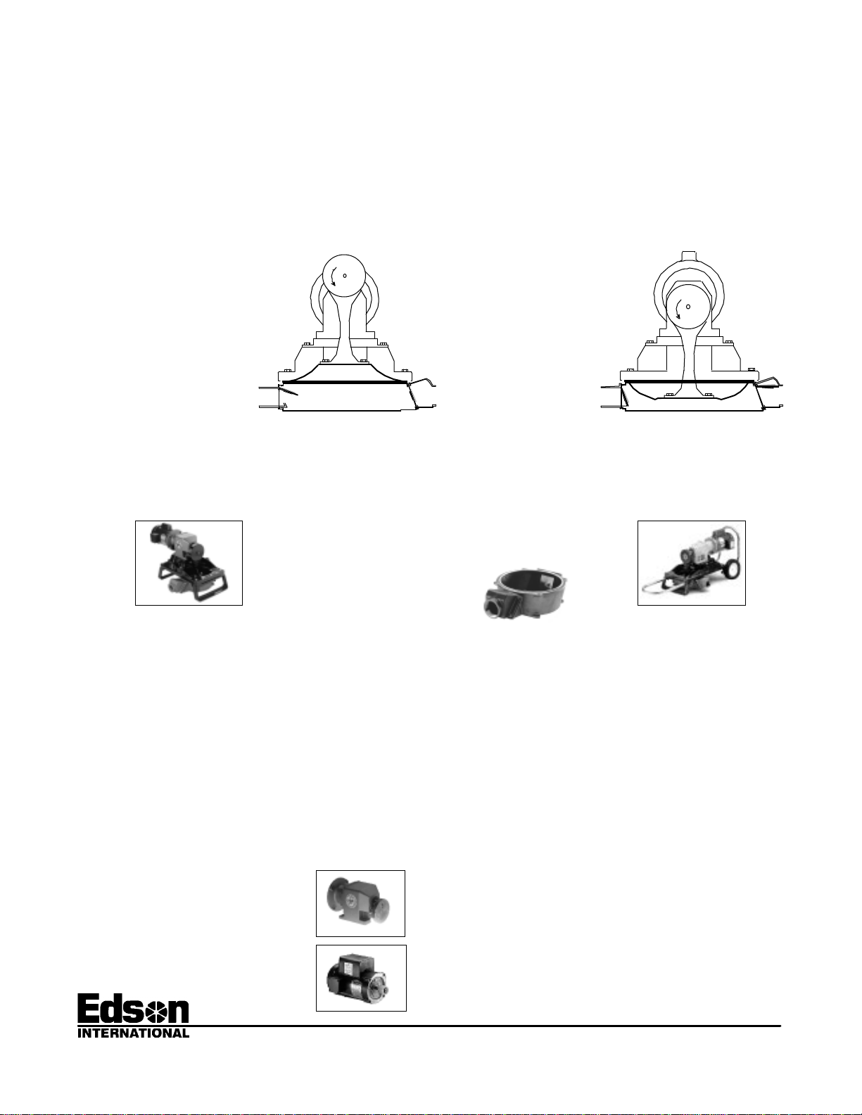
lKeepThePumpHorizontal-Thepumpisdesignedtobeinstalledonarelativelyhorizontal
surface.Ifthe mounting surface is not horizontal, the discharge should always be higher than
the inlet. If not installed accordingly the check valves will not work. The pump base can be
rotated 1800. See Fig 3
Installation Guidelines
Eccentric Grease
Fitting
7/16”
3/8”
5/16”
Discharge
3/8” 5/16”
7/16”
Fig.1
OK OK
Fig.2
Discharge Inlet
OK
Discharge
Inlet Discharge
Inlet
OK
Fig.3
WARNING
Factory Installed Motors Do Not Come Wired.
Itistheresponsibilityof the purchaser to have the electricalserviceinstalledbya
licencedelectricianinaccordancewith the power requirements of the motor,the
electricalservice available and local electricalcodes.
Failure to have the electricity installed correctly will result in damage to
the pump and potential bodily injury, loss of life and property damage
from electrical shock and fire.
Page3Installation

146 DUCHAINE BLVD., NEW BEDFORD, MA. 02745-1292 TEL. 508-995-9711 FAX 508-995-5021 E-MAIL pumps@edsonintl.com
P-98-120E pg.4
Important Plumbing Do & Don’ts
lDO NOT SHUT OFF DISCHARGE WHEN THE
PUMP IS RUNNING. See Fig 4 - Do not place the
pump in a situation were the discharge line will be
closed while the pump is running.
BECAUSE the Edson pump is a positive
displacement pump and it will continue to try to
pump liquid through a closed line. The pressure
created will cause damage to the pump.
lDISCHARGEFITTINGS, PIPEANDHOSE
SHOULD ALL BE THE SAME SIZE AND NEVER
BE SMALLER THAN THE INLET. See Fig. 5
BECAUSE a smaller discharge line increases
work for the pump and increases the possibility
ofclogging.
lDO NOT INSTALL THE PUMP AND PLUMBING
SO AIR WILL BE TRAPPED. See Fig. 6
BECAUSE trapped air can completely restrict the
flow or at the least require more work from the
pump resulting in early diaphragm failure. Install
pump and plumbing so any air introduced into the
plumbing will not be trapped but flow naturally
through liquid and out of the system.
lSHOULDNOTINSTALLPUMPWITH POSITIVE
HEAD ON THE INLET See Fig. 7 - Under
standard operating guidelines the pump should
be above the liquid it is being used to transfer.
BECAUSE of the flow through check valves,
stopping the pump will not stop the liquid from
flowing. Under the force of gravity liquid will pass
right through a diaphragm pump. Also consider a
diaphragm pump can not control a siphon
condition. They are used many times to start one.
Self Priming:
The Bone Dry Pump will develop a dry start vacuum of 10 to 12 inches of mercury, equal to a
height of approximately 12'. After the pump is primed the vacuum pressure will increase to 15”
hg or more. The self priming feature depends on:
lAn air tight suction line.
lThe flapper check valves sealing properly.
+=
Flapper
Check Valve
Valve
Seat
Fig.9
Fig.10
Good
Suction
Lift
Page4Plumbing
Use Only Non Collapsing Hose and Pipe
On the Inlet and Discharge of the Pump
Don’t
OK
Fig.7
Inlet
Discharge
DON'T
Fig.4
Discharge
1.5"ID
Inlet
2" ID
DON'T Fig.5
OK
Don’t
Fig.6
Air Tight
Against
Vacuum
Fig.8

146 DUCHAINE BLVD., NEW BEDFORD, MA. 02745-1292 TEL. 508-995-9711 FAX 508-995-5021 E-MAIL pumps@edsonintl.com
P-98-120E pg.5
Running The Pump Dry:
TheBoneDryPumpwillrundry indefinitely without damage.
Pumping Liquids with Suspended Solids:
lKEEPSOLIDS IN SUSPENSION - When the pump
is used to pump solid matter such as sludge at
the bottom of a tank or to dredge out a section of a
lagoonmakesurethe solids have enough liquid
mixed in to allow it to flow. Raking or stirring while
the pump is pumping will keep solids in
suspension.Ruleofthumbin pumping viscous
liquids or combinations of liquids with solids, "If It
Will Not Flow Through A Line Under Gravity, The
Pump Will Most Likely Not Pump It." See Fig.11
lFLAPPER CHECK VALVES AND SOLIDS -
Solids trapped under the check valves will
prevent self priming. This is likely to occure when
the pump is used in sewage or sump pump out
applications. Flushing with water will generally
clear out the solid matter. Installing secondary
clear flapper check valves right at the inlet and
discharge will improve the dry suction start
performance of the pump and make clearing the
valves easy. Order Edson Clear Check Valves
269CL-200 (2") or 269CL-150 (1.5"). See Fig.12
lPUMPING AT THE PROPER SPEED - When
pumping liquid with solids the speed may be too
slow to keep the solids and the liquid combined.
The solids will stop moving and begin to clog the
line. Pumping at a faster rate or decreasing the
hose size to increase velocity may be the solution.
CheckWithEdsonCustomerService.
lUSING A STRAINER ON THE INLET - If the
solids are too large they will block the inlet or get
stuck in the suction line. The end a suction hose
can become attached to a flat surface cutting off
all flow. Using an Edson strainer will prevent
these conditions. Order an Edson Shattedproof
Bronze Strainer 111BR - 200 or 111BR - 150
See Fig.13
lUSINGADISCHARGE LOOP - For sewageand
sump applications when the discharge drains
naturally down and away from the pump, installing
a 8” to 10” positive loop right on the discharge
port will improve the self priming feature. When
youstop pumping the loop traps some liquid
against the discharge valve improving the seal.
See Fig.14
Fig.11
Fig.12
Fig.13
Operation
UnionBall Valve
UnionCheck Valve
PVC Pipe Adapter
1
1
1
1
1
1
1
1
1
Fig.14
Page5Operation
146 DUCHAINE BLVD., NEW BEDFORD, MA. 02745-1292 TEL. 508-995-9711 FAX 508-995-5021 E-MAIL pumps@edsonintl.com
Pump Construction Information Is Defined By the Order # : Helpfulwhendetermining performance
limits and ordering replacement parts for your model pump.Example of Order # 120ELA 40 200
l1st Set - 120ELA specify the basic construction E=Electric,L=Skid Mounted, A= Aluminum
120ELB E=Electric, L =SkidMounted,B=Bronze
120EWA E=Electric, W=CartMounted, A=Aluminum
120EWB E=Electric, W=CartMounted, B=Bronze
l2ndSet-40specifyperformance.40=40 gpm, the nominal maximum volume for the pump
when ordered with the standard motor and reducer operating at full speed.
20 specify performance. 20=20 gpm, the nominal maximum volume for the pump
when ordered with the standard motor and reducer operating at half speed.
l3rd Set - 200 specify the size of the inlet 2” Male NPT & discharge as 2” Female NPT.
150 specify the size of the inlet 1 1/2” Male NPT & discharge as 1 1/2” Female NPT.
lOptions - Ordered as separate items. They are listed as order #’s starting with230 or231
followed by the part number and a description. Example, 230-A-1299=Motor Guard.
P-98-120E pg.6
How The Pump Works
lThe motor and gear reducer rotate the eccentric disk inside the eccentric housing.
lTheeccentrichousingraises and lowers the diaphragm.
lRaising the diaphragm creating a vacuum. See Fig.15
lThevacuumpulls the discharge valveassemblyclosed.
lAtmospheric pressure pushes liquid and/or air up the inlet plumbing to fill the vacuum.
lWhenthediaphragmisdriven down the air and liquid under the diaphragmiscompressed
closingtheinletcheckvalveandforcing the air and liquid out the discharge.Fig.16
lTheclosingoftheinletvalveassembly also prevents the liquid and air trapped in the
inletlinefromdropping back down (to atmosphere).
Inlet Valve Assembly:
opens into the pump
Discharge Valve Assembly:
closes and seals on the valve
seat that is part of the pump
base under the discharge
chamber.
SuctionStroke Discharge Stroke
Discharge Valve Assembly:
opens away from the pump
Inlet Valve Assembly:
closes and seals on the valve
seat that is part of the inlet
chamber.
Aluminum or Bronze is
the Metal of which the
Pump Chamber is Made
231 Options are motors and include:
A-1430 3/4hp, 60 hz, 1725 rpm, 110/220v, 1 ph, exproof
A-1429 3/4hp, 60 hz, 1725 rpm, 220/440v, 3 ph, tefc
A-1431 3/4hp, 60 hz, 1725 rpm, 220/440v, 3 ph, exproof
A-1383 1/2hp, 60 hz, 1725 rpm, 220/440v, 3 ph, tefc
A-1424 1/2hp, 60 hz, 1725 rpm, 110/220v, 1 ph, exproof
A-1425 1/2hp, 60 hz, 1725 rpm, 220/440v, 3 ph, exproof
A-1557 3/4hp, 50 hz, 1425 rpm, 220/440v, 3 ph, exproof
A-1560 3/4hp, 50 hz, 1425 rpm, 220/440v, 3 ph, tefc
A-1500 3/4hp, 50 hz, 2850 rpm, 110/220v, 1 ph, exproof
A-1556 3/4hp, 50 hz, 2850 rpm, 220/440v, 3 ph, exproof
A-1559 3/4hp, 50 hz, 2850 rpm, 220/440v, 3 ph, tefc
A-1211 3/4hp, VARIABLE , 60/ 50 hz ,110v, 1 ph, tefc
A-1432 3/4hp, 12 volt, DC, tefc
A-1433 3/4hp, 24 volt, DC, tefc
A-1426 1/2hp, 12 volt, DC, tefc
PTO No Motor
230 Options include:
1130V Viton Rubber Diaphragm
A-1745 47 to 1 Ratio Gear Reducer
A-1744 57 to 1 Ratio Gear Reducer
A-1746 87 to 1 Ratio Gear Reducer
A-1299 Motor Guard
Reducerw/Eccentric
Motorw/Coupling
Fig.15 Fig.16
Fig.18
Fig.20
Fig.21
120EWA
120EWB
Fig.19
120ELA
120ELB
Fig.17
Page6Operation&Construction

146 DUCHAINE BLVD., NEW BEDFORD, MA. 02745-1292 TEL. 508-995-9711 FAX 508-995-5021 E-MAIL pumps@edsonintl.com
P-98-120E pg.7
Pump Speed: The proper speed depends on the application, what type of liquid is being pumped and the
head conditions. The following guidelines apply for this pump.
lMaximum Cycle Rate is 60 RPM on the output shaft of the gear reducer.
lThe higher the viscosity the slower the pump. Viscous liquids need time to respond to
pumpingpressures.
l11/2”IDplumbingrequires pump speeds under 45 RPM.
lSmall suction lines under 1 1/2” ID require speeds under 20 RPM.
lThehigherthebackpressuretheslower the pump RPM.
Maintenance
Diaphragm: Edson 120 Pumps use Elastomer Diaphragm and Flapper Valves. Over time these parts
wear and need to be replacement. The ability to easily and quickly replace these inexpensive
parts is one of the major advantages of an Edson diaphragm pumps. Edson has packaged these
parts as Spares Kits. See the parts list for the order #s.
lChange the diaphragm as required. See Fig. 22
lInspection and testing on a regular basis is recommended. For continuous duty application,
inspect the pump daily until a life pattern is established.
lLook for leaks, cracks or splits on the surface of the diaphragm.
lLife expectancy is directly related to head conditions, run time and diaphragm material. The
higherthe suction and discharge pressures the shorter the life.
Warning
Lock Out Electrical Service or Unplug the Pump Electrical Line
Before Performing Any Service.
Failure to Do So Will Result In Bodily Injury
Valve Assemblies & The Valve Seats: The sealing of the flapper valves are what makes the diaphragm
pump work. If the valves are not sealing properly, the pump will not be performing to full potential
or may not be pumping at all. The valves tend to last longer than the diaphragm. When you
change the diaphragm inspect the valves for cracks and delamination and the valve seats for
pitting and any build up that will prevent the valve rubber from sealing effectively. Testing the
pump is the best way to evaluate performance.
lChange the valve assemblies as required. See Fig. 23
lInspection and testing on a regular bases is recommended. For continuous duty application,
inspect the pump daily until a life pattern is established.
lSee Pump Performance Tests (Page 8).
Step 1. Unbolt the Inlet and the
Discharge Chamber.
Step 2. Inspect Valve Seats.
Surfaces should be smooth,
flat and free of foreign matter.
Step 3. Resurface, if neces-
sary. Use a flat belt sander or
medium grade emery cloth
wrapped on a flat piece of
wood. It is important that the
valve seat area remains flat.
Step 4. Install New Valves.
Insure Valve Weight Screws
are Tight and Valves are
Oriented Properly.
Fig.23
Discharge
Inlet
Valve
Assembly
Valve
Seat
Valve
Assembly
Valve
Seat
Valve
Weight
Screws
Important:
Eccentricstaysconnectedto thereducer.
LowerStandardmustbe installedwith it’ssharp
edgeawayfrom thebottom of thediaphragm
ToolsRequired:
9/16”Socket Wrench with a 6"Extension
(2) 7/16” Box Wrench
Step 3. Reverse steps 1 & 2
to reassemble pump with new
diaphragm and the 2 sealing
washers on the 3/8” bolts.
Step 1. Unbolt Pump Base from
PumpFrame with 7/16” wrench. Step 2. Unbolt the Diaphragm
from the Eccentric Housing and
Lower Standard (STAINLESS STEEL
BACKING PLATE) with9/16” socket.
Fig.22
Page7Maintenance

146 DUCHAINE BLVD., NEW BEDFORD, MA. 02745-1292 TEL. 508-995-9711 FAX 508-995-5021 E-MAIL pumps@edsonintl.com
lVolume Test -Tests overall performance of the pump installation.
1.Use a container with a known capacity of at least 2 gallons.
2.Empty the container using the suction side of the pump or fill it from the discharge.
When using the fill test make sure the pump is fully primed before filling the container.
3.Use a watch to record the time it takes. Repeat the test at least twice.
4.Establish GPM rate. Example 1: It took 10 seconds to fill a 5 gallon container. The
GPM rate is 30 Gallons Per Minute.(60 seconds divided by 10 seconds times 5 gal.)
Example 2: It took 10 seconds to empty a 2 gallon container. The GPM rate is 12
Gallons Per Minute.(60 seconds divided by 10 seconds times 2 gal.)
5.Record the cycle speed of the pump. Know the head conditions of your test and
comparetheresultsofyourtestwith the volume of the appropriate Volume Chart
on page 2. Every installation is different so use the charts as a guideline.
6.Example 1: The “fill test” at 30 GPM. The diaphragm is going up and down at 56
cycles per minute. The pump is approximately 6 ft. above the liquid. I disconnected the
installation discharge line and replaced it with a 3 ft. length of 2” hose so I could do the
fill test. Using the 56 cycle per minute Volume Chart from page 2, I know that at a
suction height of 5 ft. and a discharge height of between 0 and 5 ft. I should get
approximately 30 GPM. The installation is performing within the guidelines.
6.Example 2: The “empty test” at 12 GPM. The diaphragm is going up and down at 30
cycles per minute. The pump was approximately 5 ft. above the 2 gal. container and
the discharge line goes up 4 ft. From the 30 cycle per minute Volume Chart on page
2, I know that with a suction height of 5 ft. and a discharge height of 0 to 5 ft. I
should get approximately 17 GPM. The installation is performing below the
guidelines. See the Trouble Shooting section of this manual.
lPressure Gauge Test - Tests the performance of the suction valve and valve seat.
1.Attach a 5’ length of non-collapsing hose or pipe with a 0 to 15 psi gauge installed
to the outlet of the pump. Make sure the line is completely sealed and air tight.
2.Turn on the pump and let it run till the gauge stabilizes. Record the reading.
3.If the suction valve is working properly the gage should build and pulse at 6 to 7 psi.
and when the pump is stopped the pressure may hold or slowly returns to 0.
4.If you do not get any pressure reading or if the gauge does not get to 4 psi and drops
off to 0 as soon as the pump stops, clean or replace the suction valve and clean or
resurface the valve seat as appropriate. See Maintenance/Valve Assemblies pg.7
lManual Test - Testing the pump valves and valve seats without the use of a gauge.
1.Removeallfittingsfromtheinletanddischargeofthepump.
2.Turn on the pump.
3.Putyourhandovertheinlet.If the discharge valve is working properly, you shouldfeela
verystrongpulsingsuction.Thepulsingcoincides with the raising and loweringof the
diaphragm. If you do not feel any suction, do the same thing again and listen for
airbeingsuckedinaroundthediaphragm. If you hear air movement, inspect for loose
bolts or worn diaphragm. If you hear no air movement, remove the discharge
chamber and inspect the valve assembly and valve seat. Clean or replace the valve
and clean or resurface the valve seat as appropriate.
4.Press your hand over the discharge. If the inlet valve is sealing properly, the
pressure of the pump down stroke should push your hand away. If it does not and the
air is forced out the inlet remove the inlet chamber and inspect the valve assembly
and valve seat. Clean or replace the valve and clean or resurface the valve seat as
appropriate. See Maintenance/Valve Assemblies pg.7
lVacuum Gauge Test - Tests the performance of the discharge valve and valve seat.
1.Attach a 5’ length of non-collapsing hose or pipe with a vacuum gauge installed
to the inlet of the pump. Make sure the line is completely sealed and air tight.
2.Turn on the pump and let it run till the gauge stabilizes. Record the reading.
3.Turn offthepumpand watch the gauge.
4.Ifthedischargeisworkingproperlythe gauge should build and hold at 10” to 12”hg.
Do not be concerned if the vacuum pressure slowly returns to 0 within a minute or so.
5.If you do not get any vacuum reading or if the gauge does not get to 10” hg and drops
off to 0 as soon as the pump stops, do the same thing again. Listen for air being
suckedinaroundthediaphragm.Ifyouhearairmovement,inspectforlooseboltsor
worn diaphragm. If you hear no air movement, remove the discharge chamber and
inspectthevalve assembly and valveseat.Cleanor replace the valveandcleanor
resurface the valve seat as appropriate. See Maintenance/Valve Assemblies pg.7
P-98-120E pg. 8
Pump Performance Tests:
Page8 PerformanceTest

146 DUCHAINE BLVD., NEW BEDFORD, MA. 02745-1292 TEL. 508-995-9711 FAX 508-995-5021 E-MAIL pumps@edsonintl.com
Trouble Shooting
P-98-120E pg.9
5.Problem
Pumpbaseand/orlines
keep filling with solids
PossibleCauses
a. Line velocity is too slow to
keep the solids in suspen
sion.
b. The percent of solids is too
high.
Action
Speedingupthe pump will help increase the
velocity. Using a strainer can reduce the size and
percent of solids. Diluting the slurry by increasing
the amount of liquid or by increasing the agitation
ofthemixmaysolve the problem. Review
PumpingLiquidswithSuspendedSolidspage5
4.Problem
Diaphragmis wearing
outmuchearlierthan
expected.
PossibleCauses
a. Liquid being pumped is not
compatible with the
diaphragm material.
b. Discharge and/or suction
back pressure too high.
Action
Consultachemicalresistancechart,reviewthe
Installation Guidelines pages 2 to 5. Call Edson
CustomerService.
3.Problem
Motorisrunningbut
reducerisnot moving
PossibleCause
a. Reducer Coupling hascome
lose on the motor shaft.
Action
Removethemotor and reposition and securethe
coupling to the motor shaft. See parts diagram
forpositioninginstructions.
2.Problem
Motor is starting. PossibleCauses
a. Electrical Supply or wiring
problem.
b. Motor worn out.
Action
Check electrical switch and/or circuit breaker. If
not familiar with electrical problems, call an
electrician. If circuit breaker is tripped for no
apparent reason or the motor is worn out
way too soon, check the pump and the line
for a blockage or restriction. Review the
Performance Specifications and installation
Guidelines pages 2 to 5.
1.Problem
Pumpisrunning,liquid
isnotmoving.
PossibleCauses
a. Suction line is blocked.
b. Suction line has air leak
betweenliquidandinletofthe
pump.
c. Discharge and/orsuction
valvesare notworking.
d. Diaphragm has a leak.
e. Discharge or suction line is
to high.
Action
If the cause is not obvious, isolate the source.
Disconnecttheinletanddischarge plumbing from
thepumpandperformtheManualTest page 8. If
the cause is not in the pump check for a block or
an air leak in the suction line. Suction air leaks
can be cumulative and can be as simple as one
ortwofittings not being sealed properly. Review
Plumbing pages 4 to 5
The Edson Electric Powered Diaphragm Pump is very simple and problems are isolated to only the
followingcomponents:
l The Motor & Gear Reducer
l The Gear Reducer and Eccentric
l The Diaphragm and Valves
l Suction and Discharge Plumbing
Eccentric: A disk called an eccentric is pressed onto the output shaft of the gear reducer. As it rotates
inside the bronze eccentric housing the diaphragm is raised and lowered. This assembly needs to
be greased with any good gear grease. Edson applies Mobil Grease HP Multiporpose
Premium Grease during the assembly of the pump. Failure to grease this part will result in early
wear.
Page9 Trouble Shooting

146 DUCHAINE BLVD., NEW BEDFORD, MA. 02745-1292 TEL. 508-995-9711 FAX 508-995-5021 E-MAIL pumps@edsonintl.com
Page10Parts Drawing
13 14
15
16
17
18
19
16 18
P-98-120E pg.10
Parts
MODELS 120E
BaseAssembly
28
29
30
32
31 28
30
Spares Kit 33
1
2345678
9
12
20
23
24 25
26
27
22
21
11
10

146 DUCHAINE BLVD., NEW BEDFORD, MA. 02745-1292 TEL. 508-995-9711 FAX 508-995-5021 E-MAIL pumps@edsonintl.com
Parts List 120ELA-40-150
Edson Order # Description
120ELA-40-150 Bone Dry Electric Diaphragm Pump, Skid Mounted, Aluminum,
1.5" MNPT Inlet and 1.5" FNPT Discharge
Key # Edson Order # Description (nsn number if there is one) Qty
1 161-A-161 3/4 HP, 1725 RPM, 120/240V, 60HZ, TEFC, Electric Motor 1
(6105013331595)(This is the standard motor. An optional motor may
have been installed on the pump. Check legend plate on the motor.)
2 161-A-1811-2 Motor Coupling for A-1743 Reducer (included with Reducer key #3) 1
3 161-A-1743 31 to 1 C-Face Gear reducer and coupling (includes 1
Motor Coupling & Eccentric Disk key #s 2 & 4)
4 161-A-168 Eccentric Disk (included with Reducer key # 3) 1
5 161-A-1161 Snap Ring (included with Eccentric Housing key #6) 1
6 161-A-1213 Eccentric Housing With Snap Ring (includes Zerk Fitting 1
& Snap Ring key #s 6, 7, 8)
7 161-A-150 Zerk Grease Fitting (included with Eccentric Housing key #6) 1
8 161-A-399 Zerk Fitting Dust Cap (included with Eccentric Housing key #6) 1
9 3/8-16X1.25" HHCS Stainless Hex Head Cap Screws 2
10 160-A-1200 Sealing Washers (5310013938514) Not Shown 2
11 113H-0 Diaphragm (4820013935286) 1
12 160-A-906 Lower Standard (4320013331830) 1
13 3/8"-16X1" HHCS Stainless Hex Head Cap Screws 8
14 5/16"-18X1.25"HHCS Stainless Hex Head Cap Screws 4
15 161-C-583 Reducer Mounting Adapter Plate 1
16 3/8"-16X2.5" HHCS Stainless Hex Head Cap Screws 4
17 161-D-69 Pump Frame 1
18 161-C-389 Pump Leg 2
19 1/4"-20X1.5 HHCS Stainless Hex Head Cap Screws with Washers 4
20 161-A-1299 Motor Guard (Optional part installed only when ordered) 0
21 161-A-164 Axle Hanger 0
22 161-A-166 Wheel 0
23 161-A-143 Pal Nut 0
24 161-A-165 Stainless Axle 0
25 3/8"-16X4" HHCS Stainless Hex Head Cap Screws with Nuts and Washers 0
26 3/8"-16X3" HHCS Stainless Hex Head Cap Screws with Nuts and Washers 0
27 161-A-147 Pump Handle 0
28 1/4"-20X1 HHCS Stainless Hex Head Cap Screws with Nuts and Washers 8
29 160-B-50A-150 Aluminum Discharge Chamber 1.5" 1
30 160-G-107 Inlet/Discharge Valve Assembly (4320013235967) 2
31 160-C-186 Aluminum Side Inlet Pump Base 1
32 160-B-324A Aluminum Suction Chamber 1.5" 1
33 114H-117-120 Bone Dry Spares Kit (4320013433658)
Includes: Qty 1 - 113H-0 DIAPHRAGM (key # 3)
Qty 2 - 160-G-107 (key #27)
Qty 2 - 160-A-1200 (key # 32)

146 DUCHAINE BLVD., NEW BEDFORD, MA. 02745-1292 TEL. 508-995-9711 FAX 508-995-5021 E-MAIL pumps@edsonintl.com
Parts List 120EWA-40-150
Edson Order # Description
120EWA-40-150 Bone Dry Electric Diaphragm Pump, Cart Mounted, Aluminum,
1.5" MNPT Inlet and 1.5" FNPT Discharge
Key # Edson Order # Description (nsn number if there is one) Qty
1 161-A-161 3/4 HP, 1725 RPM, 120/240V, 60HZ, TEFC, Electric Motor 1
(6105013331595)(This is the standard motor. An optional motor may
have been installed on the pump. Check legend plate on the motor.)
2 161-A-1811-2 Motor Coupling for A-1743 Reducer (included with Reducer key #3) 1
3 161-A-1743 31 to 1 C-Face Gear reducer and coupling (includes 1
Motor Coupling & Eccentric Disk key #s 2 & 4)
4 161-A-168 Eccentric Disk (included with Reducer key # 3) 1
5 161-A-1161 Snap Ring (included with Eccentric Housing key #6) 1
6 161-A-1213 Eccentric Housing With Snap Ring (includes Zerk Fitting 1
& Snap Ring key #s 6, 7, 8)
7 161-A-150 Zerk Grease Fitting (included with Eccentric Housing key #6) 1
8 161-A-399 Zerk Fitting Dust Cap (included with Eccentric Housing key #6) 1
9 3/8-16X1.25" HHCS Stainless Hex Head Cap Screws 2
10 160-A-1200 Sealing Washers (5310013938514) Not Shown 2
11 113H-0 Diaphragm (4820013935286) 1
12 160-A-906 Lower Standard (4320013331830) 1
13 3/8"-16X1" HHCS Stainless Hex Head Cap Screws 8
14 5/16"-18X1.25"HHCS Stainless Hex Head Cap Screws 4
15 161-C-583 Reducer Mounting Adapter Plate 1
16 3/8"-16X2.5" HHCS Stainless Hex Head Cap Screws 0
17 161-D-69 Pump Frame 1
18 161-C-389 Pump Leg 1
19 1/4"-20X1.5 HHCS Stainless Hex Head Cap Screws with Washers 4
20 161-A-1299 Motor Guard (Optional part installed only when ordered) 0
21 161-A-164 Axle Hanger 2
22 161-A-166 Wheel 2
23 161-A-143 Pal Nut 2
24 161-A-165 Stainless Axle 1
25 3/8"-16X4" HHCS Stainless Hex Head Cap Screws with Nuts and Washers 2
26 3/8"-16X3" HHCS Stainless Hex Head Cap Screws with Nuts and Washers 2
27 161-A-147 Pump Handle 1
28 1/4"-20X1 HHCS Stainless Hex Head Cap Screws with Nuts and Washers 8
29 160-B-50A-150 Aluminum Discharge Chamber 1.5" 1
30 160-G-107 Inlet/Discharge Valve Assembly (4320013235967) 2
31 160-C-186 Aluminum Side Inlet Pump Base 1
32 160-B-324A Aluminum Suction Chamber 1.5" 1
33 114H-117-120 Bone Dry Spares Kit (4320013433658)
Includes: Qty 1 - 113H-0 DIAPHRAGM (key # 3)
Qty 2 - 160-G-107 (key #27)
Qty 2 - 160-A-1200 (key # 32)

146 DUCHAINE BLVD., NEW BEDFORD, MA. 02745-1292 TEL. 508-995-9711 FAX 508-995-5021 E-MAIL pumps@edsonintl.com
Parts List 120ELA-40-200
Edson Order # Description
120ELA-40-200 Bone Dry Electric Diaphragm Pump, Skid Mounted, Aluminum,
2" MNPT Inlet and 2" FNPT Discharge
Key # Edson Order # Description (nsn number if there is one) Qty
1 161-A-161 3/4 HP, 1725 RPM, 120/240V, 60HZ, TEFC, Electric Motor 1
(6105013331595)(This is the standard motor. An optional motor may
have been installed on the pump. Check legend plate on the motor.)
2 161-A-1811-2 Motor Coupling for A-1743 Reducer (included with Reducer key #3) 1
3 161-A-1743 31 to 1 C-Face Gear reducer and coupling (includes 1
Motor Coupling & Eccentric Disk key #s 2 & 4)
4 161-A-168 Eccentric Disk (included with Reducer key # 3) 1
5 161-A-1161 Snap Ring (included with Eccentric Housing key #6) 1
6 161-A-1213 Eccentric Housing With Snap Ring (includes Zerk Fitting 1
& Snap Ring key #s 6, 7, 8)
7 161-A-150 Zerk Grease Fitting (included with Eccentric Housing key #6) 1
8 161-A-399 Zerk Fitting Dust Cap (included with Eccentric Housing key #6) 1
9 3/8-16X1.25" HHCS Stainless Hex Head Cap Screws 2
10 160-A-1200 Sealing Washers (5310013938514) Not Shown 2
11 113H-0 Diaphragm (4820013935286) 1
12 160-A-906 Lower Standard (4320013331830) 1
13 3/8"-16X1" HHCS Stainless Hex Head Cap Screws 8
14 5/16"-18X1.25"HHCS Stainless Hex Head Cap Screws 4
15 161-C-583 Reducer Mounting Adapter Plate 1
16 3/8"-16X2.5" HHCS Stainless Hex Head Cap Screws 4
17 161-D-69 Pump Frame 1
18 161-C-389 Pump Leg 2
19 1/4"-20X1.5 HHCS Stainless Hex Head Cap Screws with Washers 4
20 161-A-1299 Motor Guard (Optional part installed only when ordered) 0
21 161-A-164 Axle Hanger 0
22 161-A-166 Wheel 0
23 161-A-143 Pal Nut 0
24 161-A-165 Stainless Axle 0
25 3/8"-16X4" HHCS Stainless Hex Head Cap Screws with Nuts and Washers 0
26 3/8"-16X3" HHCS Stainless Hex Head Cap Screws with Nuts and Washers 0
27 161-A-147 Pump Handle 0
28 1/4"-20X1 HHCS Stainless Hex Head Cap Screws with Nuts and Washers 8
29 160-B-50A-200 Aluminum Discharge Chamber 2" 1
30 160-G-107 Inlet/Discharge Valve Assembly (4320013235967) 2
31 160-C-186 Aluminum Side Inlet Pump Base 1
32 160-B-68A Aluminum Suction Chamber 2" 1
33 114H-117-120 Bone Dry Spares Kit (4320013433658)
Includes: Qty 1 - 113H-0 DIAPHRAGM (key # 3)
Qty 2 - 160-G-107 (key #27)
Qty 2 - 160-A-1200 (key # 32)

146 DUCHAINE BLVD., NEW BEDFORD, MA. 02745-1292 TEL. 508-995-9711 FAX 508-995-5021 E-MAIL pumps@edsonintl.com
Parts List 120EWA-40-200
Edson Order # Description
120EWA-40-200 Bone Dry Electric Diaphragm Pump, Cart Mounted, Aluminum,
2" MNPT Inlet and 2" FNPT Discharge
Key # Edson Order # Description (nsn number if there is one) Qty
1 161-A-161 3/4 HP, 1725 RPM, 120/240V, 60HZ, TEFC, Electric Motor 1
(6105013331595)(This is the standard motor. An optional motor may
have been installed on the pump. Check legend plate on the motor.)
2 161-A-1811-2 Motor Coupling for A-1743 Reducer (included with Reducer key #3) 1
3 161-A-1743 31 to 1 C-Face Gear reducer and coupling (includes 1
Motor Coupling & Eccentric Disk key #s 2 & 4)
4 161-A-168 Eccentric Disk (included with Reducer key # 3) 1
5 161-A-1161 Snap Ring (included with Eccentric Housing key #6) 1
6 161-A-1213 Eccentric Housing With Snap Ring (includes Zerk Fitting 1
& Snap Ring key #s 6, 7, 8)
7 161-A-150 Zerk Grease Fitting (included with Eccentric Housing key #6) 1
8 161-A-399 Zerk Fitting Dust Cap (included with Eccentric Housing key #6) 1
9 3/8-16X1.25" HHCS Stainless Hex Head Cap Screws 2
10 160-A-1200 Sealing Washers (5310013938514) Not Shown 2
11 113H-0 Diaphragm (4820013935286) 1
12 160-A-906 Lower Standard (4320013331830) 1
13 3/8"-16X1" HHCS Stainless Hex Head Cap Screws 8
14 5/16"-18X1.25"HHCS Stainless Hex Head Cap Screws 4
15 161-C-583 Reducer Mounting Adapter Plate 1
16 3/8"-16X2.5" HHCS Stainless Hex Head Cap Screws 0
17 161-D-69 Pump Frame 1
18 161-C-389 Pump Leg 1
19 1/4"-20X1.5 HHCS Stainless Hex Head Cap Screws with Washers 4
20 161-A-1299 Motor Guard (Optional part installed only when ordered) 0
21 161-A-164 Axle Hanger 2
22 161-A-166 Wheel 2
23 161-A-143 Pal Nut 2
24 161-A-165 Stainless Axle 1
25 3/8"-16X4" HHCS Stainless Hex Head Cap Screws with Nuts and Washers 2
26 3/8"-16X3" HHCS Stainless Hex Head Cap Screws with Nuts and Washers 2
27 161-A-147 Pump Handle 1
28 1/4"-20X1 HHCS Stainless Hex Head Cap Screws with Nuts and Washers 8
29 160-B-50A-200 Aluminum Discharge Chamber 2" 1
30 160-G-107 Inlet/Discharge Valve Assembly (4320013235967) 2
31 160-C-186 Aluminum Side Inlet Pump Base 1
32 160-B-68A Aluminum Suction Chamber 2" 1
33 114H-117-120 Bone Dry Spares Kit (4320013433658)
Includes: Qty 1 - 113H-0 DIAPHRAGM (key # 3)
Qty 2 - 160-G-107 (key #27)
Qty 2 - 160-A-1200 (key # 32)

146 DUCHAINE BLVD., NEW BEDFORD, MA. 02745-1292 TEL. 508-995-9711 FAX 508-995-5021 E-MAIL pumps@edsonintl.com
Parts List 120ELB-40-150
Edson Order # Description
120ELB-40-150 Bone Dry Electric Diaphragm Pump, Skid Mounted, Bronze,
1.5" MNPT Inlet and 1.5" FNPT Discharge
Key # Edson Order # Description (nsn number if there is one) Qty
1 161-A-161 3/4 HP, 1725 RPM, 120/240V, 60HZ, TEFC, Electric Motor 1
(6105013331595)(This is the standard motor. An optional motor may
have been installed on the pump. Check legend plate on the motor.)
2 161-A-1811-2 Motor Coupling for A-1743 Reducer (included with Reducer key #3) 1
3 161-A-1743 31 to 1 C-Face Gear reducer and coupling (includes 1
Motor Coupling & Eccentric Disk key #s 2 & 4)
4 161-A-168 Eccentric Disk (included with Reducer key # 3) 1
5 161-A-1161 Snap Ring (included with Eccentric Housing key #6) 1
6 161-A-1213 Eccentric Housing With Snap Ring (includes Zerk Fitting 1
& Snap Ring key #s 6, 7, 8)
7 161-A-150 Zerk Grease Fitting (included with Eccentric Housing key #6) 1
8 161-A-399 Zerk Fitting Dust Cap (included with Eccentric Housing key #6) 1
9 3/8-16X1.25" HHCS Stainless Hex Head Cap Screws 2
10 160-A-1200 Sealing Washers (5310013938514) Not Shown 2
11 113H-0 Diaphragm (4820013935286) 1
12 160-A-906 Lower Standard (4320013331830) 1
13 3/8"-16X1" HHCS Stainless Hex Head Cap Screws 8
14 5/16"-18X1.25"HHCS Stainless Hex Head Cap Screws 4
15 161-C-583 Reducer Mounting Adapter Plate 1
16 3/8"-16X2.5" HHCS Stainless Hex Head Cap Screws 4
17 161-D-69 Pump Frame 1
18 161-C-389 Pump Leg 2
19 1/4"-20X1.5 HHCS Stainless Hex Head Cap Screws with Washers 4
20 161-A-1299 Motor Guard (Optional part installed only when ordered) 0
21 161-A-164 Axle Hanger 0
22 161-A-166 Wheel 0
23 161-A-143 Pal Nut 0
24 161-A-165 Stainless Axle 0
25 3/8"-16X4" HHCS Stainless Hex Head Cap Screws with Nuts and Washers 0
26 3/8"-16X3" HHCS Stainless Hex Head Cap Screws with Nuts and Washers 0
27 161-A-147 Pump Handle 0
28 1/4"-20X1 HHCS Stainless Hex Head Cap Screws with Nuts and Washers 8
29 160-B-50B-150 Bronze Discharge Chamber 1.5" 1
30 160-G-107 Inlet/Discharge Valve Assembly (4320013235967) 2
31 160-C-298 Bronze Side Inlet Pump Base 1
32 160-B-324B Bronze Suction Chamber 1.5" 1
33 114H-117-120 Bone Dry Spares Kit (4320013433658)
Includes: Qty 1 - 113H-0 DIAPHRAGM (key # 3)
Qty 2 - 160-G-107 (key #27)
Qty 2 - 160-A-1200 (key # 32)

146 DUCHAINE BLVD., NEW BEDFORD, MA. 02745-1292 TEL. 508-995-9711 FAX 508-995-5021 E-MAIL pumps@edsonintl.com
Parts List 120EWB-40-150
Edson Order # Description
120EWB-40-150 Bone Dry Electric Diaphragm Pump, Cart Mounted, Bronze,
1.5" MNPT Inlet and 1.5" FNPT Discharge
Key # Edson Order # Description (nsn number if there is one) Qty
1 161-A-161 3/4 HP, 1725 RPM, 120/240V, 60HZ, TEFC, Electric Motor 1
(6105013331595)(This is the standard motor. An optional motor may
have been installed on the pump. Check legend plate on the motor.)
2 161-A-1811-2 Motor Coupling for A-1743 Reducer (included with Reducer key #3) 1
3 161-A-1743 31 to 1 C-Face Gear reducer and coupling (includes 1
Motor Coupling & Eccentric Disk key #s 2 & 4)
4 161-A-168 Eccentric Disk (included with Reducer key # 3) 1
5 161-A-1161 Snap Ring (included with Eccentric Housing key #6) 1
6 161-A-1213 Eccentric Housing With Snap Ring (includes Zerk Fitting 1
& Snap Ring key #s 6, 7, 8)
7 161-A-150 Zerk Grease Fitting (included with Eccentric Housing key #6) 1
8 161-A-399 Zerk Fitting Dust Cap (included with Eccentric Housing key #6) 1
9 3/8-16X1.25" HHCS Stainless Hex Head Cap Screws 2
10 160-A-1200 Sealing Washers (5310013938514) Not Shown 2
11 113H-0 Diaphragm (4820013935286) 1
12 160-A-906 Lower Standard (4320013331830) 1
13 3/8"-16X1" HHCS Stainless Hex Head Cap Screws 8
14 5/16"-18X1.25"HHCS Stainless Hex Head Cap Screws 4
15 161-C-583 Reducer Mounting Adapter Plate 1
16 3/8"-16X2.5" HHCS Stainless Hex Head Cap Screws 0
17 161-D-69 Pump Frame 1
18 161-C-389 Pump Leg 1
19 1/4"-20X1.5 HHCS Stainless Hex Head Cap Screws with Washers 4
20 161-A-1299 Motor Guard (Optional part installed only when ordered) 0
21 161-A-164 Axle Hanger 2
22 161-A-166 Wheel 2
23 161-A-143 Pal Nut 2
24 161-A-165 Stainless Axle 1
25 3/8"-16X4" HHCS Stainless Hex Head Cap Screws with Nuts and Washers 2
26 3/8"-16X3" HHCS Stainless Hex Head Cap Screws with Nuts and Washers 2
27 161-A-147 Pump Handle 1
28 1/4"-20X1 HHCS Stainless Hex Head Cap Screws with Nuts and Washers 8
29 160-B-50B-150 Bronze Discharge Chamber 1.5" 1
30 160-G-107 Inlet/Discharge Valve Assembly (4320013235967) 2
31 160-C-298 Bronze Side Inlet Pump Base 1
32 160-B-324B Bronze Suction Chamber 1.5" 1
33 114H-117-120 Bone Dry Spares Kit (4320013433658)
Includes: Qty 1 - 113H-0 DIAPHRAGM (key # 3)
Qty 2 - 160-G-107 (key #27)
Qty 2 - 160-A-1200 (key # 32)

146 DUCHAINE BLVD., NEW BEDFORD, MA. 02745-1292 TEL. 508-995-9711 FAX 508-995-5021 E-MAIL pumps@edsonintl.com
Parts List 120ELB-40-200
Edson Order # Description
120ELB-40-200 Bone Dry Electric Diaphragm Pump, Skid Mounted, Bronze,
2" MNPT Inlet and 2" FNPT Discharge
Key # Edson Order # Description (nsn number if there is one) Qty
1 161-A-161 3/4 HP, 1725 RPM, 120/240V, 60HZ, TEFC, Electric Motor 1
(6105013331595)(This is the standard motor. An optional motor may
have been installed on the pump. Check legend plate on the motor.)
2 161-A-1811-2 Motor Coupling for A-1743 Reducer (included with Reducer key #3) 1
3 161-A-1743 31 to 1 C-Face Gear reducer and coupling (includes 1
Motor Coupling & Eccentric Disk key #s 2 & 4)
4 161-A-168 Eccentric Disk (included with Reducer key # 3) 1
5 161-A-1161 Snap Ring (included with Eccentric Housing key #6) 1
6 161-A-1213 Eccentric Housing With Snap Ring (includes Zerk Fitting 1
& Snap Ring key #s 6, 7, 8)
7 161-A-150 Zerk Grease Fitting (included with Eccentric Housing key #6) 1
8 161-A-399 Zerk Fitting Dust Cap (included with Eccentric Housing key #6) 1
9 3/8-16X1.25" HHCS Stainless Hex Head Cap Screws 2
10 160-A-1200 Sealing Washers (5310013938514) Not Shown 2
11 113H-0 Diaphragm (4820013935286) 1
12 160-A-906 Lower Standard (4320013331830) 1
13 3/8"-16X1" HHCS Stainless Hex Head Cap Screws 8
14 5/16"-18X1.25"HHCS Stainless Hex Head Cap Screws 4
15 161-C-583 Reducer Mounting Adapter Plate 1
16 3/8"-16X2.5" HHCS Stainless Hex Head Cap Screws 4
17 161-D-69 Pump Frame 1
18 161-C-389 Pump Leg 2
19 1/4"-20X1.5 HHCS Stainless Hex Head Cap Screws with Washers 4
20 161-A-1299 Motor Guard (Optional part installed only when ordered) 0
21 161-A-164 Axle Hanger 0
22 161-A-166 Wheel 0
23 161-A-143 Pal Nut 0
24 161-A-165 Stainless Axle 0
25 3/8"-16X4" HHCS Stainless Hex Head Cap Screws with Nuts and Washers 0
26 3/8"-16X3" HHCS Stainless Hex Head Cap Screws with Nuts and Washers 0
27 161-A-147 Pump Handle 0
28 1/4"-20X1 HHCS Stainless Hex Head Cap Screws with Nuts and Washers 8
29 160-B-50B-200 Bronze Discharge Chamber 2" 1
30 160-G-107 Inlet/Discharge Valve Assembly (4320013235967) 2
31 160-C-298 Bronze Side Inlet Pump Base 1
32 160-B-68B Bronze Suction Chamber 2" 1
33 114H-117-120 Bone Dry Spares Kit (4320013433658)
Includes: Qty 1 - 113H-0 DIAPHRAGM (key # 3)
Qty 2 - 160-G-107 (key #27)
Qty 2 - 160-A-1200 (key # 32)

146 DUCHAINE BLVD., NEW BEDFORD, MA. 02745-1292 TEL. 508-995-9711 FAX 508-995-5021 E-MAIL pumps@edsonintl.com
Parts List 120EWB-40-200
Edson Order # Description
120EWB-40-200 Bone Dry Electric Diaphragm Pump, Cart Mounted, Bronze,
2" MNPT Inlet and 2" FNPT Discharge
Key # Edson Order # Description (nsn number if there is one) Qty
1 161-A-161 3/4 HP, 1725 RPM, 120/240V, 60HZ, TEFC, Electric Motor 1
(6105013331595)(This is the standard motor. An optional motor may
have been installed on the pump. Check legend plate on the motor.)
2 161-A-1811-2 Motor Coupling for A-1743 Reducer (included with Reducer key #3) 1
3 161-A-1743 31 to 1 C-Face Gear reducer and coupling (includes 1
Motor Coupling & Eccentric Disk key #s 2 & 4)
4 161-A-168 Eccentric Disk (included with Reducer key # 3) 1
5 161-A-1161 Snap Ring (included with Eccentric Housing key #6) 1
6 161-A-1213 Eccentric Housing With Snap Ring (includes Zerk Fitting 1
& Snap Ring key #s 6, 7, 8)
7 161-A-150 Zerk Grease Fitting (included with Eccentric Housing key #6) 1
8 161-A-399 Zerk Fitting Dust Cap (included with Eccentric Housing key #6) 1
9 3/8-16X1.25" HHCS Stainless Hex Head Cap Screws 2
10 160-A-1200 Sealing Washers (5310013938514) Not Shown 2
11 113H-0 Diaphragm (4820013935286) 1
12 160-A-906 Lower Standard (4320013331830) 1
13 3/8"-16X1" HHCS Stainless Hex Head Cap Screws 8
14 5/16"-18X1.25"HHCS Stainless Hex Head Cap Screws 4
15 161-C-583 Reducer Mounting Adapter Plate 1
16 3/8"-16X2.5" HHCS Stainless Hex Head Cap Screws 0
17 161-D-69 Pump Frame 1
18 161-C-389 Pump Leg 1
19 1/4"-20X1.5 HHCS Stainless Hex Head Cap Screws with Washers 4
20 161-A-1299 Motor Guard (Optional part installed only when ordered) 0
21 161-A-164 Axle Hanger 2
22 161-A-166 Wheel 2
23 161-A-143 Pal Nut 2
24 161-A-165 Stainless Axle 1
25 3/8"-16X4" HHCS Stainless Hex Head Cap Screws with Nuts and Washers 2
26 3/8"-16X3" HHCS Stainless Hex Head Cap Screws with Nuts and Washers 2
27 161-A-147 Pump Handle 1
28 1/4"-20X1 HHCS Stainless Hex Head Cap Screws with Nuts and Washers 8
29 160-B-50B-200 Bronze Discharge Chamber 2" 1
30 160-G-107 Inlet/Discharge Valve Assembly (4320013235967) 2
31 160-C-298 Bronze Side Inlet Pump Base 1
32 160-B-68B Bronze Suction Chamber 2" 1
33 114H-117-120 Bone Dry Spares Kit (4320013433658)
Includes: Qty 1 - 113H-0 DIAPHRAGM (key # 3)
Qty 2 - 160-G-107 (key #27)
Qty 2 - 160-A-1200 (key # 32)
This manual suits for next models
8
Table of contents
Other Edson Water Pump manuals


Popular Water Pump manuals by other brands

dosatron
dosatron D25ALN owner's manual

Stuart Turner
Stuart Turner Supersub 460A operating instructions

Barnes
Barnes 30MU Installation and operation manual

BVA Hydraulics
BVA Hydraulics P570FP instruction manual

Lincoln
Lincoln P502 installation instructions

GORMAN-RUPP
GORMAN-RUPP HO3/4A4-36DK PARTS LIST AND MAINTENANCE MANUAL

BJM Pumps
BJM Pumps XP-JX Series Installation, operation & maintenance manual

Grundfos
Grundfos Hydro Multi-B Installation and operating instructions

Pentair
Pentair Myers 3VX Series Installation and service manual

ASC
ASC SP010 instructions

U-Line
U-Line H-4377 manual

AC Infinity
AC Infinity AC-AUS21 user manual


