4
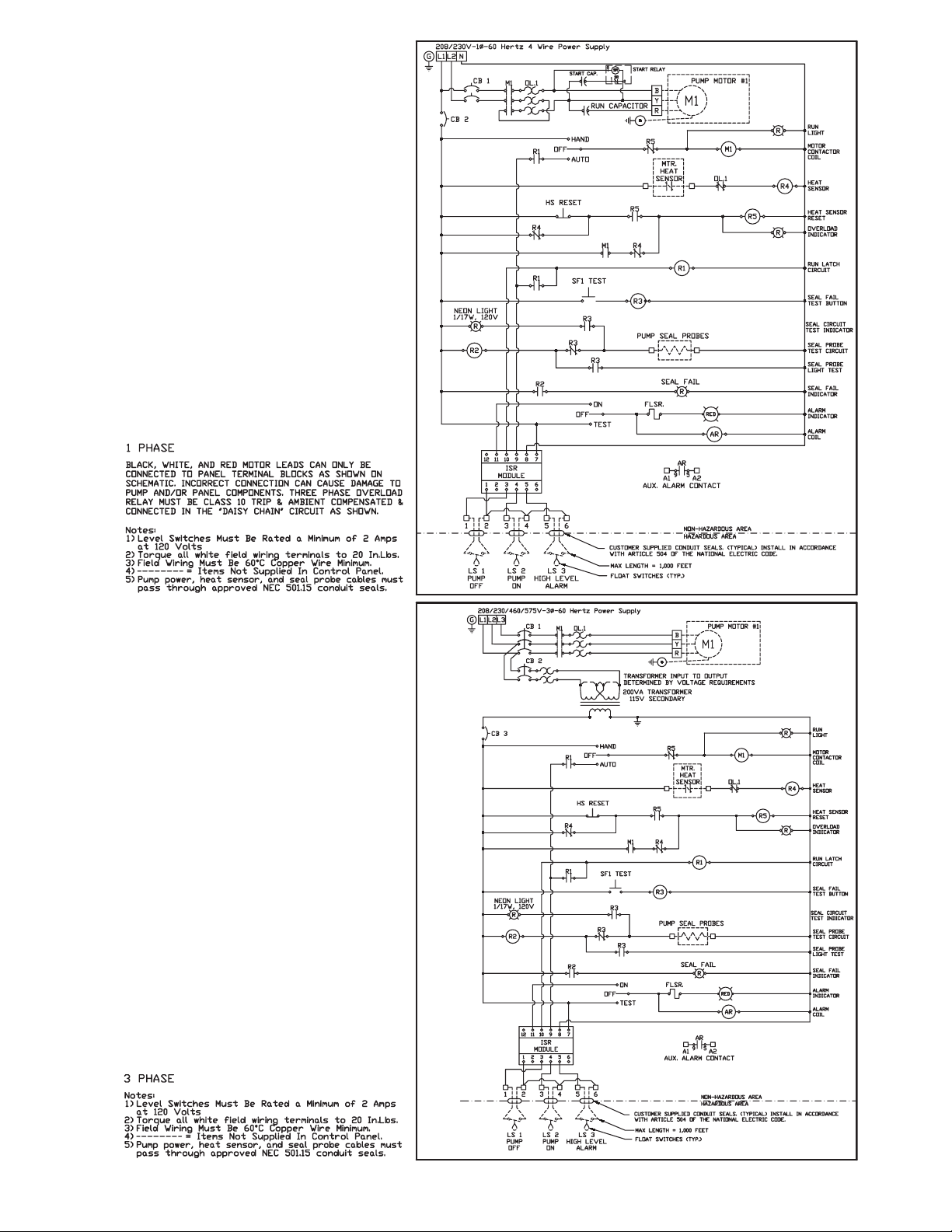
Electrical Motor Controls: All electrical controls and
motor starting equipment should be as specied in
these instructions. Consult factory for any acceptable
alternatives. For hazardous locations the controls and
control panel must be installed outside the hazardous
area, or approved hazardous location controls that are
intrinsically safe must be used.
Junction Box: If a junction box is used in a hazardous
location, it must be a hazardous location approved
type with hazardous location cord connectors. Wires
from the junction box must pass through a hazardous
location seal connector.
Level Sensing Controls: Intrinsically safe type oat
controls are recommended for all applications and
required for hazardous location service. An intrinsically
safe control panel relay will limit the current and voltage
to the level controls. A Myers®control panel can be
supplied with this type circuitry.
The oat level controls maintain the basin sewage water
level by controlling pump turn-on and turn-off levels.
The lower turn-off control should be set so that the
pump stops at approximately the top of the pump.
Consult the factory for any settings below this point.
The upper turn-on control should be set above the lower
turn-off control. The exact height between the two
controls is determined by the number of pump starts
desired and the depth of the basin. A maximum of 10
starts per hour should not be exceeded.
The override control is set at a specied height above
the upper turn-on control.
The alarm control is set about 6" to 12" above the
override control.
No control should be set above the inlet invert.
Electrical Connections: All electrical wiring must
be in accordance with local code and only qualied
electricians should make the installations. All wires
should be checked for shorts to ground with an
ohmmeter or megger after the connections are made.
This is important, as one grounded wire can cause
failure of the pump, control panel or personal injury.
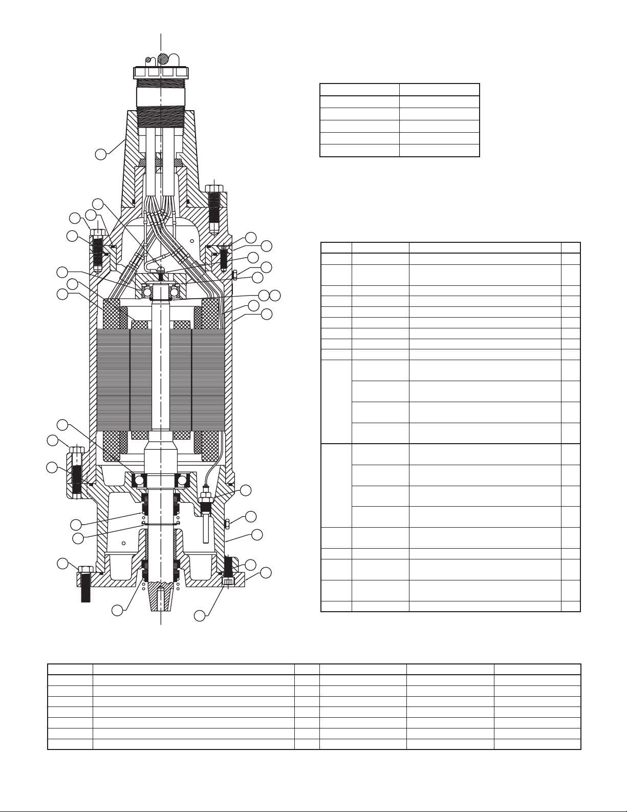
Disassembly
With the pump located in a secure place, remove the
bolts fastening the seal housing to the volute. The
motor and impeller can now be removed as a unit.
Lay the unit down on its side. If the lower seal is to be
removed, it is recommended that the oil in the seal
chamber be drained. This can be done by removing
the lower seal chamber plug and draining the oil into a
holding container.
To remove the impeller: Using a proper wrench, the
impeller retaining bolt and washer must be removed.
This may require a piece of wood placed between the
vanes to keep the impeller from rotating while removing
the bolt. Once the bolt has been removed, tap lightly with
a hammer around the outside diameter of the impeller to
loosen from shaft and key. After removing impeller, the
seal retainer needs to be removed to expose seal.
Caution: The impeller is large and heavy and will need to
be supported.
If the lower seal needs removed, rst remove the
compression spring that rides between the impeller and
the seal assembly. Next, take a pair of screwdrivers and
remove the compression ring that surrounds the rubber
bellows on the rotating portion of the seal assembly.
Again using the screwdrivers, pry the remaining portion
of the rotating seal assembly off the shaft. The ceramic
stationary can be removed by placing a screwdriver
between the rubber and the ceramic face, and then
prying, working around the entire diameter. Note,
these parts should be discarded and a new seal
assembly installed.
If the oil in the seal chamber was drained, examine
the contents to determine if the upper seal has been
damaged. Signs of grit or other abrasive material may
indicate that the upper seal has also been damaged.
Pressurizing the motor housing assembly between 7 and
10 psi and observing any drop in pressure will indicate if
the upper seal is functioning properly.
Note: Upper seal repairs must be done at a Myers
authorized service center or at the Myers factory.
Any unauthorized eld repair voids warranty and the
hazardous location approval on the Factory Mutual listed
pump.
The wear ring can be removed from the volute for repair
or replacement. First remove the retaining screws from
the wear ring. With a soft mallet the wear ring can be
tapped out of the volute case.
Reassembly
Remove the ceramic portion of the new seal from the
package. Brush new dielectric oil or glycerine around
the rubber portion of the stationary assembly and into
the pocket in the seal housing. Note, keep the oil off the
seal face. Without scratching the seal face, press the
ceramic stationary portion into the seal housing using a
Myers seal pusher. With clean cloth, lightly wipe the face
of the seal surface to make sure it is dirt free. Remove
the rotating portion of the seal from the package and
lubricate the inside diameter of the rubber bellows
and the outside diameter of the shaft. Place the seal
over the shaft (make sure the key is removed). Evenly
press on the body of the rotational assembly and slide
it down the shaft until the seal faces meet. Once the
seal assembly is in position, place the spring over the
register on the rotational portion of the seal.
Before placing impeller on shaft, the seal spring retainer
should be placed on shaft with stepped end toward seal
spring. Position the key into the seat in the shaft. Align
the impeller onto the shaft, making sure that the seal
spring is registered properly onto the back side of the
impeller. Insert the bolt and washer assembly into the
shaft and tighten to 43 ft.-lbs.