EDT directION FE257 User manual
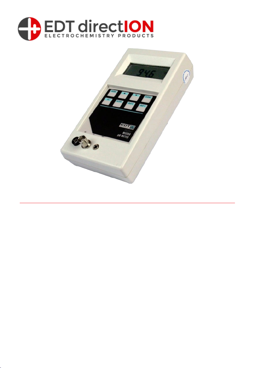
Table of Contents
Section 1 - Introduction and Set Up
Section 2 - pH Calibration & Measurement
Section 3 - mV Calibration & Measurement
Section 4 - Use of the Recorder Output
Section 5 - Troubleshooting
Appendix 1 - pH Electrodes & Buffers
Section 6 - Specification
FE257 - Advanced portable pH meter - Users Manual

SECTION 1 - Introduction
Description
The FE257 pH meter is a simple-to-use, portable, battery operated instrument.
Features include pH measurement with manual or automatic temperature
compensation, automatic calibration with standard buffers, and. with a resolution
of 0.1mV, can be used with ion selective electrodes.
Unpacking
Verify that you have received all equipment. If you have any questions about the
shipment, please call EDT Direct ION Ltd. or your agent.
When you receive the shipment, inspect the container for any signs of damage.
Note any evidence of rough handling in transit. Immediately report any damage to
the agent.
Note
The carrier will not honour any claims unless all shipping material is saved for
their examination. After examining and removing contents, save packing material
in the event that re-shipment be necessary.
The following items are packed in the box:
FE257 pH Meter E8051 Temperature Probe E8080 pH Electrode
pH Buffers 4,7 Carry Case 9V Battery
Operator Manual
Setting Up - Battery Installation
Approximately 35 hours of continuous use is afforded by the 9V battery.
The BAT flag appears on the display to indicate a low battery.
To install or replace the battery, slide off the back cover
Remove the old battery and insert a new one ensuring that the polarity is correct
Replace back cover.
Figure 1. Rear view of FE257
Note: Calibration is retained in all modes even when instrument is switched off and/or battery
removed.

Instrument Test Procedure
1. Switch on by pressing the I/O key. (Temperature probe should be disconnected.
2. Press the Mode key to select pH mode
3. Connect the BNC shorting plug to the pH input. The displayed reading should
read 7.00 ±0.02pH
4. Select mV mode by pressing the Mode key. Display should read 0.0 ±0.2mV
5. Select °C by pressing the Mode key. Ensure that the display has a value in the
range 0.0 to 19.0°C and is adjustable. i.e. responds to the use of the òñ keys.
Adjust to 20.0°C
6. The meter is ready for calibration
A Note on Electrodes
pH, Ion Selective and Redox electrodes may all be used with the FE257.
These may be combination or half-cell types. Combination or sensing half-cells
should have a BNC terminal and be connected to the socket marked pH/ION
input at the back of the meter.
Reference half-cells should have a 4mm bunched terminal and be connected to
the socket marked REF. Always refer to electrode instructions before use. See
also, Appendix 1.

Section 2 - Calibration and Measurement
For accurate results, stir all buffers and samples. Always rinse electrodes and blot dry
before transferring from one solution to another to prevent contamination. Ensure that
any electrode filling holes are left uncovered during use.
Automatic Calibration & Temperature Compensation
1. Connect the pH electrode(s) and temperature probe and switch on using the I/O Key.
2. Select pH mode and clear any calibration data by pressing the Clear key for 5 seconds.
3. Place the pH electrode(s) and the temperature probe in the pH 7 buffer and wait for a
stable reading. Press the BUF 1 key. The first calibration point will now be entered
automatically at the correct value for the temperature of measurement. The Cal flag will
be displayed.
4. Rinse, blot and place the pH electrode(s) and temperature probe in the second buffer
(4 or 10). Wait for a stable reading and press BUF 2. The second calibration point will
now be entered automatically at the correct value for the temperature of measurement.
5. Rinse, blot and place pH electrode(s) and temperature probe in the sample. Wait for a
stable reading and record pH value.
6. Temperature or mV measurements may be made at any time by pressing the mode
key.
7. To adjust the E° value of the electrode, place in buffer 4,7 or 10 and press the BUF 1
key.
Note: The performance of the electrode may be monitored by pressing the SLOPE key.
The slope is displayed as a % of Nernstian. The value should lie between 85 and 110%.
Manual Calibration
If buffers other than 4,7 and 10pH are to be used, then the calibration must be performed
manually. That is the correct pH values must be entered using the ñò keys
Follow points 1 and 2 for Auto calibration above :
3. Place the electrode(s) and temperature probe in the first buffer and wait for a stable
reading. Check the temperature of the buffer. Look up the value of the buffer for this
temperature
4. Use the keys to adjust the displayed reading to the value displayed in 3. (the CAL flag
will flash). Press BUF 1 (the CAL flag will stop flashing)
5. Place the electrode(s) and temperature probe in the second buffer and wait for a stable
reading. Check the temperature of the buffer. Look up the value of the buffer for this
temperature
6. Use the keys to adjust the displayed reading to the value displayed in 5. (the CAL flag
will flash). Press BUF 2 (the CAL flag will stop flashing)
7. Rinse, blot and place pH electrode(s) and temperature probe in the sample. Wait for a
stable reading and record pH value.
8. Temperature or mV measurements may be made at any time by pressing the mode key.
9. To adjust the E° value of the electrode, place in buffer 4,7 or 10 and press the BUF 1 key.

Manual Temperature Compensation
If the use of a temperature probe is inappropriate, e.g. small sample size then manual
temperature compensation can be used.
1. Disconnect temperature probe
2. Press the Mode key to select °C function. Note that the °C flag will flash when no
temperature probe is connected.
3. Use the òñ keys to adjust the displayed reading to the temperature of the first buffer.
4. Press the Mode key to return to pH function.
5. The meter may now be calibrated automatically or manually following either of the
procedures above.
Refer to the recorder instructions
1. Connect the recorder via the red and black 4mm sockets on the back panel. (Red
positive, Black negative)
2. Ensure that the recorder is set for the appropriate range, i.e.
Section 3 - mV Calibration and Measurement
The mV mode has two ranges. The meter will automatically select the most appropriate
range as follows:
0 to ±400mV with resolution 0.1mV
±400mV to ±2000mV with resolution 1mV
Absolute mV
1. Connect the electrode(s)
2. Press the Mode key to select mV function
3. Clear any existing data. (Press Clear for 5 seconds)
4. Absolute mV readings may now be made by immersing the electrodes in the
sample and recording the reading.
Relative mV
Follow e procedure for Absolute mV from 1. to 3.
4. Immerse electrode(s) in the standard or blank solution. Wait for a stable
reading and press BUF 1. The display will automatically zero and the CAL flag will
be displayed.
5. mV values relative to the standard solution may now be taken by immersing in
the sample and recording the reading.
Section 4 - Use of the Recorder Output
Mode Range Display Recorder
pH 0-200 7.00pH 70.0mV
mV ±200 500mV 50.0mV
°C ±200 25.0°C 25.0mV

Error Codes
PRO Temperature probe malfunction
Buf Wrong or Contaminated Buffer (pH Mode only)
SL Poor Electrode Slope caused by faulty electrode or poor buffers/
standards
E° Faulty or Aged electrode
E6, E7 Calibration error. Recalibrate with fresh standards or buffers Electrodes
out of solution.
In the event of a malfunction, it is important to pinpoint the problem to either the meter or the cell. If
a spare cell is available, substitute it for the one in use.
There are no user serviceable parts in this instrument. Please ensure that the instrument, together
with all accessories, is returned to EDT Direct ION Ltd or the agent with a full description of the
symptoms. No attempt should be made to repair the meter.
Symptom
No display
‘BAT’ flag displayed
Wildly erratic readings or Display shows -- in
left hand digit (Over-range condition)
Drifting readings
Erratic/drifting readings or display reads – on
left hand side when shorting plug is attached.
Section 5 - Troubleshooting
Probable Cause
Battery is flat or not installed
Power supply Disconnected
Battery Low
Electrodes disconnected
Electrodes not immersed in solution
Reference electrode not filled
Reference junction dry
Inconsistent or lack of stirring Reference
filling solution contaminated
Buffers contaminated
Return meter for servicing
Section 5 - Specifications
pH Range/Resolution 0.00 to 14.00
pH Accuracy ±0.02pH
Temperature Compensation 0-100°C
Auto Calibration 2 points, 4,7 or 10
Manual Calibration 2 points at any value
mV Range/Resolution ±400.0 & ±2000 mV
mV Accuracy ±2% ±1 digit
Relative mV offset ±2000mV
Auto Range change at 400mV
°C Range/Resolution -30.0 to +130.0°C
°C Accuracy ±0.3°C
Recorder Output ±200mV
Slope Units % Nernstian
Display 12.7mm LCD
Power 9V Battery or AC
Instrument Size 100 x 180 x 44mm
Instrument Weight 410g

Appendix 1 - pH electrodes
Before Use
Remove the protective cap covering the glass sensing bulb and replace with the protective guard if
applicable. Inspect the filling solution for air bubbles and remove by shaking in a downward direction.
Soak the electrode in pH storage solution for 30 minutes.
Cleaning
Soak the electrode in 0.1M HCl for 15 minutes followed by soaking in pH storage solution for 30
minutes
Storage.
Put some pH storage solution in the protective cap and place over the glass bulb.
Never store the electrode in distilled or de-ionised water. Never allow the electrode to dry out.
pH electrode storage solution is made up by dissolving 1g KCl in 100mL of pH 7 buffer
Buffer Capsules
Buffer capsules are made up as follows For each buffer, empty the powder into a suitable container.
Using deionised water, make up to 100mL ensuring that the powder is filly dissolved before use. The
coloured outer skin may be added to colour code the resulting buffer. This may take up to 4 hours to
dissolve but will not affect the pH of the buffer.
Buffer Solutions
If using ready made solutions, use ones supplied with temperature coefficient information
Table of Temperature Coefficients For EDT Buffers
pH Buffers
°C pH 4 pH 7 pH 10
10 3.99 7.07 10.18
15 4.00 7.04 10.14
20 4.00 7.02 10.06
30 4.00 6.99 9.95
35 4.01 6.98 9.91
40 4.02 6.97 9.85
50 4.05 6.96 9.78
60 4.07 6.96 9.75
25 4.00 7.00 10.00

For more information on our products
please visit our website www.edt.co.uk
EDT directION
Unit 5 Waldershare Park, Dover. CT15 5DQ.
Telephone: 01304 829960 Email: [email protected]
Company No, 04135318 VAT No. GB 765175410
Table of contents
Other EDT directION Measuring Instrument manuals

EDT directION
EDT directION QP451 Instruction manual

EDT directION
EDT directION RE388TX User manual

EDT directION
EDT directION QC355TX User manual

EDT directION
EDT directION DR359TX User manual

EDT directION
EDT directION QP481 Instruction manual

EDT directION
EDT directION QP458 User manual

EDT directION
EDT directION QP999 4 Series User manual
Popular Measuring Instrument manuals by other brands


PCB Piezotronics
PCB Piezotronics 352C68 Installation and operating manual

Sinpo
Sinpo DRO II Series Operation manual

RIEKER
RIEKER Flex H6EX-A2 installation manual

Keysight Technologies
Keysight Technologies N6705C Operating and service guide

HBM
HBM KDB operating manual

SUTO
SUTO S461 Instruction and operation manual