EDT directION DR359TX User manual
Table of Contents
Section 1 - Introduction and Set Up
Section 2 - pH Calibration & Measurement
Section 3 - Ion Calibration & Measurement
Section 4 - mV Calibration & Measurement
Section 5 - Use of the Recorder Output
Section 6 - Use with a Printer or Computer
Section 7 - Troubleshooting
Section 8 - Specification
Appendix 1 - pH Electrodes & Buffers
Appendix 1 - Concentration Units
Accessories - Accessories
DR359TX - Ion Meter - Users Manual

SECTION 1 - Introduction
Description
The DR359Tx Ion Concentration/pH meter can be used with pH, Ion selective and
redox electrodes. The meter will automatically calculate the relationship between
up to 5 ion standards allowing sample concentration to be read directly, avoiding
the plotting of calibration graphs.
Unpacking
Verify that you have received all equipment. If you have any questions about the
shipment, please call EDT Direct ION Ltd. or your agent.
When you receive the shipment, inspect the container for any signs of damage.
Note any evidence of rough handling in transit. Immediately report any damage to
the agent.
Note
The carrier will not honour any claims unless all shipping material is saved for
their examination. After examining and removing contents, save packing material
in the event that re-shipment be necessary.
The following items are packed in the box:
DR359Tx Ion Meter E8060 Electrode Stand AC Adapter 9V Battery
Operator’s Manual
Setting Up - AC Operation
Only use the approved power adaptor supplied
Check that the adaptor is the correct voltage for your power supply
Plug the adaptor into the power socket at the back of the meter, then connect to
the AC supply.
Battery Installation
Approximately 24 hours of continuous use is afforded by the 9V battery.
The BAT flag appears on the display to indicate a low battery.
To install or replace the battery, slide off the back cover
Remove the old battery and insert a new one ensuring that the polarity is correct
Replace back cover.
Figure 1. Bottom view of instrument
showing power connections

Instrument Test Procedure
1. Ensure that the shorting plug is connected to the BNC pH in-put at the back of
the meter. Switch on using the switch on the back panel.
2. Press the Mode key to select pH mode and clear any calibration data by
pressing the Clear key for 5 seconds.
3. The displayed reading should read 7.00 ±0.02pH
4. Switch to mV mode by pressing the mode key. Display should read 0.0 ±0.2mV
5. Switch to °C key by pressing the mode key. Ensure that the display has a value
in the range 0.0 to 19.0°C and is adjustable.
i.e. responds to the use of the keys. Adjust to 20.0°C
6. Switch to concentration mode (CONC) and ensure that the
display reads 10.0 ± 0.2
7. The meter is ready for calibration
A Note on Electrodes
pH, Ion Selective and Redox electrodes may all be used with the DR359Tx. These
may be combination or half-cell types. Combination or sensing half-cells should
have a BNC terminal and be connected to the socket marked pH/ION input at the
back of the meter. Reference half-cells should have a 4mm bunched terminal
and be connected to the socket marked REF. Always refer to electrode
instructions before use. See also, Appendix 1.
Figure 2. Rear view of DR359Tx
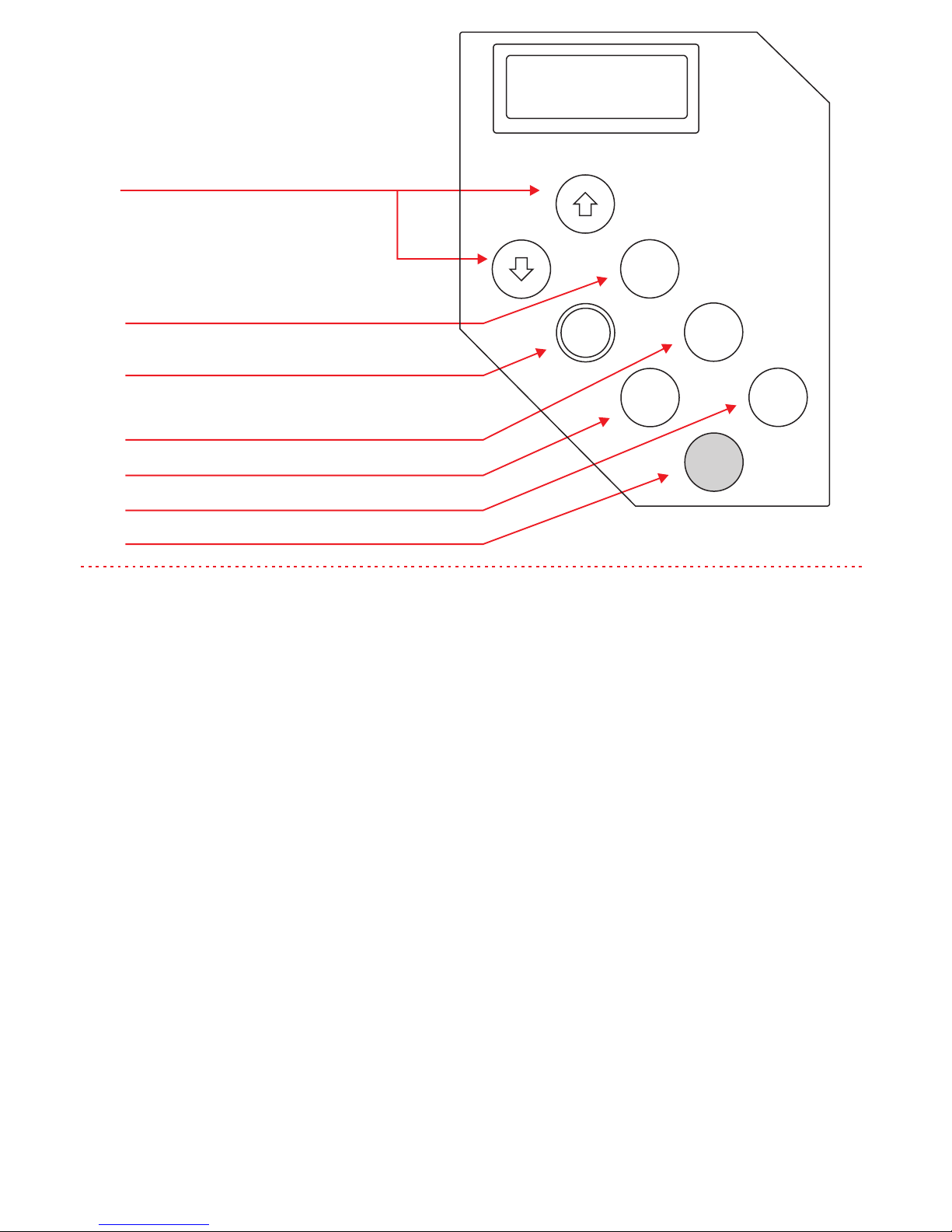
Calibration Keys - Alter displayed reading
Enters displayed value as calibration data
Displays electrode slope.
Transmits data to printer. Acts as Hold facility.
Selects measurement type—pH; mV; °C, Conc
Clears Calibration data when pressed for 5 s
Alters displayed decade.
Calibration key for Ion Concentration.
Figure 3. Front Panel
Section 2 - pH Calibration and Measurement
For accurate results, stir all buffers and samples. Always rinse electrodes and blot dry
before transferring from one solution to another to prevent contamination. Ensure that any
electrode filling holes are left uncovered during use.
Automatic Calibration & Temperature Compensation
1. Connect the pH electrode(s) and temperature probe and switch on using the power
ON/OFF switch on the back panel.
2. In order to calibrate in pH mode, any existing ion calibration data MUST be cleared.
Presence of calibration data is indicated by the CAL flag in the left hand corner of the
display. Select Conc mode and then press Clear for 5 seconds. Select pH mode.
3. Place the pH electrode(s) and the temperature probe in the first buffer and wait for a
stable reading. Press the Enter key. The fist calibration point will now be entered
automatically at the correct value for the temperature of measurement. The Cal flag will be
displayed.
4. Rinse, blot and place the pH electrode(s) and temperature probe in the second buffer.
Wait for a stable reading. Press the Enter key. The second calibration point will now be
entered automatically at the correct value for the temperature of measurement.
5. Rinse, blot and place pH electrode(s) and temperature probe in the sample. Wait for a
stable reading and record pH value.
Note: The performance/condition of the electrode(s) may be monitored by pressing the
Slope key. This displays the slope of the electrode as a % of the Nernstian or Theoretical
Slope. The value should lie between 80 and 110%.
Clear
Enter X10
Slope Mode
Send

Manual Calibration
If buffers other than 4,7 and 10pH are to be used, then the calibration must be performed
manually. That is the correct pH values must be entered using the ñò keys
Follow the procedure for Auto calibration above but before pressing the enter key (points 3
and 4) carry out the following procedure:
1. Check the temperature of the buffer
2. Look up the value of the buffer for this temperature
3. Use the ñò keys to adjust the displayed reading to the value displayed in (the CAL flag
will flash). Press Enter (the CAL flag will stop flashing)
Manual Temperature Compensation
If the use of a temperature probe is inappropriate, e.g. small sample size then manual
temperature compensation can be used. With the temperature probe disconnected, follow
the procedure for Automatic Temperature compensation on page ?. points 1 to 3.
4. Press the Mode key to select °C function. Note that the °C flag will flash when no
temperature probe is connected. Use the òñ keys to adjust the displayed reading to the
temperature of the first buffer.
5. Press the Mode key to return to pH function.
6. The meter may now be calibrated automatically or manually following either of the
procedures above.
Ion Concentration General tips for accurate results
Temperature
Always ensure that standards and samples are kept at the same temperature and remain
constant
Stirring
It is preferable to stir standards and samples. Stir such that no vortex is visible
If using a magnetic stirrer, it is advisable to put a piece of insulating material between the
plate and the vessel to eliminate any temperature effects arising from the stirrer itself.
Some samples are impossible to stir consistently. If this is the case, it may be better not to
stir but be sure to treat all standards in the same way. Alternatively consider using an
incremental method of analysis such as Known addition or subtraction.
Avoiding Contamination
Always rinse the electrodes and blot dry before transferring from one solution to another
Move from the most to the least dilute standard
Ionic Strength Adjustment
A solution of high ionic strength is added to all standards and samples. This minimises
differences in background ionic strength between solution and enables conductivity (as
opposed to activity) to be measured directly.
Section 3 -

Calibration and Measurement
Note: Refer to Appendix 2 on concentration units before proceeding
1. Up to 5 calibration points may be entered. Standards should be prepared such that
their concentrations lie either side of the expected sample range. If 2 standards are to be
used then ideally they should be 10fold apart in concentration. E.g. for an expected
sample concentration of 5ppm, standards of 1 and 10ppm should be prepared.
2. Connect the Ion selective electrode to the BNC input at the back of the meter. If using a
separate reference electrode, connect to the 4mm input. Switch on using the black
ON/OFF
3. In order to work in Concentration mode, any existing pH calibration data MUST be
cleared. Select pH mode. If the CAL flag is displayed, press the Clear key until it
disappears.
4. Press the mode key until Conc is displayed.
5. Place electrodes in the first standard and wait for a stable reading (the value displayed
is an arbitrary number at this stage).
6. Press the x 10 key (if necessary) to adjust the value to the correct decade, then use the
ñò keys to adjust to the exact value of the standard. (The CAL flag will flash during this
procedure.). Press Enter. (The CAL flag will stop flashing).
7. Place electrodes in the next standard and repeat and
8. If further standards are to be used repeat from for each standard.
9. Ion concentration measurements may now be made by immersing the electrodes in the
prepared sample and recording the displayed reading.
Note: The performance of the electrodes can be assessed by pressing the Slope key. This
will display the mV/decade slope which can then be compared with the theoretical value
Section 4 - mV Calibration and Measurement
The mV mode has two ranges. The meter will automatically select the most appropriate
range as follows:
0 to ±400mV with resolution 0.1mV
±400mV to ±2000mV with resolution 1mV
Absolute mV
1. Connect the electrodes
2. Press the Mode key to select mV function
3. Clear any existing data. (Press Clear for 5 seconds)
4. Absolute mV readings may now be made by immersing the electrodes in the sample
and recording the reading.

Relative mV
Follow the procedure for Absolute mV from 1 to 3
4. Immerse electrode(s) in the standard or blank solution. Wait for a stable reading and
press Enter. The display will automatically zero and the CAL flag will be displayed.
5. mV values relative to the standard solution may now be taken by immersing in the
sample and recording the reading.
3. To print out a sample reading, press the Send key. The first
time the key is pressed the following printout is obtained
4. Pressing and releasing the Send key subsequently will
result in a printout of the displayed reading and temperature
only.
5. To obtain a printout of other parameters for the same
sample, press the Mode key and then the Send key
6. To print a new identifier, press and hold down the Send
key.
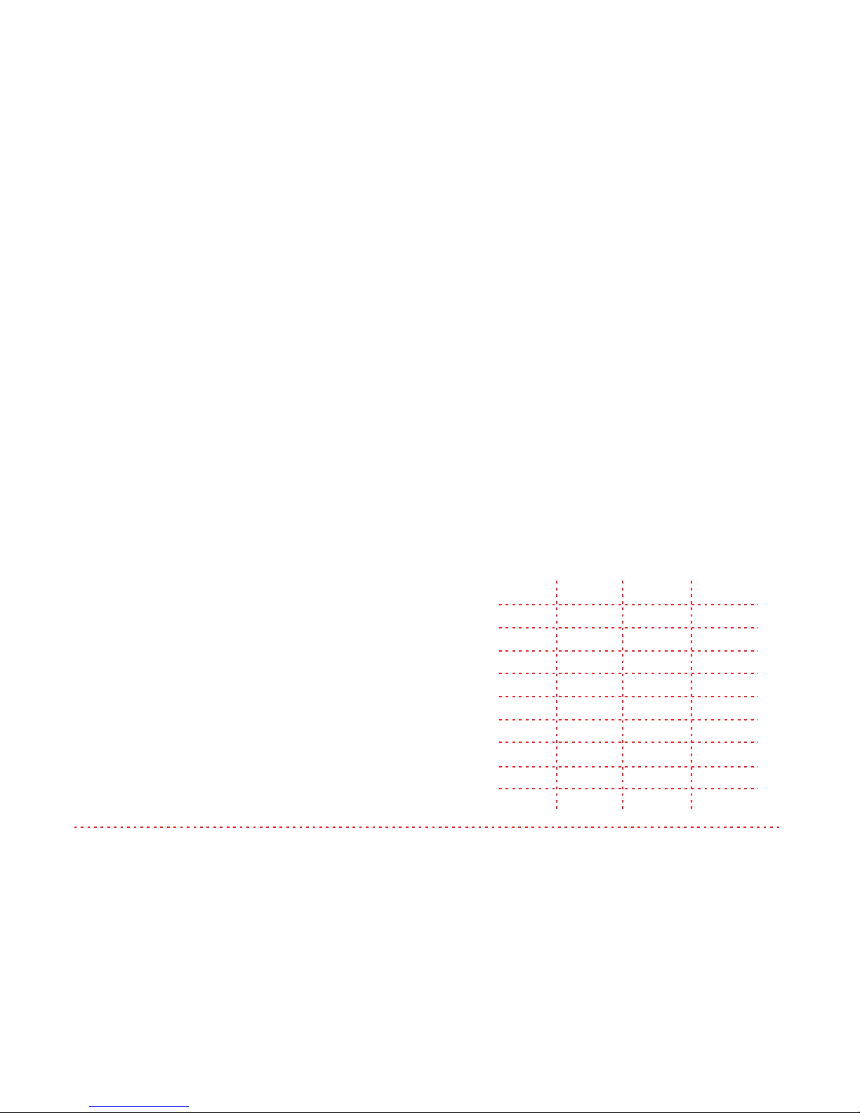
Section 5 - Use of the recorder output
Connect the recorder via the red and black
4mm sockets on the back panel.
(Red positive, Black negative)
Ensure that the recorder is set for the
appropriate range, as shown.
Mode
Ion
pH
mV
°C
Range
0-200
0-200
±200
±200
Display
---------
7.00pH
500mV
25.0°C
Recorder
mV/10
70.0mV
50.0mV
25.0mV
DATE………………….
OPERATOR…………...
SAMPLE………………
pH = 7.00pH T=21.7°C
Section 6 - Operation With a Printer or Computer
Printer
1. Connect a printer (set at 1200 Baud) to the meter via the RS232C port on the back panel.
2. Follow the calibration procedure given in Section 2 or 3
Computer
Connect a computer using 1200 Baud via the RS232C port at the back of the meter. A
computer program is required to receive and send characters from the computer. The
current readings can be sent to the computer by pressing the Send key. Each line is
terminated with a Carriage Return (CR), Line Feed (LF). All characters are ASCII printable
alpha-numeric
Three commands, CA, PR and RD can be sent from the computer:

Command—CA
1 CR LF
pH = 7.06 CR LF
T = 15.8 °C CR LF
mV = -0.2mV CR LF
2 CR LF
Second calibration point
Command—RD
pH = 7.00pH CR LF
T = 21.5°C CR LF
mV = 0.2mV CR LF
CA—Send Calibration Data
RD –Send Current Readings
Command—PR
Sl = 95.3% NERNST CRLF
E° = 5.2mV CR LF
PR –Send Probe Status Data
RS232 Connection details
Rx
Tx
CTS
GND
Section 7 - Troubleshooting
Symptom
Probable Cause
No display
Battery is flat or not installed
Power supply disconnected
‘BAT’ flag displayed
Battery Low
Wildly erratic readings or display reads --
on left hand side
Electrodes disconnected
Electrodes not immersed in solution
Reference electrode not filled
Reference junction dry
Drifting readings
Inconsistent or lack of stirring
Reference filling solution contaminated
Buffers contaminated
Erratic/drifting readings or display reads –
on left hand side when shorting plug is
attached.
Return meter for servicing

Error Codes
PRO - Temperature probe malfunction
Buf - Wrong or Contaminated Buffer (pH Mode only)
SL - Poor Electrode Slope caused by faulty electrode or poor buffers/ standards
E° – Faulty or Aged electrode
E6, E7 - Calibration error. Recalibrate with fresh standards or buffers Electrodes out
of solution.
In the event of a malfunction, it is important to pinpoint the problem to either the
meter or the cell. If a spare cell is available, substitute it for the one in use.
There are no user serviceable parts in this instrument. Please ensure that the
instrument, together with all accessories, is returned to EDT Direct ION Ltd or the
agent with a full description of the symptoms.
No attempt should be made to repair the meter.
Concentration Display Range 0.001 to 9990units
Resolution 3 significant figures
Accuracy ±0.5%
Slope Units mV/Decade
pH Range/Resolution 0.00 to 15.00
pH Accuracy ±0.02pH
Slope Units % Nernstian
Temperature Compensation 0-100°C
Auto Calibration 2 points, 4,7 or 10
Manual Calibration 2 points at any value
mV Range/Resolution ±400.0 & ±2000 mV
mV Accuracy ±2% ±1 digit
Relative mV offset ±2000mV
Auto Range change at 400mV
°C Range/Resolution -30.0 to +130.0°C
°C Accuracy ±0.3°C
Recorder Output ±200mV
Karl Fischer Output 10µA
Display 12.7mm LCD
Power 9V Battery or AC
Instrument Size 210 x 150 x 88mm
Instrument Weight 550g
Section 8 - Specifications
Appendix 1 - pH electrodes
Before Use
Remove the protective cap covering the glass sensing bulb and replace with the
protective guard if applicable. Inspect the filling solution for air bubbles and remove
by shaking in a downward direction. Soak the electrode in pH storage solution for 30
minutes.
Cleaning
Soak the electrode in 0.1M HCl for 15 minutes followed by soaking in pH storage
solution for 30 minutes
Storage.
Put some pH storage solution in the protective cap and place over the glass bulb.
Never store the electrode in distilled or de-ionised water. Never allow the electrode to
dry out.
pH electrode storage solution is made up by dissolving 1g KCl in 100mL of pH 7 buffer
pH Buffers - Buffer Capsules
Buffer capsules are made up as follows For each buffer, empty the powder into a
suitable container. Using deionised water, make up to 100mL ensuring that the
powder is filly dissolved before use. The coloured outer skin may be added to colour
code the resulting buffer. This may take up to 4 hours to dissolve but will not affect
the pH of the buffer.
Buffer Solutions
If using ready made solutions, use ones supplied
with temperature coefficient information.
Please See Table of Temperature Coefficients
For EDT Buffers Adjacent
°C pH 4 pH 7 pH pH10
10 3.99 7.07 10.18
15 4.00 7.04 10.14
20 4.00 7.02 10.06
25 4.00 7.00 10.00
30 4.00 6.99 9.95
35 4.01 6.98 9.91
40 4.02 6.97 9.85
50 4.05 6.96 9.78
60 4.07 6.96 9.75
Appendix 2 - Concentration Units
The DR359Tx can measure concentration in the range 0.001 to 9990 units. If this
range is insufficient, then a multiplier must be applied to all readings e.g.
Ÿ Calibration Standard A = 10-6 M
Ÿ User keys in value of 0.001 and records a multiplier of 10-3
Ÿ Calibration standard B = 10-5 M
Ÿ User keys in value of 0.01
Ÿ Sample reads 0.007, say, then the actual sample concentration should be recorded
as 0.007 x 10⁻³M i.e. 7 x 10⁻⁶ M

Accessories - Ion Selective Electrodes (Combinations)
Species Code
Ammonia 3302
Ammonium 3051
Barium 3081
Bromide 3271
Cadmium 3241
Calcium 3041
Carbonate 3091
Chloride 3261
Cupric 3227
Cyanide 3291
Fluoride 3221
Iodide 3281
Accessories - pH Electrodes (Combinations)
Description Code
Glass Body General Purpose E8081
Plastic Body General Purpose E8080
Spear Tip (6mm) E8083
Penetration E8084
Low Conductivity E8085
Long Reach E8086
Flat Surface E8087
Tris Buffers E8099
Semi Micro E8100
Semi Micro for Tris E8101
Other Accessories
Description Code
Temperature Probe E8051
Electrode Stand E8060
AC Adaptor E8040 (FE)
E8041 (UK)
E8042 (US)
E8043 (EU)
Please contact EDT Direct ION or your agent for further information on accessories
available or visit www.edt.co.uk
Species Code
Lead 3231
Mercury 3251
Nitrate 3021
Nitrite 3071
Perchlorate 3061
Potassium 3031
Silver 3211
Sodium 3301
Sulphide 3225
Thiocyanate 3229
Water Hardness 3100

For more information on our products
please visit our website www.edt.co.uk
EDT directION
Unit 5 Waldershare Park, Dover. CT15 5DQ.
Telephone: 01304 829960 Email: [email protected]
Company No, 04135318 VAT No. GB 765175410
Other EDT directION Measuring Instrument manuals

EDT directION
EDT directION QP481 Instruction manual

EDT directION
EDT directION FE257 User manual

EDT directION
EDT directION QP451 Instruction manual

EDT directION
EDT directION QP458 User manual

EDT directION
EDT directION RE388TX User manual

EDT directION
EDT directION QC355TX User manual

EDT directION
EDT directION QP999 4 Series User manual
Popular Measuring Instrument manuals by other brands


ITS Telecom
ITS Telecom DD890 manual

Flow vision
Flow vision FC50-EX Instructions for installation and adjustment

Bosch
Bosch GLM 30 Professional Original instructions

METREL
METREL power master MI 2892 instruction manual

EINHELL
EINHELL 21010 Original operating instructions

Electrex
Electrex x3m-D installation manual


