EDT directION QP458 User manual

QP458 Portable pH and
Conductivity/TDS Meter – Manual

-Power (On/Off)
-Contrast/Backlight
-Mode
-Calibrate
-Logging and Printing
-Read/Accept
-Navigate the Menu
-Set up Menu
QP458 Portable pH/mV/Conductivity/TDS Meter - Quick User Guide
Thank you for choosing the QP458 Portable pH meter from EDT directION. This guide will enable you to quickly set up and use
the instrument. The QP458 has the same functionality and specification as the QP451 pH meter and QP481 Conductivity meter
combined. It does however have the capability to measure and display pH and Conductivity simultaneously.
Description
Series 4 instruments have a dynamic LCD display which guides the user through the calibration and measurement process. We
hope there will be no need to refer to a manual once you have performed initial set up.
Unpacking
Verify you have received all the equipment ordered. If you have any questions, please contact EDT directION Ltd or your agent.
Check the package for any signs of damage. If there are any signs of rough handling in transit, please report it to the agent
immediately. Provide photographic evidence if possible. Damage should be reported within 7 days of receipt.
Note: The carrier will not honour any claims unless all shipping material is saved for their examination. Once removed save all
packing material if re-shipment is required.
Packing List:
If you ordered the QP458 Meter only option, the package will only contain the QP458 Portable Meter and 4 X AA Batteries. If
you ordered the QP458 Portable pH/mV/Conductivity/TDS Meter Kit the following items are packed in the case:
Tough carry case, QP458 Meter, 4 x AA Batteries, E8080 pH combination Electrode, ATC/Temp probe, Combined Conductivity
/Temp cell, pH 4 and 7 Buffer Solutions,1413uS Standard solution user Guide, USB data stick, Mini USB data cable.
Setting up
Battery installation.
Remove the battery cover by loosening the retaining cross head screw. Please note this screw has a retainer and will therefore
remain with the cover to prevent loss.
Once open unpack the 4 AA Batteries supplied and insert ensuring the polarity is correct for each battery. Replace the cover.
Setting the Time and Date.
1. Switch the unit on using the on/off button.

2. Press the right arrow key to enter the PARAMETERS ADJUST SCREEN
3. Scroll down to the DATE FORMAT option and press READ until you arrive at the desired format.
4. Scroll down to the CLOCK option using the down arrow key.
5. Press READ to enter the CLOCK screen.
6. Select CANCEL using the down arrow key and press READ until the current DATE in the entry box is removed.
7. Select the current date digit by digit by selecting the correct number and pressing READ.
8. When the entry box contains the correct date select ENTER and press READ.
9. You are now in the TIME screen. Repeat from 5 above to select the correct time.
10. From the PARAMETERS ADJUST screen press READ to return to the combined pH and Conductivity Mode.

(For 1-point Calibration)
Calibration and Measurement
pH Calibration
Accurate pH measurement requires that you do not cross contaminate buffers and samples. Before using the pH probe ensure it
is rinsed with deionised water and blotted dry. Repeat this procedure when transferring between all standards and samples.
1. Connect the pH Electrode to the BNC connector on the top rear of the instrument.
2. Connect the ATC probe Jack into the 3.5 mm Jack socket next to the BNC socket.
3. Press the on/off switch. The display will light up.
4. The meter is now in Combined pH and Conductivity Mode. Press MODE until you are in pH Mode.
5. The meter is now in the pH mode. Press CAL to start calibration.
6. Insert the pH Probe and ATC electrode into the pH7 Buffer solution and press READ.
7. The auto endpoint indicator will show the progress of the calibration. When stable the meter will set itself to pH
7.00 (or the corrected value)
8. To use this 1-point calibration press CAL. We recommend a 2-point calibration to do this rinse the pH Electrode and
ATC electrode with DI water, blot dry and immerse into the pH 4 Buffer solution.
9. Press READ to start the second point Calibration.

10. The auto endpoint indicator will show the progress of the calibration. When stable the meter will set itself to pH
4.00 (or the corrected value)
11. To accept the Calibration, check the Slope is over 80% and Press CAL.
12. Remove the pH Probe and ATC from the solution. Rinse with deionised water and blot dry
13. Insert the pH Probe and ATC Electrode into the sample solution and press READ
14. The auto end point will freeze the display when the reading is stable
15. For further samples repeat from 11 above
Using different or Custom Buffer solutions:
The QP458 comes complete with pH 7 and pH 4 Buffer solutions. These Buffers are automatically set up in the menu as is pH 10
Buffer. The reference temperature for these buffers is 25 Degrees C. For 20 degree C Buffers or custom values you will need to
enter the Set Up menu:
1. After switching the instrument on press MODE to get into pH Mode. Then press the right arrow set up key.
2. In the PARAMETERS ADJUST screen scroll down to “Buffer Set” and press READ
3. In the “SELECT BUFFER SET” screen select option 2 and press READ to select a pH 4,7 &10 at 20 degrees.

4. Or Select Option 3 to input custom Buffer values and Press READ
5. In the USER BUFFER SET screen select the option 1 and press right arrow
6. Press the down arrow to select CANCEL. Press READ to remove the current value.
7. To select a custom buffer, highlight the value and press READ.
8. When you have the correct value in the ENTRY box select ENTER and press READ.
9. Repeat for Custom buffers 2 and 3. Note: You can still perform 1,2 or 3 point Calibrations. i.e. you don’t have to
use all 3 buffers.
10. Press READ to return to the PARAMETERS ADJUST screen and press READ again to revert to the pH Mode.
11. To calibrate follow the Calibration procedure above.
Conductivity Calibration
Accurate conductivity measurement requires that you do not cross contaminate standards and samples. Before using the
Conductivity probe ensure it is rinsed with deionised water and blotted dry. Repeat this procedure when transferring between al
standards and samples.
1. Connect the conductivity cell into the Din connector on the top rear of the instrument.
2. Press the on/off switch. The display will light up.

3. Press MODE until the meter is in the Conductivity mode. Press CAL to start calibration.
4. Insert the probe in the standard solution (swirl with the cell if required) and press READ
5. The auto endpoint indicator will show the progress of the calibration. When stable the meter will set itself to the
calibration value.
6. Remove the cell from the solution. Rinse with deionised water and blot dry.
7. To measure a sample, press READ and then insert the probe into the sample solution (swirl if required) and press READ
8. The auto end point will freeze the display when the reading is stable
9. For further samples repeat from 6 above
Using different Calibration Standard solutions:
The QP458 comes complete with a 1413uS/cm standard solution. This standard is automatically set up in the menu. To use a
12.88mS/cm standard do the following:
1. After switching the instrument on press MODE until you are in Conductivity Mode, then press the right arrow set up
key.
2. In the PARAMETERS ADJUST screen scroll down to “Cal Standard” and press READ

3. The instrument now selects the 12.88mS standard. Scroll back up to CONTINUE and press READ.
4. Calibrate as above but using a 12.88 mS/cm standard solution.
5. To select a different standard in the PARAMETERS ADJUST screen scroll down to “Cal Standard” and press READ (once
or twice depending on the previous setting) until the “Custom Standard” page appears. Then press the right arrow key.
Ensure the “Entry” box is empty (select “Cancel” to clear a full box) and input a Custom Standard in mS/cm.
6. Select “Enter” to finish. Then scroll up to Continue and press READ.
Using Conductivity Cells with different cell constants (K value)
The instrument default is set at K=1. The actual cell constant is calculated during calibration however some applications require
the input of a cell constant as the calibration. The most common cell constants for specialist applications are K=0.1 and K=10. To
set a cell constant:
1. After switching the instrument on press MODE until you are in Conductivity Mode, then press the right arrow set up
key.
2. In the PARAMETERS ADJUST screen scroll down to “Cell Constant (K)” and press READ. You are now in the “Cell
Constant” (K) screen
3. Ensure the “Entry” box is empty (select “Cancel” to clear a full box) and input a Custom cell constant e.g. 0.1.
4. Select “Enter” to finish. Then scroll up to Continue and press READ.

Logging and printing
The QP458 Portable Conductivity and pH meter has both a log and a print function. You can print and log directly to an external
device when connected via the Mini USB output or straight to file.
Storing data and Logging.
The Series 4 instruments have a substantial internal memory which can contain up to 64 sets of results/data.
Data can be stored in the internal memory in any mode after any reading has been taken. To ensure good data integrity it is
recommended that you set up the instrument with the correct data, time and user ID details. Please refer to section 1 of this
manual. This information will be stored along with the sample readings.
Saving Sample Readings.
Once you have measured a sample in any mode and the reading is frozen you will be offered the option to “Press LOG to print
immediate”. Press “LOG” to store the reading in the internal memory. The file will be stored with the name “AD-HOC x “where x
is a sequential number that increases by 1 each time a result is recorded.
Files are accessed by:
-Press right arrow after unfreezing the display. This takes you to the “PARAMETERS ADJUST” screen.
-Select “Logging and Print set up” and press READ
-Select “REVIEW Files” and press READ
-Select the desired file and press right arrow to reveal the data.

Logging Data
The Series 4 instruments allow the continuous logging of up to 10,000 data points for up to 99 hours at intervals as small as 1
second.
To log data, it is important to “Set Up” the logging parameters:
-Press right arrow from any Mode to access the set up page.
-This takes you to the “PARAMETERS ADJUST” screen.
-Select “Logging and Print set up” and press “READ”
-Select User ID and Press “READ”
-Select the user you want to modify and press right arrow.Once finished select Enter and press “READ”
-Press “READ” to select the user.
-Select “Set Time Interval” and press “READ”. Input time interval.
-Select “Time Period to Log” and press “READ”. Input Time period.
-Select “Filename” and press “READ”. Input File Name.
-Select “CONTINUE” and press “READ”

-Ensure the instrument is Calibrated in the mode you are about to LOG.
-Press “LOG” then Press “LOG” to start logging.
The instrument will start logging immediately. The Screen will display “LOGGING” then go into a low energy mode to preserve
battery life during the measurement.
To terminate the logging prematurely press “ON/OFF”. The display will show “Logging Aborted”.
When the Logging is finished press “READ” to finish.
To read the logged data:
-Press right arrow to enter SET UP page.
-Select “Logging and Print set up” and press “READ”
-Select “REVIEW Files” and press “READ”
-Select the desired file and press right arrow to reveal the data.
-To download the data to Excel use the EDT Data Wizard.

The EDT Data Wizard
The Series 4 Portable Meters have the facility to store Readings, Calibration data and Logged data in its internal memory filing
system.
To transfer this data directly into Excel for printing or further manipulation you will need to install the EDT data Wizard. This is
provided in the Series 4 Data Kit which comprises:
-USB flash drive with the EDT data Wizard Software.
Troubleshooting
The QP458 will automatically diagnose and indicate errors or issues on the display.
Most errors in pH measurement will be a s a result of a problem with the pH probe and not the meter. Please ensure your
Electrode is in good condition, has been cleaned and that before measurement it is rinsed in deionised water and blotted dry.
Ensure you have sufficient battery power. There is a battery life indicator in the top right of the display. If there are no solid
sections, the battery will need replacing. To save battery life reduce the screen brightness and contrast by selecting the
“Lightbulb” button.

Technical Specifications
QP458 Portable pH/mV/Conductivity/TDS Meter
pH Range
-2 to 16 pH Units
pH Accuracy
+/- 0.01 pH units
mV Range and Accuracy
+/- 1999.9 mv to +/= 0.1 mV
Conductivity Range
Autoranges up to 999mS/cm. Resolution (range dependent) down to 0.01uS/cm
Environment
Operates between 0-50 degrees and 0-100% RH
Relative mV mode
Sets any solution to 0mV.
Connection
BNC for Combined pH Electrode. 3.5 mm Jack for ATC probe
Data Output
Mini USB. Outputs csv at 38400 Baud
Data Storage
Dynamic Internal storage of up to 64 files. Logging maximum 10,000 data points
Display
Backlit LCD Graphic Display
Power requirement
4 X AA Batteries. Over 200 Hours continuous use. Power saving features include: Auto off,
Backlight control, logging sleep mode.
Reference Temperature
Set at 25 degrees C.
Size
175x88x48mm (lxwxh). Meter Only
Temperature Coefficient
Set at 2% Per degree.
Temperature Range
0 to +105 Degrees Centigrade
Weight
350g Meter Only
Contact Us
For Help and Technical Support take a look at our support pages on www.edt.co.uk or contact us:

DECLARATION OF CONFORMITY
We (EDT directION Limited) confirm that the following Series 4Portable electrochemistry
Meters have been tested, and have met, the requirements for compliance with CE and
UKCA directives listed below.
Model QP451, QP481,QP458 and SALCON II.
Supplied
by: Of: EDTdirectION Limited
Unit 5Waldershare Park Estate
Eythorne
Dover
Kent
CT15 5DQ
We declare that it complies with the Electromagnetic Compatibility Directive, 2014/30/
EU. We also declare that it complies with the Low Voltage Directive 2014/35/EU.
Compliance was demonstrated by conformance to the following specifications.
Testing performed by dB Technology Limited, Cambridge UK on behalf of Buckman
Hardy Associates, Electrochemical Engineers, Deal, Kent CT14 9RD
EMC:
LVD:
EN61326-2-2:2013 Electrical equipment for measurement, control and
laboratory use - EMC requirements. Part 2-2:Particular requirements for
portable test equipment used in low-voltage distribution systems.
EN61010-2-030: 2010 Safety requirements for electrical equipment for
measurement, control and laboratory use. Part 2-030: Particular
requirements for testing and measuring circuits
9th June 2021
Paul Stockton
Director

www.edt.co.uk
This manual suits for next models
1
Table of contents
Other EDT directION Measuring Instrument manuals
EDT directION
EDT directION RE388TX User manual
EDT directION
EDT directION FE257 User manual
EDT directION
EDT directION DR359TX User manual
EDT directION
EDT directION QP999 4 Series User manual
EDT directION
EDT directION QP451 Instruction manual

EDT directION
EDT directION QC355TX User manual
EDT directION
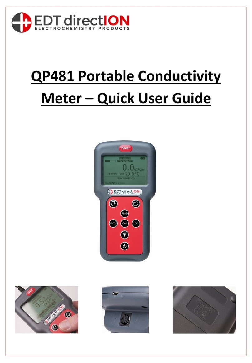
EDT directION QP481 Instruction manual


