Edwards Signaling SuperDuct TSD-CJ Service manual

Technical Bulletin
SuperDuct Four-Wire Duct Smoke Detector 1
SuperDuct
Four-Wire Duct Smoke Detector
P/N 3100685 • Rev 1.0 • 05MAY04
Combination duct smoke sensor and controller
Duct smoke sensor Duct smoke sensor
controller
Content
Introduction ............................................................................1
Related documents ..................................................................2
Duct smoke detector limitations ...............................................2
Product description ...............................................................2
Overview ..................................................................................2
Features ...................................................................................4
Specifications ...........................................................................4
Accessories..............................................................................5
Operation ................................................................................5
Controls and indicators.............................................................5
Normal state.............................................................................6
Alarm state ...............................................................................6
Trouble state ............................................................................6
Multiple duct detector operation ...............................................7
Duct detector installation ......................................................7
Installation guidelines ...............................................................7
Wiring guidelines......................................................................7
Installation sequence................................................................7
Changing sensor dirty test operation........................................7
Attaching a controller to a sensor in the field............................8
Sampling tubes ......................................................................8
Installing the sampling tube from the front of the detector........ 8
Support for 36-inch or longer sampling tubes .......................... 8
Wiring...................................................................................... 9
Separating power-limited and nonpower-limited wiring ............ 9
Terminal identification ..............................................................9
Wiring diagram ......................................................................... 9
Maintenance and service....................................................... 9
Recommended service schedule .............................................9
Sensor tests .............................................................................9
Controller tests ....................................................................... 10
Remote test/reset station tests............................................... 10
Troubleshooting ..................................................................... 11
Cleaning the duct smoke sensor ............................................ 11
Introduction
This document provides technical information for the
following SuperDuct™ duct smoke detector models:
Model number Description
TSD-CJ, ESD-CJ,
SD-CJ
Four-wire duct smoke sensor
controller with RJ-45 modular
connectors
TSD-SJ, ESD-SJ,
SD-SJ
Four-wire duct smoke sensor with
RJ-45 modular connector
TSD-4WJ, ESD-4WJ,
SD-4WJ
Combination four-wire duct smoke
sensor and controller with RJ-45
modular connectors
TSD-CJG Four-wire duct smoke sensor
controller with RJ-45 modular
connectors and cover gasket
TSD-SJG Four-wire duct smoke sensor with
RJ-45 modular connector and
cover gasket
TSD-CT, ESD-CT,
SD-CT,
Four-wire duct smoke sensor
controller with terminal block
connectors
TSD-ST, ESD-ST,
SD-ST
Four-wire duct smoke sensor
assembly with terminal block
connector
TSD-SJCO2 Four-wire duct smoke sensor with
RJ-45 modular connector and
TSD-CO2 sensor module
TSD-STCO2 Four-wire duct smoke sensor with
terminal block connector and TSD-
CO2 sensor module
Note: The TSD-CO2 module has not been performance
evaluated to UL 2075.

Technical Bulletin
2 SuperDuct Four-Wire Duct Smoke Detector
Related documents
In addition to this document, important information regarding
the proper installation and maintenance of duct smoke
detectors is provided in the following standards:
• NFPA 70 National Electrical Code
• NFPA 72 National Fire Alarm Code
• NFPA 90A Installation of Air Conditioning and
Ventilating Systems
• UL 268A Smoke Detectors for Duct Applications
• ULC 529 Smoke Detectors for Fire Alarm Systems
• NEMA Guide for Proper Use of Smoke Detectors in Duct
Applications
Duct smoke detector limitations
SuperDuct duct smoke detectors will not operate without
electrical power.
SuperDuct duct smoke detectors will not operate as designed
outside of the listed electrical and environmental
specifications.
SuperDuct duct smoke detectors will not sense smoke unless
the ventilation system is operating and the sensor’s cover is
properly installed.
SuperDuct duct smoke detectors may not operate as designed
unless the duct detector is installed in accordance with these
instructions and all applicable national and local codes as
determined by the local authority having jurisdiction.
Product description
Overview
The SuperDuct Four-Wire Duct Smoke Detector is used to
detect smoke under extended temperature ranges in self-
contained commercial HVAC units, such as those typically
found on building rooftops. In self-contained commercial
HVAC units, the HVAC equipment is enclosed in a single
package to protect the internal components (compressor,
condensing unit, heating coils, etc.) from adverse
environmental conditions. Hinged or removable service panels
provide access to the equipment.
WARNING: The SuperDuct duct smoke detector is not
intended as a substitute for open area protection.
The SuperDuct duct smoke detector (see Figure 1) comprises a
controller and one or two sensors. Its primary function is to
provide early warning of an impending fire and shut down the
HVAC unit in order to prevent smoke from circulating
throughout the building. It is typically used to detect smoke in
the supply side of the HVAC system but can provide
supervision of the return side as well.
Note: Install supply-side sensors at a point downstream from
the supply fan and air filters and return-side sensors at a point
before the return air is diluted by outside air.
Fan
Fan
FACP
Outside
air
Smoke
sensor
CO
sensor
2
Return
air
Exhaust
Smoke
sensor
Supply
air
Filter Coil
HVAC
controls
Te st / re s et
station
Next controller
CO sensor output
2
Sensor
controller
Damper
Power
distribution
panel
Rooftop HVAC unit
Figure 1: Duct smoke detector application diagram
The controller is designed for multiple operating voltages and
provides relay contacts for connection to fire alarm systems,
HVAC controls, and other auxiliary functions. It can be
attached to a sensor and installed as a single unit or it can be
installed separate from the sensor. In installations where the
duct smoke detector’s controls and indicators are hidden from
view, a remote test/reset station can be connected to the
controller to provide these functions.
Note: In installations using two sensors, the duct smoke
detector does not differentiate which sensor signals an alarm
or trouble condition.
The sensor uses a process called differential sensing to prevent
gradual environmental changes from triggering false alarms. A
rapid change in environmental conditions, such as smoke from
a fire, causes the sensor to signal an alarm state but dust and
debris accumulated over time does not. When the sensor’s
ability to compensate for environmental changes has reached
its limit (100% dirty), the sensor signals a trouble condition.
Air is introduced to the duct smoke detector’s sensing
chamber through a sampling tube that extends into the HVAC
duct and is directed back into the ventilation system through
an exhaust tube. The difference in air pressure between the

Technical Bulletin
SuperDuct Four-Wire Duct Smoke Detector 3
two tubes pulls the sampled air through the sensing chamber.
When a sufficient amount of smoke is detected in the sensing
chamber, the sensor signals an alarm state and the controller
automatically takes the appropriate action to shut down fans
and blowers, change over air handling systems, notify the fire
alarm control panel, etc.
Caution: Excess temperature differentials between the
ambient air and the sampled air can produce unwanted
condensation inside the sensor, which may cause the sensor to
function improperly. Precautions should be taken to limit the
temperature range and the amount of condensation to which
the sensor is exposed.
Sensor description
The sensor (see Figure 2) comprises a plastic housing, a
printed circuit board, a clear plastic cover, an exhaust tube,
and a sampling tube. The exhaust tube and sampling tube are
attached during installation. The sampling tube varies in
length depending on the size of the HVAC duct and is ordered
separately.
The clear plastic cover permits visual inspections without
having to disassemble the sensor. The cover attaches to the
sensor housing using four captive screws and forms an airtight
chamber around the sensing electronics.
See
Detail A
Exhaust tube
Plug
Sampling tube
(ordered separately)
Intake
gasket Cover gasket
(ordering option)
TSD-CO2
(ordering option)
Sensor housing
and electronics
Exhaust gasket
Coupling
Sensor cover
Detail A
Figure 2: Duct smoke sensor exploded view

Technical Bulletin
4 SuperDuct Four-Wire Duct Smoke Detector
Fastener
(2X)
Controller cover
Conduit nuts
(supplied by installer)
Conduit support plate
Cover gasket
(ordering option)
Conduit couplings
(supplied by installer)
Terminal block cover
Controller housing
and electronics
Figure 3: Duct smoke sensor controller exploded view
Controller description
The controller (see Figure 3) comprises a controller housing, a
printed circuit board, and a clear plastic cover. The controller
can be connected to one or two compatible duct smoke
sensors. Depending on the model, connections are made using
terminal blocks or RJ-45 cables.
The clear plastic cover is secured to the housing with a single
captive screw for easy access to the wiring terminals.
Knockouts are provided to route wires into the controller
housing.
Features
The duct smoke sensor incorporates the following features:
• Environmental compensation with differential sensing for
reliable, stable, and drift-free sensitivity
• Magnet-activated test/reset switch on sensors
• PCB mounted photoelectric sensor with onboard
intelligence
• Cover tamper switch for added security
• Sampling tube can be installed with or without the cover
in place and can be rotated in 45-degree increments to
ensure proper alignment with duct airflow
• Alarm, Trouble, Dirty, and Power status LEDs
• Standard sampling tube spacing and field connections for
easy drop-in migration from other duct detectors
• Extended temperature and air velocity ranges
• Sensor and controller may be installed as a single unit or
separately
• Uses one or two sensors
• Uses multiple operating voltages
• No tools required to access field connection terminals
• Recessed momentary switch for testing and resetting the
duct detector
• One set of normally open alarm initiation contacts for
connection to an initiating device circuit on a fire alarm
control panel
• Two Form C auxiliary alarm relays for controlling
ancillary equipment (e.g., HVAC controls)
• One Form C supervision (trouble) relay to control the
operation of the Trouble LED on a remote test/reset
station
• Can be wired to up to 14 other duct smoke detectors for
multiple fan shutdown applications
Specifications
Dimensions
Controller: 6.75 x 5.45 x 1.90 inches
Sensor: 8.70 x 5.45 x 1.90 inches
Controller with sensor: 14.51 x 5.45 x 1.90 inches
Wire size
High voltage terminals: 12 to 22 AWG
All others: 14 to 22 AWG
Smoke detection method: Photoelectric
Air velocity rating: 100 to 4,000 ft/min

Technical Bulletin
SuperDuct Four-Wire Duct Smoke Detector 5
Air pressure differential: 0.005 to 1.00 inches of water
Sensitivity: 0.67 to 2.46 %obscuration/ft
Reset time: 2 seconds, max.
Power up time: 8 seconds, max.
Alarm test response time: 5 to 7 seconds
Controller LED indicators: Alarm (red), Trouble (yellow),
Power (green)
Sensor LED indicators: Alarm (red), Trouble (yellow), Dirty
(yellow), Power (green)
Alarm initiation relay
Quantity: 1
Style: Normally open
Ratings: 2.0 A at 30 Vdc (resistive)
Auxiliary relay
Quantity: 2
Style: Form C
Ratings: 10 A at 30 Vdc, 10 A at 250 Vac (contacts must
switch a minimum of 100 mA at 5 Vdc)
Supervision (trouble) relay
Quantity: 1
Style: Form C
Ratings: 2.0 A at 30 Vdc (resistive)
Auxiliary output: 18 Vdc, nom., 30 mA, max.
TSD-CO2 module output: 0 to 10 Vdc (0 to 2,000 ppm)
Operating environment
Temperature: -20 to 70 °C (-4 to 158 °F)
Temperature with TSD-CO2 module installed: 0 to 55 °C
(32 to 131 °F)
Relative humidity: 10 to 93%, noncondensing
Operating voltages: 24 Vdc, 24 V at 50/60 Hz, 120 V at 50/60
Hz, 220/240 V at 50/60 Hz
Operating currents: See Table 1
Table 1: Current requirements (with accessories)
Supply voltage Standby current Alarm current
24 Vdc 77.9 mA 124.3 mA
24 V at 50 Hz 215.3 mA 307.0 mA
24 V at 60 Hz 220.0 mA 316.5 mA
120 V at 50 Hz 91.0 mA 89.0 mA
120 V at 60 Hz 79.0 mA 74.0 mA
220/240 V at 50 Hz 44.9 mA 44.0 mA
220/240 V at 60 Hz 34.0 mA 32.0 mA
Note: The TSD-CO2 module has not been performance
evaluated to UL 2075.
Accessories
Table 2 lists the accessories that you can use with the duct
smoke detector.
Table 2: Duct smoke detector accessories
Model number Description
SD-T8 8-inch sampling tube
SD-T18 18-inch sampling tube
SD-T24 24-inch sampling tube
SD-T36 36-inch sampling tube
SD-T42 42-inch sampling tube
SD-T60 60-inch sampling tube
SD-T78 78-inch sampling tube
SD-T120 120-inch sampling tube
SD-RJ5 RJ-45 wiring harness kit, 5.0 ft
SD-RJ10 RJ-45 wiring harness kit, 10.0 ft
SD-RJ15 RJ-45 wiring harness kit, 15.0 ft
SD-TRM4 Remote test-reset station, magnetic
SD-TRK4 Remote test-reset station, keyed
SD-MAG Test magnet kit
SD-VTK Air velocity test kit
SD-GSK Cover gasket kit
TSD-CO2 Carbon dioxide (CO2) sensor module
Note: The TSD-CO2 module has not been performance
evaluated to UL 2075.
Operation
Controls and indicators
Duct smoke sensor controller
Alarm Power
Test/reset
switch
Trouble
Figure 4: Controller assembly controls and indicators

Technical Bulletin
6 SuperDuct Four-Wire Duct Smoke Detector
The controls and indicators on the duct smoke sensor
controller (see Figure 4) are as follows:
Control or indicator Description
Reset switch Resets the sensor when it is in the
alarm or trouble state. Activates or
tests the sensor when it is in the
normal state.
Alarm LED Indicates one or both sensors are in
the alarm state
Trouble LED Indicates one or both sensors are in
the trouble state (flashing = dirty
fault, steady = internal or wiring fault)
Power LED Indicates the controller is energized
Duct smoke sensor
Magnetic
test/reset
switch
Alarm
Trouble
Power
Dirty
Figure 5: Sensor assembly controls and indicators
The controls and indicators on the duct smoke sensor (see
Figure 5) are as follows:
Control or indicator Description
Magnetic test/reset
switch
Resets the sensor when it is in the
alarm or trouble state. Activates or
tests the sensor when it is in the
normal state.
Alarm LED Indicates the sensor is in the alarm
state
Trouble LED Indicates the sensor is in the trouble
state
Dirty LED Indicates the amount of
environmental compensation used
by the sensor (flashing continuously
= 100%)
Power LED Indicates the sensor is energized
Normal state
The SuperDuct duct smoke detector operates in the normal
state in the absence of any trouble conditions and when its
sensing chamber is free of smoke. In the normal state, the
Power LED on both the sensor and the controller are on and
all other LEDs are off.
Alarm state
The SuperDuct duct smoke detector enters the alarm state
when the amount of smoke particulate in the sensor’s sensing
chamber exceeds the alarm threshold value. Upon entering the
alarm state:
• The sensor’s Alarm LED and the controller’s Alarm LED
turn on
• The contacts on the controller’s two auxiliary relays
switch positions
• The contacts on the controller’s alarm initiation relay
close
• The controller’s remote alarm LED output is activated
(turned on)
• The controller’s high impedance multiple fan shutdown
control line is pulled to ground
Trouble state
The SuperDuct duct smoke detector enters the trouble state
under the following conditions:
• A sensor’s cover is removed and 20 minutes pass before it
is properly secured
• A sensor’s environmental compensation limit is reached
(100% dirty)
• A wiring fault between a sensor and the controller is
detected
• An internal sensor fault is detected
Upon entering the trouble state:
• The contacts on the controller’s supervisory relay switch
positions
• If a sensor trouble, the sensor’s Trouble LED the
controller’s Trouble LED turn on
• If 100% dirty, the sensor’s Dirty LED turns on and the
controller’s Trouble LED flashes continuously
• If a wiring fault between a sensor and the controller, the
controller’s Trouble LED turns on but not the sensor’s
Note: All troubles are latched by the duct smoke detector. You
must clear the trouble condition then reset the duct smoke
detector in order to restore it to the normal state.

Technical Bulletin
SuperDuct Four-Wire Duct Smoke Detector 7
Multiple duct detector operation
The interconnect feature of the SuperDuct duct smoke detector
lets you connect up to 15 SuperDuct duct smoke detectors to
each other, typically for multiple fan shutdown applications.
When one of the duct smoke detectors goes into alarm, it
operates as described above. On the remaining duct smoke
detectors not in alarm, only the following occurs:
• The auxiliary relay contacts switch positions
• The remote LED output is activated (turned on)
Duct detector installation
Installation guidelines
To ensure correct operation, install the duct detector using the
following guidelines:
• Locate the sensor so its sampling tube is positioned in a
straight length of square duct between six and ten duct
widths from any bends or obstructions as shown in the
diagram below. See Figure 12 for sensor and controller
dimensions.
6 to 10 duct widths 1 duct
width
Bend or other
obstruction
Airflow
• For detection of smoke in the supply air system, install a
duct smoke detector in the supply air duct at a point
downstream from the supply fan and air filters
• For detection of smoke in the return air system, install a
duct smoke detector in the return air duct at a point before
the return air stream is diluted by outside air
• Extend sampling tubes at least two-thirds across the width
of the HVAC duct with the air inlet holes pointed into the
direction of airflow
• Support sampling tubes longer than 3 feet at the end
farthest from the sensor to avoid excessive vibration
• Upon installation perform an air pressure differential test
to ensure the sensor is capable of sampling the air stream
Wiring guidelines
• Do not loop wiring under screw terminals. Always break
wire runs to ensure proper connection supervision.
• Run all field wiring to the controller through the
knockouts located at the bottom of the controller housing.
Maintain a 1/4-inch separation between power-limited
and nonpower-limited wiring at all times.
Installation sequence
The steps required to install the SuperDuct duct smoke
detector are described below. The order in which these steps
are performed may vary depending installation requirements.
1. Verify the duct airflow direction and velocity.
2. Drill the mounting holes.
3. Assemble the detector.
4. Mount the detector on the HVAC duct.
5. Verify the detector pressure differential.
You can install the SuperDuct duct smoke detector in any
position on a flat surface, as a single unit or with the sensor
and controller separated.
Changing sensor dirty test operation
By default, sensor dirty test results are indicated as follows:
• The sensor’s Dirty LED flashes
• The controller’s Trouble LED flashes
• The controller’s supervision relay contacts toggle
You can change the operation of a sensor’s dirty test so that
the controller’s supervision relay is not used to indicate test
results. When two detectors are connected to a controller,
sensor dirty test operation on both sensors must be configured
to operate in the same manner.
Caution: Changing the sensor dirty test operation will put the
duct detector into the alarm state and activate all automatic
alarm responses. Before changing sensor dirty test operation,
disconnect all auxiliary equipment from the controller and
notify the proper authorities if connected to a fire alarm
system.
To configure dirty test operation:
1. Hold the test magnet where indicated on the side of the
sensor housing until the sensor’s Alarm LED turns on and
its Dirty LED flashes twice (approximately 60 seconds).
2. Reset the sensor by removing the test magnet then
holding it against the sensor housing again until the
sensor’s Alarm LED turns off (approximately 2 seconds).

Technical Bulletin
8 SuperDuct Four-Wire Duct Smoke Detector
Use the above procedure to change sensor dirty test back to its
default operation.
Attaching a controller to a sensor in the field
If there are space constraints, you can attach the controller to
the sensor as shown in Figure 6 then mount them at the same
time.
8 x 3/8 48-2
plastite screw
Controller
Sensor
Figure 6: Attaching the controller to a detector
Sampling tubes
Before installing the duct detector, determine how the
sampling tube is going to be installed. Sampling tubes can be
installed from the front or back of the sensor. To make
installation easier, align the arrows on the coupling with the
air inlet holes on the sampling tube.
To avoid excessive vibration, support sampling tubes longer
than 3 feet at the end opposite the duct detector. For optimal
performance, sampling tubes must extend at least two-thirds
across the width of the HVAC duct.
Note: Sampling tubes are ordered separately.
Installing the sampling tube from the front of
the detector
The sampling tube can also be installed from the front of the
detector as shown in Figure 7. This method requires that you
remove the detector cover.
Sampling tube
(fully assembled) Sensor
Sampling tube
connector
Figure 7: Sampling tube installed from the front
Support for 36-inch or longer sampling tubes
NFPA requirements state that sampling tubes must extend at
least two-thirds of the way into the duct and those that are 36
inches long or greater must be supported at both ends. To meet
this requirement, drill a 3/4-inch hole on the opposite side of
the duct. Locate the hole so the sampling tube angles slightly
downward when installed. Extend the sampling tube through
the hole as shown in Figure 8. Cut off the excess sampling
tube and seal all openings outside the duct with an approved
sealant.
HVAC
duct
Sampling
tube
Exhaust tube
Plug
Sensor
Sealant
Airflow
Figure 8: Installation with sampling tubes longer than the width
of the duct
Note: For ducts 36 inches wide or more, use the next longest
sampling tube available.

Technical Bulletin
SuperDuct Four-Wire Duct Smoke Detector 9
Wiring
Separating power-limited and nonpower-limited
wiring
Maintain a 1/4-inch separation between power-limited and
nonpower-limited wiring at all times. To do this, keep all
power-limited wiring in the shaded area and all nonpower-
limited wiring in the area that is not shaded. See Figure 9.
Power-limited
Nonpower-limited
TB3
J1
J2
Figure 9: Power-limited and nonpower-limited wiring areas
Terminal identification
Figure 10 is an illustration of the terminal block cover that is
installed on the controller. The markings identify the function
and number of the screw terminals found underneath.
TB3
20 111213141516171819
10 123456789LN 12
Figure 10: Field wiring terminal block connections
No. Name No. Name
1 AUX (–) 11 Not used
2 Reset 12 Mult-shutdown
3 SUPV Contact COM 13 SUPV Contact NO
No. Name No. Name
4 Alarm Contact COM 14 SUPV Contact NC
5 Alarm Contact NO 15 Rem Alarm LED Out
6 AUX 1 Contact COM 16 AUX 1 Contact NC
7 AUX 2 Contact NO 17 AUX 1 Contact NO
8 AUX 2 Contact NC 18 AUX 2 Contact COM
9 24V AC/DC In (+) 19 18 Vdc Output (+)
10 24V AC/DC In (–) 20 18 Vdc Output (–)
N AC neutral TB3-1 CO2 Output (–)
L AC line TB3-2 CO2 Output (+)
Wiring diagram
Figure 13 shows how to wire the SuperDuct duct smoke
detector and accessories.
Maintenance and service
Recommended service schedule
• Visually inspect each sensor connected to the controller
upon installation and once every six months thereafter
• Perform a sensor alarm test on each sensor connected to
the controller upon installation and once every twelve
months thereafter
• Perform a sensor dirty test upon installation and once
every six months thereafter or more frequently as
conditions warrant
Sensor tests
Sensor alarm test
The sensor alarm test checks a sensor’s ability to signal an
alarm state. This test requires that you use an SD-MAG test
magnet.
Caution: This test places the duct detector into the alarm state.
Unless part of the test, disconnect all auxiliary equipment
from the controller before performing the test. If the duct
detector is connected to a fire alarm system, notify the proper
authorities before performing the test.

Technical Bulletin
10 SuperDuct Four-Wire Duct Smoke Detector
To perform a sensor alarm test:
1. Hold the test magnet where indicated on the side of the
sensor housing for seven seconds. Verify that the sensor’s
Alarm LED turns on.
After performing a sensor alarm test, reset the sensor by
holding the test magnet against the sensor housing for two
seconds. Verify that the sensor’s Alarm LED turns off.
Sensor dirty test
The sensor dirty test provides an indication of the sensor’s
ability to compensate for gradual environmental changes. A
sensor that can no longer compensate for environmental
changes is considered 100% dirty and requires cleaning or
replacing. You must use an SD-MAG test magnet to initiate a
sensor dirty test.
The sensor’s Dirty LED indicates the results of the dirty test as
shown below.
Flashes Description
1 0 to 25% dirty. This is typical on a newly
installed duct detector.
2 26 to 50% dirty
3 51 to 75% dirty
4 76 to 99% dirty
Caution: Holding the test magnet against the sensor housing
for longer than seven seconds will put the duct detector into
the alarm state and activate all automatic alarm responses.
To perform a sensor dirty test:
1. Hold the test magnet where indicated on the side of the
sensor housing for two seconds. Verify that the sensor’s
Dirty LED flashes.
Controller tests
Controller alarm test
The controller alarm test checks the controller’s ability to
initiate and indicate an alarm state.
Caution: This test places the duct detector into the alarm state.
Unless part of the test, disconnect all auxiliary equipment
from the controller before performing the test. If the duct
detector is connected to a fire alarm system, notify the proper
authorities before performing the test.
To perform a controller alarm test:
1. Press the controller’s test/reset switch for seven seconds.
Verify that the controller’s Alarm LED turns on.
After performing a controller alarm test, reset the sensor by
pressing the test/reset switch for two seconds. Verify that the
controller’s Alarm LED turns off.
Controller dirty test
The controller dirty test checks the controller’s ability to
initiate a sensor dirty test and indicate its results.
Caution: Pressing the controller’s test/reset switch for longer
than seven seconds will put the duct detector into the alarm
state and activate all automatic alarm responses.
To perform a controller dirty test:
1. Press the controller’s test/reset switch for two seconds.
Verify that the controller’s Trouble LED flashes.
Remote test/reset station tests
Test/reset station alarm test
The test/reset station alarm test checks a test/reset station’s
ability to initiate and indicate an alarm state.
Caution: This test places the duct detector into the alarm state.
Unless part of the test, disconnect all auxiliary equipment
from the controller before performing the test. If the duct
detector is connected to a fire alarm system, notify the proper
authorities before performing the test.
To perform the alarm test using an SD-TRK4:
1. Turn the key switch to the RESET/TEST position for
seven seconds. Verify that the test/reset station’s Alarm
LED turns on.
After performing an alarm test using an SD-TRK4, reset the
sensor by turning the key switch to the RESET/TEST position
for two seconds. Verify that the test/reset station’s Alarm LED
turns off.
To perform the alarm test using an SD-TRM4:
1. Hold the test magnet to the target area for seven seconds.
Verify that the test/reset station’s Alarm LED turns on.
After performing an alarm test using an SD-TRM4, reset the
sensor by holding the test magnet to the target area for two
seconds Verify that the test/reset station’s Alarm LED turns
off.
Test/reset station sensor dirty test
The test/reset station dirty test checks the test/reset station’s
ability to initiate a sensor dirty test and indicate the results.
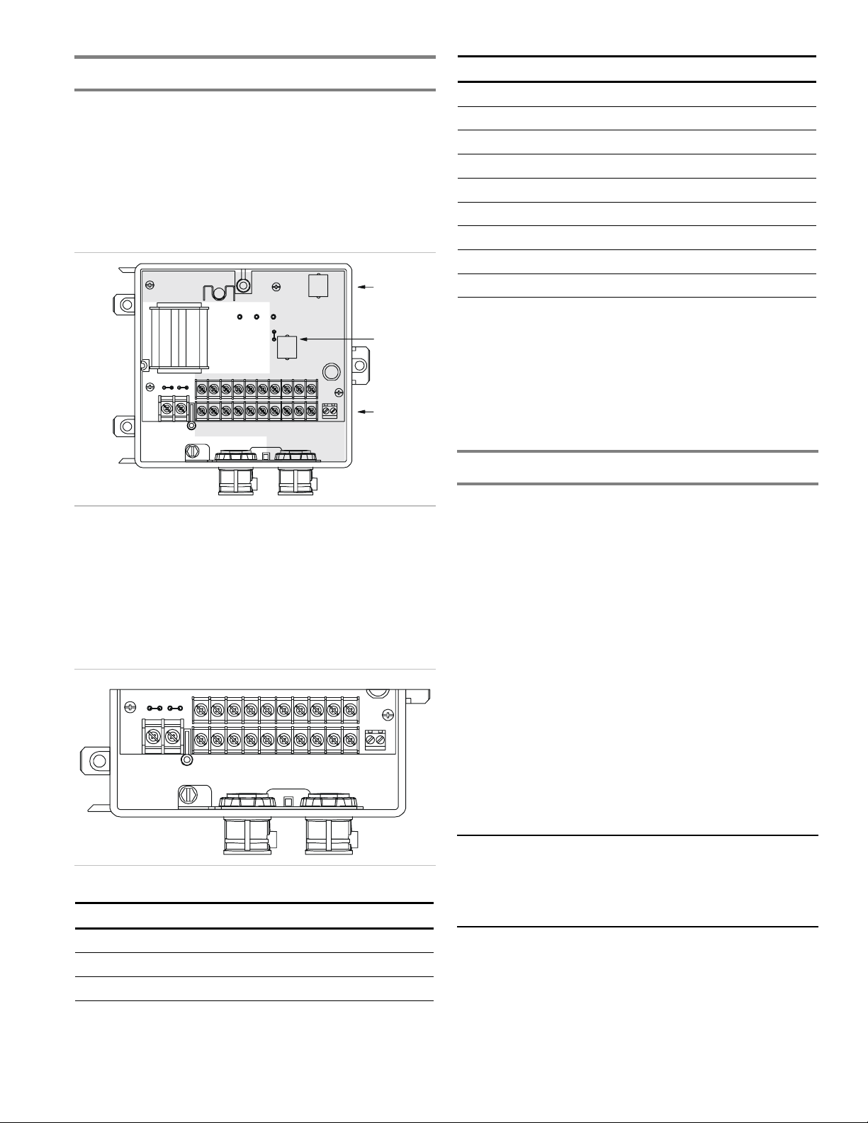
For the test/reset station to indicate the results of the sensor
dirty test, it must be wired to the controller as shown in Figure
13 and the sensor dirty test must be configured to operate the

Technical Bulletin
SuperDuct Four-Wire Duct Smoke Detector 11
controller’s supervision relay. For more information, see
“Changing sensor dirty test operation.”
Caution: Leaving the test/reset station’s key switch in the
RESET/TEST position for longer than seven seconds will put
the duct detector into the alarm state and activate all automatic
alarm responses.
To perform the dirty test using an SD-TRK4:
1. Turn the key switch to the RESET/TEST position for two
seconds. Verify that the test/reset station’s Trouble LED
flashes.
Caution: Holding the test magnet to the target area for longer
than seven seconds will put the duct detector into the alarm
state and activate all automatic alarm responses.
To perform the dirty test using an SD-TRM4:
1. Hold the test magnet to the target area for two seconds.
Verify that the test/reset station’s Trouble LED flashes.
Troubleshooting
Controller’s Trouble LED is on
1. Check the Trouble LED on each sensor connected to the
controller. If a sensor’s Trouble LED is on, determine the
cause and make the necessary repairs.
2. Check the wiring between the sensor and the controller. If
wiring is loose or missing, repair or replace as required.
Controller’s Trouble LED is flashing
1. One or both of the sensors is 100% dirty. Determine
which one’s Dirty LED is flashing then clean that sensor
assembly as described in this documentation.
Sensor’s Trouble LED is on
1. Check the sensor’s Dirty LED. If it is flashing, the sensor
is dirty and must be cleaned.
2. Check the sensor’s cover. If it is loose or missing, secure
the cover to the sensor housing.
3. Replace sensor assembly.
Sensor’s Power LED is off
1. Check the controller’s Power LED. If it is off, determine
why the controller does not have power and make the
necessary repairs
2. Check the wiring between the sensor and the controller. If
wiring is loose or missing, repair or replace as required.
Controller’s Power LED is off
1. Make sure the circuit supplying power to the controller is
operational. If not, make sure JP2 and JP3 are set
correctly on the controller before applying power.
2. Verify that power is applied to the controller’s supply
input terminals. If power is not present, replace or repair
wiring as required.
Remote test/reset station’s Trouble LED does not flash
when performing a dirty test but the controller’s Trouble
LED does
1. Verify that the remote test/station is wired as shown in
Figure 13. Repair or replace loose or missing wiring.
2. Configure the sensor dirty test to activate the controller’s
supervision relay. See “Changing sensor dirty test
operation.”
Sensor’s Trouble LED is on but the controller’s Trouble
LED is off
1. Remove JP1 on the controller.
Cleaning the duct smoke sensor
Clean the duct smoke sensor when the Dirty LED is flashing
continuously or sooner if conditions warrant.
Caution: If the duct smoke detector is connected to a fire
alarm system, first notify the proper authorities that the
detector is undergoing maintenance then disable the relevant
circuit to avoid generating a false alarm.
Airflow
HVAC duct
Sampling
tube
Retainer
clip
Optic
plate
Optic
housing
Sensor
housing
Figure 11: Sensor cleaning diagram
To clean the duct smoke sensor:
1. Disconnect power from the duct detector then remove the
sensor’s cover.

Technical Bulletin
12 SuperDuct Four-Wire Duct Smoke Detector
2. Using a vacuum cleaner, clean compressed air, or a soft
bristle brush, remove loose dirt and debris from inside the
sensor housing and cover.
Use isopropyl alcohol and a lint-free cloth to remove dirt
and other contaminants from the gasket on the sensor’s
cover
3. Squeeze the retainer clips on both sides of the optic
housing then lift the housing away from the printed circuit
board.
4. Gently remove dirt and debris from around the optic plate
and inside the optic housing.
5. Replace the optic housing and sensor cover.
6. Connect power to the duct detector then perform a sensor
alarm test.

Technical Bulletin
SuperDuct Four-Wire Duct Smoke Detector 13
8.706
7.750
8.150
2.275
5.450
5.400
1.375
2.275
5.450
5.800
6.200
6.756
1.900
1.900
1.100
3.250
Figure 12: Mechanical dimensions

Technical Bulletin
14 SuperDuct Four-Wire Duct Smoke Detector
5.4001.375
1.900
13.55
13.95
14.51
2.72
5.45
Figure 12: Mechanical dimensions (continued)

Technical Bulletin
SuperDuct Four-Wire Duct Smoke Detector 15
1
12
2
1
14
13
19
15
2
20
3
10
9
J1
J2
RJ-45 cable [9]
RJ-45 cable [9]
1st sensor
2nd sensor [1]
J1
J1
Reset/Test
Trouble
Power
Alarm
SD-TRK4 or SD-TRM4 [6]
L
N
L
N
17
7
6
18
16
8
Auxiliary
equipment
Auxiliary
equipment
Supervision relay
contacts [3]
First controller
5
4
Alarm initiation
contacts [2]
5
4
Alarm initiation
contacts [2]
5
4
1
3
2
1
12
14
13
19
15
2
20
3
10
9
J1
J2
Reset/Test
Trouble
Power
Alarm
17
7
6
18
16
8
Supervision relay
contacts [3]
Last controller
5
4
1
3
2
Supervision relay
(supplied by installer)
Supervision relay
(supplied by installer)
EOLR [4]
(supplied by installer)
RJ-45 cable [9]
RJ-45 cable [9]
1st sensor
2nd sensor [1]
J1
J1
JP1
JP2 JP3
120V
230V
JP2 JP3
120 V
230V
JP1
SD-TRK4 or SD-TRM4 [6]
Multiple fan shutdown [8]
TB3
Auxiliary
equipment 2
1
TB3
+
−
+
−
Auxiliary
equipment
Auxiliary
equipment
+
−
Initiating device circuit
on fire alarm
control panel [7]
120V/220V/240V [5]
TSD-CO2 module
output [10]
TSD-CO2 module
output [10]
24V AC/DC24V AC/DC
120V/220V/240V [5]
18 Vdc ( )
+
18 Vdc ( )
−
18 Vdc ( )
+
18 Vdc ( )
−
Notes
[1] Remove JP1 when the controller is
connected to two sensors
[2] Alarm initiation contacts shown in normal
condition. Contacts close on alarm.
[3] Supervision relay contacts shown in
normal condition. Contacts change over on
sensor or controller trouble.
[4] End-of-line resistor required on last
controller only. Value is determined by the
fire alarm control panel.
[5] Move JP3 to the 230V position only
when using 220V or 240V to operate the
controller
[6] No more than two remote test/reset
stations can be connected at the same time.
Wiring is nonsupervised. Maximum wire
resistance is 10 ohms per wire.
[7] Control panel provides supervision and
determines wire requirements
[8] Wiring is nonsupervised. Wire resistance
from first controller to last controller can not
exceed 5 ohms.15 controllers, max.
[9] Wiring is supervised by the controller.
Maximum wire distance is 100 ft.
[10] TSD-C02 module has not been
performance evaluated to UL 2075
+
−
Auxiliary
equipment
+
−
Wire must be
added by installer
Wire must be
added by installer
CAUTION
Do not use looped wires under
terminals 5 and 4. Break wire runs
to provide supervision of connections.
CAUTION
Do not use looped wires under
terminals 5 and 4. Break wire runs
to provide supervision of connections.
Figure 13: Duct smoke detector wiring diagram

Technical Bulletin
16 SuperDuct Four-Wire Duct Smoke Detector
This manual suits for next models
18
Table of contents
Other Edwards Signaling Smoke Alarm manuals

Edwards Signaling
Edwards Signaling E-SDPCB Assembly instructions

Edwards Signaling
Edwards Signaling 517TCS Series User manual

Edwards Signaling
Edwards Signaling 517TH Series User manual

Edwards Signaling
Edwards Signaling 517T Series User manual

Edwards Signaling
Edwards Signaling SuperDuct ESD-2W User manual

Edwards Signaling
Edwards Signaling 517TCSB Series User manual

Edwards Signaling
Edwards Signaling SuperDuct TSD-SJ Assembly instructions