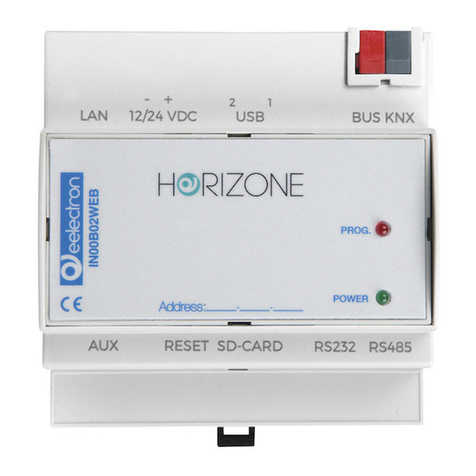
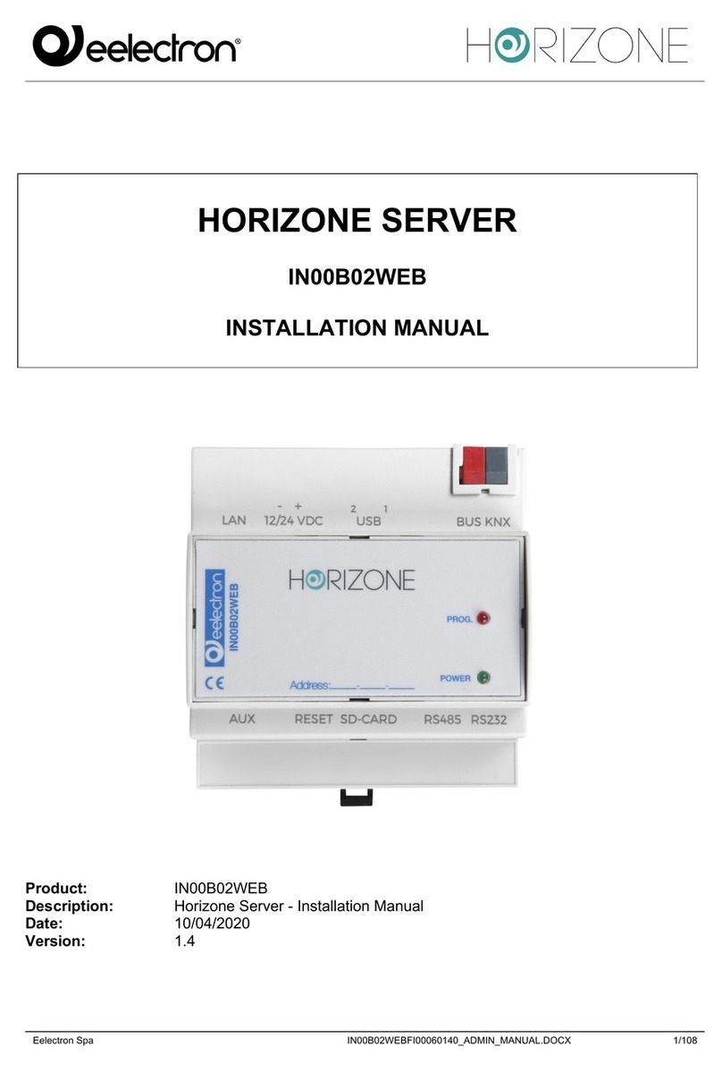
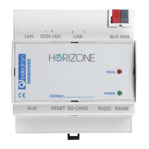
Eelectron HORIZONE User manual

Eelectron Spa
IN00B02WEBFI00060134_MODBUS_MANUAL_IT
1/22
HORIZONE SERVER
IN00B02WEB
MODBUS MODULE MANUAL
Product: IN00B02WEB
Description: Horizone Server Modbus Module Manual
Date: 03/03/2020
Version: 1.3

Eelectron Spa
IN00B02WEBFI00060134_MODBUS_MANUAL_IT
2/22
Any information in this manual may be changed without notice.
This manual can be downloaded free of charge from the website: www.eelectron.com
Exclusion of responsibility:
Although the contents of this manual have been checked to ensure that they correspond to the
hardware and software indicated in the title, changes may, however, be made. Consequently,
Eelectron assumes no responsibility therein.
© 2020 Eelectron SpA. All rights reserved.
Microsoft, Windows, Windows 2000, Windows XP, Windows 2003, Windows Vista, and Internet
Explorer are either registered trademarks or trademarks of Microsoft Corporation in the USA and
other countries. Java is a trademark of Sun Microsystems, Inc. in the USA and other countries.
All other product names mentioned herein are trademarks or registered trademarks of their
respective manufacturers.

Eelectron Spa
IN00B02WEBFI00060134_MODBUS_MANUAL_IT
3/22
Summary
INTRODUCTION 4!
Safety Information 4!
Copyright 4!
INTRODUCTION 5!
Introduction 5!
Purpose of this document 5!
Requirements 5!
CONNECTION 7!
Modbus RTU 7!
Modbus TCP 7!
Preliminary operations 7!
MODBUS LINES 11!
Introduction 11!
New Modbus line 11!
MODBUS REGISTERS 15!
Creation of registers 15!
Multiple reads and writes 20!
Register details 21!
Events and connections 21!
REVISIONS 22!
OPEN SOURCE 22!

Eelectron Spa
IN00B02WEBFI00060134_MODBUS_MANUAL_IT
4/22
INTRODUCTION
Safety Information
This manual contains the information necessary to safely operate the device. Anyone interacting
with the device must first have read this documentation, especially this safety information. This
document supplements and does not replace any safety laws or directives.
The device has been developed using state-of-the-art technologies and following current safety
regulations; it is, however, not possible to totally exclude all possible damage or interaction with other
devices during its operation. The device complies with EMC guidelines and harmonised European
standards; any changes to the device may affect EMC compatibility.
The supply voltage must be strictly within the range indicated in this manual and on the device;
danger of fire or explosion if power is supplied outside this range. The equipment shall be powered
by a limited power supply circuit whose isolation from the mains shall be not less than that between
the primary and secondary circuits of a safety transformer according to IEC 61558-2-6 or equivalent.
The CE declaration of conformity of the device can be requested from Eelectron SpA, at the contacts
on the website www.eelectron.com
In accordance with Directive 2002/96/EC, electronic devices must be disposed of in
dedicated facilities and not in the collection of municipal solid waste.
Copyright
HORIZONE SERVER technical instructions, manuals and software are subject to copyright; all rights
are reserved. Copying, reproduction, translation and/or modification, even partial, are expressly
prohibited unless approved in writing by Eelectron SpA.

Eelectron Spa
IN00B02WEBFI00060134_MODBUS_MANUAL_IT
5/22
INTRODUCTION
Introduction
HORIZONE can use the Modbus RTU and Modbus TCP/IP protocol to supervise one or more slave
devices, connected via both RS485 and network connection.
Once communication logs are configured with a Modbus slave device, they can be managed as
objects on the supervision pages or associated with other objects using logic.
Purpose of this document
This manual contains all the information you need to install, configure and use the specific features
of Modbus technology in the HORIZONE SERVER. It is aimed primarily at installers, but can also
be a useful guide for end users who are interested in customising the supervision features of their
building automation system.
It assumes a good knowledge of the Modbus protocol, the related devices to be supervised and
controlled on the system and HORIZONE; many sections of this document refer to general concepts
of supervision that can be explored in the general product INSTALLATION MANUAL.
For more information on the Modbus protocol, please consult the following page:
http://www.modbus.org/tech.php
Requirements
You must have the following in order to manage an integration of Modbus devices with HORIZONE:
● A HORIZONE SERVER
● MODBUS module activation license
To enter the activation license:
● Log on to HORIZONE SERVER administration
● Select “SETUP” from the side menu, then “MANAGE MODULES AND LICENSES”
● Identify “ACCESS CONTROL” and enter the activation code

Eelectron Spa
IN00B02WEBFI00060134_MODBUS_MANUAL_IT
6/22
● Press the “SAVE” button and wait for the page to reload
Refer to the INSTALLATION MANUAL for further details.

Eelectron Spa
IN00B02WEBFI00060134_MODBUS_MANUAL_IT
7/22
CONNECTION
Modbus RTU
To manage a device operating with MODBUS RTU protocol, simply connect it to the RS485 port
integrated into HORIZONE SERVER, respecting the polarity indicated on both the webserver and
the device.
Alternatively, you can use the RS232 port or one of the USB ports, using an RS485 adapter.
Modbus TCP
Interfacing with a device operating on MODBUS TCP protocol requires it be connected to the same
LAN as the webserver and for the two to be able to dialogue on the communication port of the
protocol, typically port 502.
Preliminary operations
Before starting the configuration of a Modbus device in HORIZONE SERVER, it is necessary to
obtain the table (or “mapping”) of the read and/or write logs. You will be able to identify the useful
information in it to make the HORIZONE communicate with the device, including the fundamental
information you need to know before proceeding with the integration:

Eelectron Spa
IN00B02WEBFI00060134_MODBUS_MANUAL_IT
8/22
COMMUNICATION
PARAMETERS
They vary depending on the type of protocol used by the Modbus
device.
In the case of Modbus RTU, the entries are as follows:
- Baud rate
- Parity
- Data bit
- Stop bit
- Communication mode (RS232 or RS485)
With the Modbus TCP, you need to know:
- IP Address
- Port
SLAVE ADDRESS
Each Modbus peripheral, whether communicating via RTU or
TCP, has a unique address on the network.
Unless the manufacturer specifies it, you can change it. The
procedure to follow is specified in the manual and is usually
performed through pre-configuration software of the device or
via hardware with dedicated switches. Eligible addresses on a
Modbus network range from 1 to 247. The Master device of the
line, which in our case will always be HORIZONE, does not need
an address for communication while address 0 is reserved for
“broadcast” messages

Eelectron Spa
IN00B02WEBFI00060134_MODBUS_MANUAL_IT
9/22
FUNCTIONS
In the Modbus, the “Function” entry indicates the second byte of
a message. It is sent by the Master and indicates which table of
Slave logs must be entered to access the data and whether a
read or a write operation should be performed.
Read functions:
FC 01: Read coil status
FC 02: Read input status
FC 03: Read holding register
FC 04: Read input registers
Write functions:
FC 05: Force single coil
FC 06: Preset single register
FC 15: Force multiple coils
FC 16: Preset multiple registers
It is essential to know each device registry on the network with
which Modbus function must be written and read in order to
access the correct data; as with other information, this is also
contained in the device manuals.
REGISTERS
A register contains the data to be read and/or written with
HORIZONE. Each device has a mapping that identifies each
register and declares its contents: a register, for example, may
contain a temperature value, an on/off command or an alarm
signal.
As you can see below, the logs will be the “objects” available to
the user on the supervision page in order to interact with the
device through the Modbus, whether they are read, write or both.
Since they are HORIZONE objects, they can be used for each
of the server functions: schedules, logics, conditions, composite
objects, etc.
For more information, consult the HORIZONE configuration
manual.

Eelectron Spa
IN00B02WEBFI00060134_MODBUS_MANUAL_IT
10/22
DATA TYPES
Indicates the set of values for each register that the variable can
assume and the operations that can be performed on it. For
example, you can only perform simple arithmetic operations on
integers on an integer log (INT).
The device logs table also mainly shows the type of encoding
needed to interpret the value.
Once you have obtained all of the above information about the Modbus device, it is recommended
that you test write and read with Modbus software from your PC. This step allows you to get in-depth
information about the device function by performing a test bench before proceeding with integration
with HORIZONE.
All you need to do is install the Modbus Master software on your PC and connect it with a serial
cable or network cable to the device, depending on whether the protocol is Modbus RTU or TCP, in
order to access the device and its registers. This will allow you to test all the key aspects that will
allow integration: communication parameters, addresses, functions, registers and data types. Once
you have succeeded in interacting with the Modbus device, resolving any problems encountered,
integration on HORIZONE will be easier and faster.
Obviously, this procedure must be followed for each device that you want to insert into a HORIZONE
line.
You can find lots of free Modbus Master programs on the internet; we recommend the following:
http://www.modbustools.com/modbus_poll.html (30 days free trial)
https://oceancontrols.com.au/OCS-011.html
http://www.qmodbus.sourceforge.net/
After obtaining all the information required to integrate one or more Modbus devices with the
HORIZONE and performing the communication, write and read tests, you can proceed to create the
HORIZONE registers.

Eelectron Spa
IN00B02WEBFI00060134_MODBUS_MANUAL_IT
11/22
MODBUS LINES
Introduction
HORIZONE potentially supports more than one Modbus interface, through the creation of the same
number of Modbus lines on different communication channels; these lines can operate
simultaneously, provided they are properly configured on the communication interfaces available in
HORIZONE:
● RS485
● RS232
● USB
● Network
For each line, it is possible to create a number of objects (similar to Modbus registers), belonging to
the different devices connected to it, which can then be entered in the supervision graphics pages.
It is also possible to manage more than one slave device if connected in a “cascade” to the same
RS485 line, thus creating only one line in HORIZONE and differentiating devices through the slave
address, as further detailed below. In this case, all devices must operate with the same
communication parameters (BAUD rate, parity, etc.)
It is essential to create only one bus line for each HORIZONE communication port; otherwise,
communication conflicts will occur.
New Modbus line
Proceed as follows to create a new Modbus line:
● Log on to HORIZONE administration
● Open the “TECHNOLOGIES” section of the side menu
● Select “Modbus” and expand the “Modbus Lines” entry
● Press the “ADD” button in the toolbar below (“+” symbol)
A new bus line is created and added to the list; at this point, by clicking on it and selecting the “three
dots” on the right (or, alternatively, after selecting it, pressing the “EDIT” button in the toolbar), you
access then its configuration page.
In the “GENERAL SETTINGS” section, the following parameters are available, varying depending
on whether the “Communication” entry is set as Serial/USB or Network:

Eelectron Spa
IN00B02WEBFI00060134_MODBUS_MANUAL_IT
12/22
NAME
Modbus Line identifier label
COMMUNICATIONS
Allows the Modbus communication protocol, choosing from:
● Serial/USB
● Network
DEBUG
There are two entries in the Debug field:
● None
● Log File
By selecting “Log file”, all the events that affect the Modbus line, both
in transmission and in reception, with related errors, line settings and
other information will be written to a file, which can be downloaded with
the “Download Log” button.
This tool can be useful during the commissioning of Modbus devices
with HORIZONE but, once the system is operational, it is
recommended to activate it only if strictly necessary (e.g.
maintenance or software modifications).
The “Clear Log” button clears all content written to the log file by
deleting all previously logged messages and reducing their size.
ENABLE MONITOR
BUS
Selecting this option stores all modbus traffic in a temporary file, which
can be accessed via the MONITOR BUS button (only available if this
option is enabled).

Eelectron Spa
IN00B02WEBFI00060134_MODBUS_MANUAL_IT
13/22
The following parameters must be entered for serial communication:
SERIAL PORT
Determines which communication channel HORIZONE will use to
connect to the Modbus devices connected.
You can use any of the serial ports of the HORIZONE:
● External RS232 port
● USB port 1
● USB port 2
When connecting to HORIZONE USB ports, a USB-serial adapter must
be provided.
BAUD RATE
Sets the Modbus channel communication rate in bits/s.
The speed must be the same as the speed of the devices connected to
the HORIZONE server:
● 1200
● 2400
● 4800
● 9600
● 19200
● 38400
● 57600
● 115200
PARITY
Modbus line communication parameter to be selected based on the one
set on the devices with which communication is to take place:
● EVEN
● ODD
● NONE
STATUS BIT
Modbus line communication parameter to be selected based on the one
set on the devices with which communication is to take place

Eelectron Spa
IN00B02WEBFI00060134_MODBUS_MANUAL_IT
14/22
STOP BIT
Modbus line communication parameter to be selected based on the one
set on the devices with which communication is to take place
COMMUNICATION
METHOD
Set RS485 for natively devices operating in RTU mode, vice versa use
RS232 mode for converters or other similar types of serial
communication interfaces
Conversely, in the case of network communication:
IP ADDRESS
IP address of the Modbus device.
PORT
Communication port used by the Modbus device.
The “Execution status” entry tells the user the status of the Modbus line: “running (continuous) if
there is communication, “Stopped” if there is no packet transmission and reception.
There are two buttons to intervene on line communication: “START” and “STOP” that respectively
allow you to start or stop communication with the Modbus line.
There are also three other buttons available: “CLOSE”, which simply closes the open Modbus line
page, “DOWNLOAD LOG” and “CLEAR LOG”.
The “DOWNLOAD LOG” and “CLEAR LOG” buttons appear only if the Debug entry has been
enabled in the properties. By pressing the “DOWNLOAD LOG" button, the browser will start
downloading the file containing all the events that will affect the Modbus line, both in transmission
and reception, with related errors, line settings and other useful information.
The “CLEAR LOG” button clears the contents of the Log file by deleting all previously logged
messages and reducing the size.
The “Enable Communication” flag, if not selected, allows you to maintain the configuration of a bus
line within the project, but make communication inert.

Eelectron Spa
IN00B02WEBFI00060134_MODBUS_MANUAL_IT
15/22
MODBUS REGISTERS
Creation of registers
To create one or more registers for each slave connected to the HORIZONE Modbus line:
● Access the Modbus Line
● Type the number of registers to create in the text field next to the “ADD” button under the
section title “MODBUS REGISTERS”
● Press the ADD button
As many new registers as required are automatically created.
Once created, the registers can be renamed simply by typing the new name in the appropriate text
box; You can also access the register detail tab, through the corresponding edit button; the
“DELETE” button vice versa removes (permanently) the register from the project.
For each register, you can set the following properties:
NAME
Label used within the supervision to identify the Modbus Slave register.
E.g. “outdoor temperature”, “living room light” etc.
SLAVE
Address of the Slave device to which the register belongs.
REGISTER
Register address.
TYPE
Determines the type of data contained in the register:
● Boolean (ON/OFF)
● Numeric - rational (with comma)
● Numeric - integer (no comma values)
Note: we recommend using integer encoding if you do not expect
comma values to be handled.
READABLE
Flag to enable if the register can be read.

Eelectron Spa
IN00B02WEBFI00060134_MODBUS_MANUAL_IT
16/22
READ
If the register is readable, determine which Function to query with:
● Read Coil Status (FC1)
● Read Input Register (FC2)
● Read Holding Registers (FC3)
● Read Input Registers (FC4)
WRITABLE
Flags to enable if the log is writable.
WRITE
If the register is in write, choose the appropriate Function to run it:
● FC05 (Force Single Coil)
● Preset Single Register (FC06)
● Force Multiple Coils (FC15)
● Preset Multiple Registers (FC16)
R/W
Allows you to determine the number of registers to be read and/or
written simultaneously. For further details, please refer to the
appropriate section below

Eelectron Spa
IN00B02WEBFI00060134_MODBUS_MANUAL_IT
17/22
ENCODING
Determines the type of encoding to be used for interpreting the data
within the register. The following encodings are supported:
Unsigned Integer
Unsigned integer
1 register (2 bytes)
Signed Integer
Signed integer
1 register (2 bytes)
Unsigned long
Unsigned Long
2 registers (2 bytes) *
Signed Long
Signed long
2 registers (4 bytes) *
Signed long inverted
Signed long inverted
Note: the order of the
two registers is
reversed with respect to
the “long” encoding
2 registers (4 bytes) *
Floating point
2 registers (4 bytes) *
Inverted floating point
Note: the order of the
two registers is
reversed with respect
to the "floating point"
encoding
2 registers (4 bytes) *
Bit mask
Bit mask
1 register (2 bytes)

Eelectron Spa
IN00B02WEBFI00060134_MODBUS_MANUAL_IT
18/22
Signed double
Signed double
4 registers (8 bytes)
Unsigned double
Unsigned double
4 registers (8 bytes)
(*) in order to be selected, 4-byte encodings require the R/W field be
set to “2” beforehand, since two registers must be read/written
together. Similarly, the field must be set to 4 for 8-byte encodings.

Eelectron Spa
IN00B02WEBFI00060134_MODBUS_MANUAL_IT
19/22
BIT
This entry is available only if the register on which you write and read is
encoded as Bit Mask.
This encoding is used where each individual bit has a precise meaning
(e.g. a one-byte register where each individual bit is an on/off output of
an 8-channel actuator).
The Bit entry then determines on which bit within the mask the read
and/or write operation will be performed.
MULTIPLIER
The contents of the register are multiplied by the value set in this field.
E.g. register (temperature): 235;
multiplier: 10;
value on HORIZON: 235x10 = 23.5
OFFSET
Allows you to add a fixed value to the value read by the device.
E.g. register (temperature): 235;
multiplier: 10;
offset: 10;
value on HORIZON: 235x10 - 20 = 3.5
COV
In the case of numerical encodings, it allows you to set a threshold,
below which variations in value are ignored and not “propagated” within
the supervision.
Note: for decimal values, use the period as the separator
STATUS
Current register value.

Eelectron Spa
IN00B02WEBFI00060134_MODBUS_MANUAL_IT
20/22
ICON
Choice of graphic set to display in the Frontend register.
Lets you choose which icon to use in HORIZONE's “FRONTEND” to
graphically represent the register.
The library of available icons depends on the selection of the register
type (Boolean or Numerical).
Press the “UPDATE" button to the left of the Modbus Registers bar to confirm the creation or changes
of the logs and make them active. Once the communication has started, the coloured indicator in the
COM column indicates whether the register is reachable or not.
Multiple reads and writes
It is possible to read and/or write simultaneously to more than one register; this option is necessary
(setting the value “2”) for registers that adopt 4-byte encoding, but more generally it can be used (if
the slave device supports it) to operate on contiguous registers with a single read/write operation,
thus speeding up communication.
To activate a multiple read/write, enter a value other than “1” in the R/W field; the same number of
“sub-objects” are automatically created (with respect to the main register) as the number of
read/write set, automatically configured with the registers adjacent to the first:
Sub-objects must share some attributes with the former, such as read/write flags and encoding.
Conversely, it is possible to enter the multiplication factor, COV and icon set independently, since
they represent independent values in the graphic supervision (which could also represent quantities
of different types).
Other manuals for HORIZONE
1
This manual suits for next models
1
Table of contents
Other Eelectron Server manuals
