Eelink TK419 Series User manual

1
4G LTE FDD GNSSTRACKER
For Vehicle
<GPS+GSM+WCDMA+LTE FDD+SOS/Battery/iButton/BLE>
User Manual
MODEL:TK419-S/B/I/T/BLE
-Professional Tracking System --

2
CATLOG
Ⅰ. Product Features.............................5
Ⅱ. Components and Accessories.....7
Ⅲ. SIM card Installation.....................9
Ⅳ. Device Installation...................... 10
4.1 Install Device........................ 10
4.2 Device Wiring Definition......11
4.3 Relay Wiring......................... 14
Ⅴ. Power On / Off............................. 15
5.1 Power On.............................. 15
5.2 LED Indicators......................15
5.3 Power Off..............................16
Ⅵ. Inquiry/Monitoring/Cut Oil......... 16
6.1 Inquiry by Service Platform..16
6.2 Inquiry by SMS.....................17
6.3 Cut Oil /Restore.................... 17
Ⅶ. Device Alarm.............................. 17
7.1 SOS Alarm............................ 17

3
7.2 Vibration Alarm.................... 17
7.3 Shock Alarm..........................18
7.4 Speed Alarm..........................18
7.5 Shift Alarm............................19
7.6 Geo-fence Alarm...................19
7.7 Power Disconnect Alarm...... 19
7.8 Low Battery Alarm............... 19
Ⅷ. Device Setting........................... 20
Ⅸ. Trouble shooting.........................20
9.1 Cannot connect platform.......20
9.2 Offline Status........................ 20
9.3 No Positioned........................21
9.4 Position Drift.........................22
9.5 Commands Receiving
abnormally.................................. 22
Ⅹ. Warranty Rules............................ 22
10.1 Special Statement................22
10.2 Warranty Period.................. 23
10.3 After Sales...........................23

4
Welcome to use our device, please read this
manual carefully to install and operate device
exactly. This user manual is for reference only.
If some contents and operation steps are
inconsistent with those for the actual product,
the latter will prevail.
With TK419 GNSS Tracker, we can monitor
your vehicle by GNSS satellite positioning
system, GPRS/WCDMA/LTE FDD network
communication and Internet, a real-time
remote location and control of vehicles can be
achieved through a powerful service platform.
It plays a significant role in logistics and cold
chain, helping customers to achieve
transparent management, reduce costs,
ensure safety, and improve efficiency.

5
Ⅰ. Product Features
■Support GSM/ WCDMA/ LTE FDD
■Support GPS/ Beidou/ Glonass/ Galileo/
Qzss. A-GNSS/ LBS for aiding.
■Data Uploaded by GPRS/WCDMA/LTE
FDD regularly, check by Web/APP/SMS.
■Super Wide Input Voltage:9-72V DC
■ACC status detection
■Support SOS, External battery, iButton,
Bluetooth host
(Hardware customization, Choose one of 5)
■Support Serial port or GPIO port
■Built-in battery, power disconnect alarm &
low battery alarm.
■Built-in motion sensor, support shock
alarm include vibration, collision and falling.
■GEO-fence alarm, speed & shift alarm.
■Relay to cut engine, auto cut engine when
over speed and recover when normal speed.
■EELINK protocol 2.0, Firmware OTA
■USB connect with PC to configure device
■Waterproof level IP65

6
Basic Specifications
Voltage
12/ 24/ 36/ 48/ 60/ 72 VDC
Work Current
GPRS(500mA);WCDMA(700mA);
LTE(800mA)
Standby Current
Power off(20uA);Sleep(3mA);Idel(22mA)
Satellite Accuracy
5-15m
LBS Accuracy
>100m
GNSSBand
1575MHz
GSM Band
B2/B3/B5/B8
WCDMA Band
B1/B2/B5/B8
LTE Band
FDD(B1/B2/B3/B4/B5/B7/B8
/B28); TDD(B40)
Working Temperature
& humidity
-20℃~75℃; 20%~90% RH
Hot/warm/cold Start
<3s, <26 s, <35 s
Battery Capacity
140mAh
Dimensions (mm)
89(L)X 37(W) X 12(H)
Net Weight
46g

7
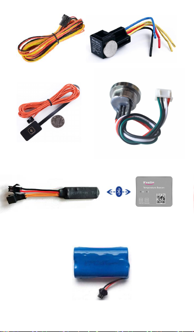
Ⅱ. Components and Accessories
■Components
-Top Front- (Towards sky)
-Bottom -
■Accessories
Relay for remotely cut engine, SOS button used for
sos help, External battery used for power supplier,
iButton can be used for interactive functions such
as driver's identification;Temperature sensor used
monitoring temperature data; External Bluetooth
can be as a beacon host;
8
Power Cable(Default) Relay PIN4(Optional)
SOS PIN7/8(Default Optional) iButton PIN7/8(Optional)
Bluetooth PIN 5/6/7/8(Optional) BEACON(Optional)
External Battery PIN 7/8(Optional)
9
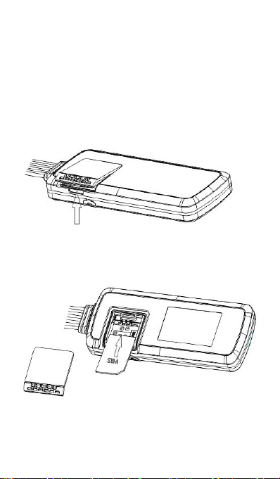
Ⅲ. SIM Card Installation
Open the packing case, check if device is OK
and accessories are intact,
You need a suitable SIM card for using device,
contact your dealer if any question;
Open SIM Card cover
Put SIM Card and waterproof rubber
10
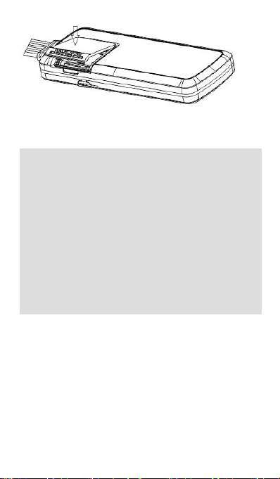
Press cover and close
Note:
●Please cut off the power before installing or
uninstalling SIM card.
●SIM card should have GPRS/WCDMA/LTE
function, open it’s network through operator.
●SIM card should open Caller Identification function
for telephone querying.
●If you enable the PIN code of the SIM card,
please use your mobile phone to disable it.
●Please make sure SIM card has sufficient
balance.
Ⅳ. Device Installation
4.1 Install Device
4.1.1 Please install device concealed by
professional person
Please make sure to install device with up side
upward, and use wide strong double-sided
adhesive sponge to fix it.

11
4.1.2 Installation Notice
●Hide device properly inside the car body in order
to avoid damages.
●Keep device away from RF emission sources
such as backing radar, car burglar alarm and other
vehicle mounted communication devices.
●Suggest to use wide strong double-sided
adhesive sponge to fix it, or use cable ties and
other liable methods to fix it.
●Device Built-in GSM/WCDMA/LTE antenna and
GNSSantenna, Please ensure that signal receiving
side is facing up(towards the sky) when doing
installation, without any metal material covered on
the top.It may weaken signal and results in not work
properly.
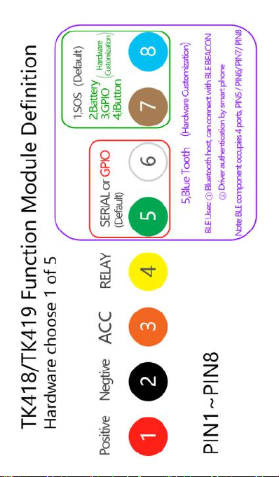
4.2 Device wiring definition
12
13
Total schematic wiring device
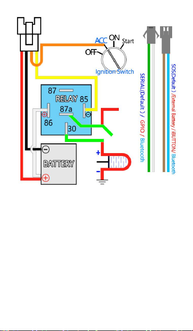
4.2.1 Power cables and interface
The standard input voltage of device is 9V-72VDC,
so please choose the our original power cables, the
red cable is positive and the black cable is negative;
Please ground negative pole separately or ground it
to ground connection, not to any other ground.
Connect the ACC cable (orange cable) to ACC
switch of the vehicle, the position server will get
ignition status of vehicle; the ACC cable can also be
connected directly to the positive pole of the vehicle

14
power, then the position server think that the vehicle
is always ignited.
Connect the 4# cable (yellow cable) to the 85
device(with small yellow cable) of the relay. Use
cable ties to fix the relay to waterproof place, or use
plastic bags cover the relay.
Connect SOS/Battery/iButton with PIN7 & PIN8.
4.3 Relay wiring
Relay wiring diagram shows how to wire the relay to
control the fuel pump:
4.3.1 Connect the 86 port to the positive pole of the
vehicle power (+12V/+24V), connect the 85 port to
the 4# cable of device.
4.3.2 Cut off the positive pole of the fuel pump, next
serial connect the positive pole to the 87a port of
the relay, and connect another pole to 30 port,
showing as in the figure.
Bottom of the relay Wiring Diagram

15
Notice: Be sure the voltage of the vehicle power
should match up to the working voltage of relay, or
relay maybe damaged.
Ⅴ. Power On / Off
5.1 Power on
Power on: insert a valid SIM card and wire all the
cables, device will power on.
5.2 LED Indicators
The red LED flickers fast when device is searching
for GSM/LTE network, it flickers intermittently when
device has registered the GSM/LTE network
successfully.
The blue LED flickers fast when device is searching
for the GNSSsatellite signal, it flickers intermittently
when device has searched the satellites and can be
positioned.
Red LED / GSM/WCDMA/LTE
Blue LED / GNSS

16
1. Red LED(indicates GSM/WCDMA/LTE state)
Fast blinking
Searching for
GSM/LTE network
Slow blinking
GSM/LTE works
normally
2. Blue LED(indicates GNSSstate)
Fast blinking
Searching
GNSSSatellites
Slow blinking
GNSSworks normally
5.3 Power off
Disconnect the external power and take off SIM
card, after a while device will shut down.
Ⅵ. Inquiry/Monitoring/Cut Oil
6.1 Inquiry by Service Platform
6.1.1 Web Browser platform
Login the service platform and enter your ID and
password to check the position of device. Please
ask your dealer for the WWW address of the
position service platform.
6.2.2 Smart phone applications
You can use a smart phone to check device’s
position. We have prepare for you the Android client
(Android), Apple clients (IOS), please check with

17
your dealer to get installation package.
6.2 Inquiry by SMS
You can write a positioning SMS sending to device
to inquiry position, device will reply position SMS or
map link. The SMS commands please refer to the
Operation Commands 2.0
6.3 Cut Engine/Restore
6.3.1 Cut off oil circuits
Server(GPRS/WCDMA/LTE) or Manager number
(SMS) can send cut-fuel-circuit commands to
device when needed. Engine can not start, vehicle
will be locked.
To make sure safety of vehicle, fuel of vehicle Can
be cut off only if device has been positioned by
GNSSand speed of vehicle is less than 20KM/h or
vehicle is static.
6.3.2 Recover oil circuits
Server(GPRS/WCDMA/LTE) or Manager number
(SMS) can send recover-fuel-circuit commands to
device when needed, device will recover fuel
circuits of vehicle.
Ⅶ. Device Alarm
7.1 SOS Alarm
Conditions: When SOS button is long pressed for 3

18
seconds.
Note: SOS button must be installed (optional
accessory), and SOS administrator number must be
set. When the SOS alarm occurs, device will dial
the set SOS administrator number 3 times until
getting through.
Note: When above alarm occurs, Device will send
alarm to service platform, meanwhile send a SMS
message to administrator number if this number
was set.
7.2 Vibration Alarm
Conditions: When Vehicle Vibration occurs.
Note: You need to set vibration sensitivity and time,
there is an alarm switch.
7.3 Shock Alarm
Conditions: When Vehicle’s acceleration achieve a
value.
Note: You need to set the acceleration value
threshold.
7.4 Speed Alarm/Cut engine when
over speed
Alarm Conditions: When vehicle speed over and
below the setting speed.
Cut engine Conditions: Cut engine when over
speed (Restore engine when speed recover)
Note: You can set a low speed or a high speed

19
value, also an over-speed value to cut engine
7.5 Shift Alarm
Conditions: When vehicle occur a setting shift in the
Flameout status.
Note: Only valid in flameout state and vehicle occur
a setting shift distance.
7.6 Geo-fence Alarm
Conditions: when the vehicle entry / exit / across
the Geo-fence.
Note: You need to set the conditions of crossing
fence, fence types and so on.
7.7 Power Disconnect Alarm
Conditions: When the device is disconnected from
external Power.
7.8 Low Battery Alarm
Conditions: When the device is disconnected from
external Power and built-in battery power falls
below a certain value .
Note: Alarm parameters must be set in 7.1~7.6,
Please refer to the <Operation Commands 2.0>
Note: When above alarm occurs, device will send
alarm to service platform, meanwhile send a SMS
message to the administrator number if it was set.

20
Ⅷ. Device Setting
Please refer to <Operation Commands 2.0>
Ⅸ. Trouble shooting
9.1 Cannot connect platform
device is never online on the position server when
installed at the first time. Please check device:
1)If power cables are wired correctly? Pay attention
to not connect them to controlling cables of vehicle.
2)If SIM card is installed correctly? Please refer to
the installation instructions.
3)Check the status of LED indicators. If device is
OK, red LED and blue LED will intermittently flick.
4)Inquiry parameters of device via commands and
check replied parameters.
9.2 Offline status
First check if LED indicators are OK, if cannot
check them, you can check SIM card following next
steps:
1)Call SIM card of device and check if you can
hear connecting ring.
2)Check if vehicle is in the area where there is no
This manual suits for next models
5
Table of contents
Popular Automobile Accessories manuals by other brands

Thule
Thule Rapid System 777 Fitting instructions

Whispbar
Whispbar K157W Fitting instructions

AUSSIE TONNEAU
AUSSIE TONNEAU ATR01011 installation instructions

Continental Refrigerator
Continental Refrigerator AIH-CONTI installation guide

Monoflex
Monoflex 03.6020 quick start guide

Dynojet
Dynojet Power commander V installation guide


