EF EFCH6301 HM SS User manual

For original parts & reliable service :
Casa(S)Pte Ltd
15 Kian Teck Crescent Singapore 628884
15
Kian
Teck Crescent Singapore 628884
For after sales service support,please contact
our hotline: + 65 6268 0077
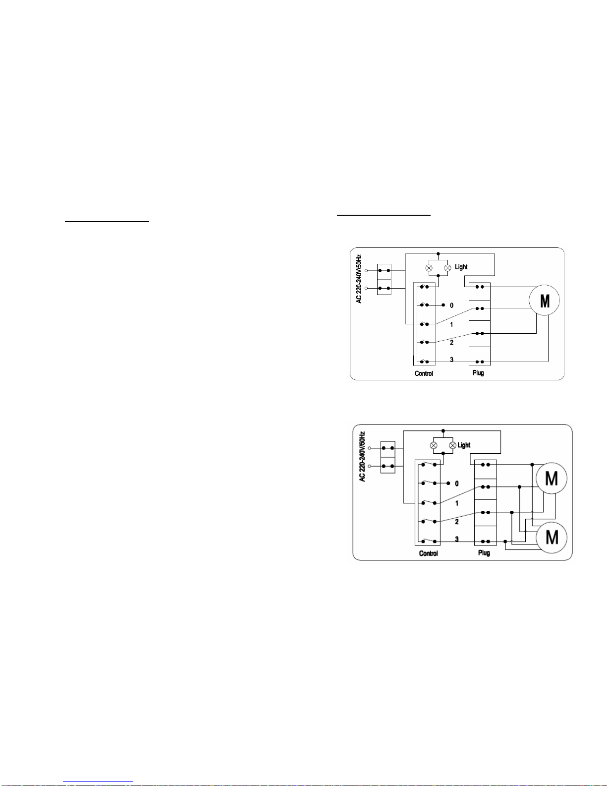
Table of Contents
• From the Manufacturer 3
• Specifications 3
• SAFETY : Read this first ! 4, 5
• Vent System Requirement 5
• Description of Parts 6
• Ducted vs. Re-circulating modes 7
• Installation 8, 9, 10
• Electrical Connection 11
• Operation 12
• Cleaning & Maintenance 13
• Troubleshooting 14
• Schematic Diagram 15
2
Schematic Diagram
1 motor version:
2 motor version:
15
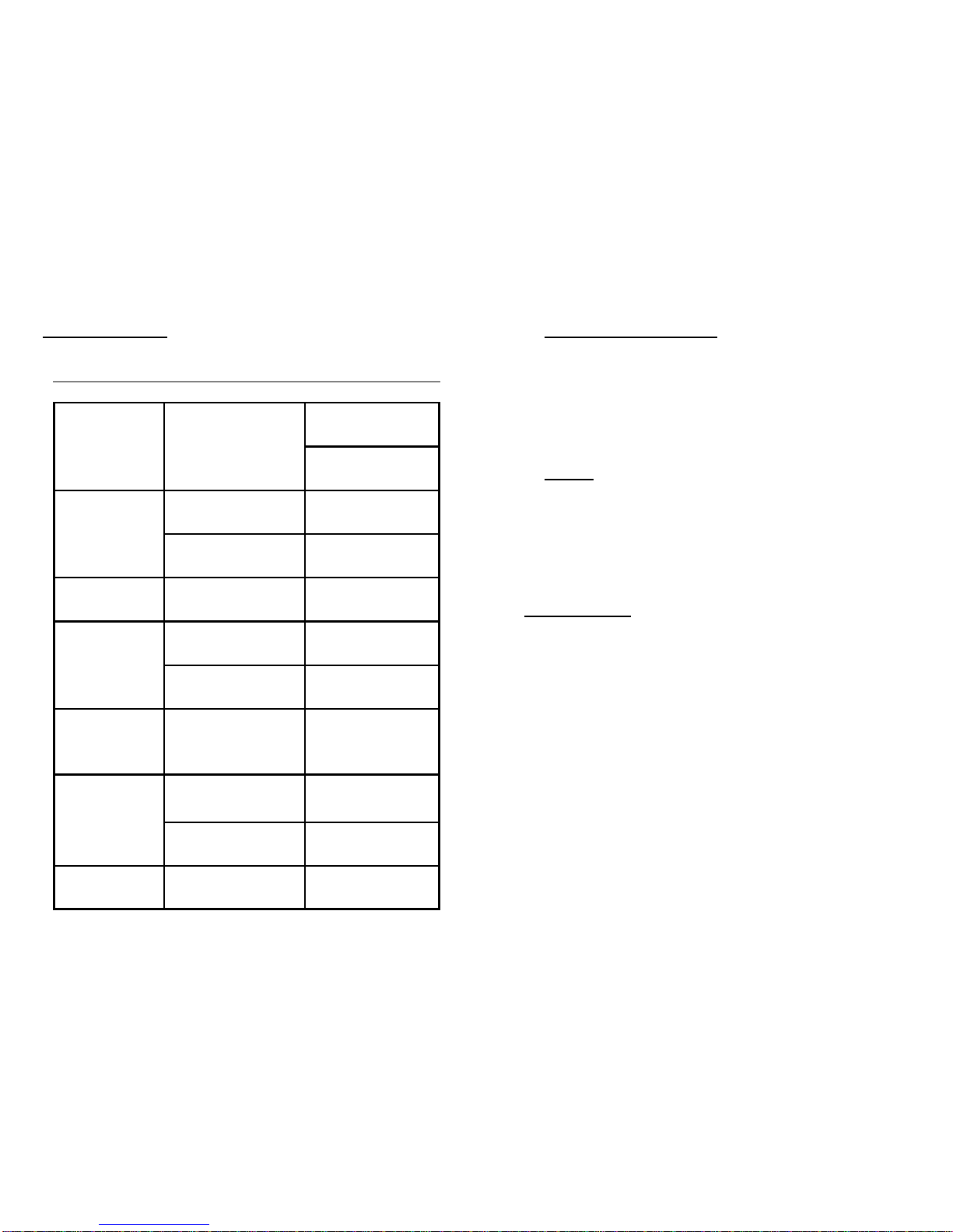
Troubleshooting
14
Symptoms Possible Cause Action
Check that the plug
Does not function No electrical supply is connected.
Check that the main
switch is turned on.
Aluminum grease Clean the filters and
Poor airflow filters clogged replace when dry
Charcoal grease Replace carbon
filters clogged foam with new sets
Motor running but Butterfly valve Contact technician
no airflow jammed
High temperature The kitchen is not
Motor cuts after a safety device activated sufficiently ventilated
few minutes The hood is installed too The hood must be
near the cooking stove least 65cm from stove
Carbon foam not In re-circulating mode,
Strong cooking installed Carbon foam must be
smell installed
Aluminum grease filter Wash the aluminum
Oil dripping onto
stove saturated grease filters
Aluminum grease filter Wash the aluminum
saturated grease filters
Whirring sound Foreign object in contact Contact technician
with fan blade
• From the Manufacturer
• This appliance and it’s packaging are produced by
processes that minimize waste and respect the
environment.
• Please help us to continue the protection of the
environment by disposing of the packaging in a correct
manner.
• Safety !
• Please do not allow young children to play with the plastic
bag packaging.
• Before disposing of any old appliances, be sure to cut off
the power chord so that others will not be endangered by a
defective electric appliance
Specifications
Input : 220-240V 50Hz
Absorption
• 2 motor version : 2 X 85W
• 1 motor version : 1 X 10⁵W
Lamps : 2 X 40W
Total Power
• 2 motor version : 250W
• 1 motor version : 185W
External Dimensions
• 60cm version : 598x495x118mm
• 70cm version : 698x495x118mm
• 90cm version : 898x495x118mm
3

SAFETY : Read this First !
• Do not connect the appliance if there are obvious signs of transportation
damage.
• Read this user manual thoroughly before attempting to use this appliance.
• Installation and repair should be attempted only by qualified technical personnel.
• It is dangerous to modify any part of this appliance.
• The manufacturer declines all responsibility in case of failure to adopt proper
safety measures.
• Ensure the location in which this appliance is installed has good, permanent
ventilation.
• The distance between the bench top to the lower part of the hood must not be at
less than 65 cm or higher than 75 cm.
• Use an electrical connector with earth that is correct for your location.
• Check that the voltage in your area is correct before plugging in.
• The electrical connection of this appliance:
Blue = NEUTRAL
Brown = LIVE
• Multiple plugs and extension cables must not be used. Overload is dangerous
and may cause a fire.
• Ensure that the power supply chord is free from any heat source or sharp
objects.
• The appliance should be switched off and the electrical supply disconnected
before any cleaning or maintenance work can be carried out.
• This appliance is not intended for use by persons (including children) with
reduced physical, sensory or mental capabilities, or lack of experience and
knowledge, unless they have been given supervision or instruction concerning
use of the appliance by a person responsible for their safety. Children should be
supervised to ensure that they do not play with the appliance.
• If the supply cord is damaged, it must be replaced by the manufacturer, its
4
Cleaning & Maintenance
SURFACES : Wash with warm soapy water and a soft sponge. Never use
abrasive detergent, scouring pads, steel wool or solvents on any part of this
appliance as this will cause irreparable damage.
Aluminum Grease Filters : Wash in the dishwashers or soak the panels in a
degreasing agent for an hour, then rinse off.
LIGHT BULB REPLACEMENT : Before attempting to replace the light bulb,
make sure that the light switch is turned off. Remove the grease filter to
access the lamp area. Remove the damaged light bulb and replace with an
incandescent oval bulb maximum 40W.
13
12
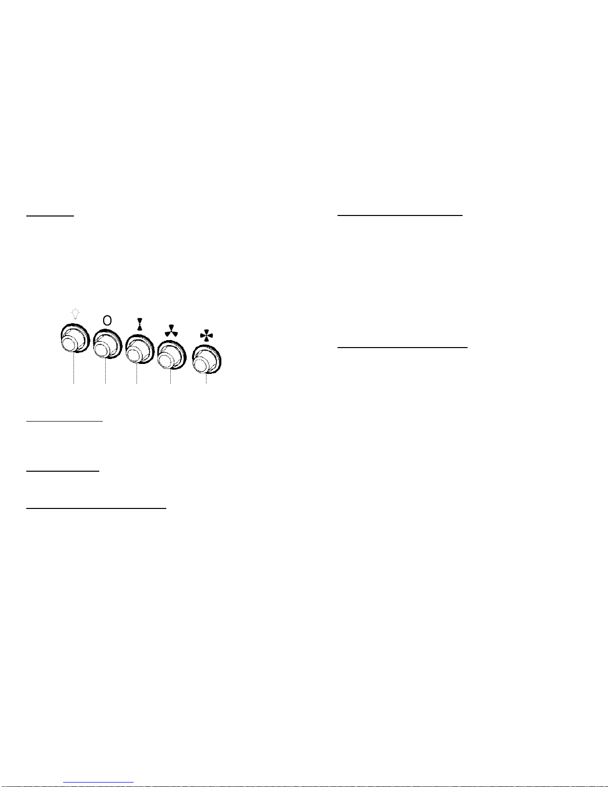
Operation
The hood is equipped with 3 speed control.
Use the low speed for simmering, medium speed for light cooking.
Use the high speed for frying or heavy cooking.
It is also equipped with a light bulb to illuminate you cooking area
when needed.
Light On/Off Button (i)
On/Off switch for the light. Push the button in to turn the light ON,
push again to turn the light OFF.
Blower Off Button (ii)
Off switch for the blower. Push the button in to turn the blower OFF.
Blower On and Speed Buttons (iii, iv & v)
Button (iii) operates the blower on LOW speed.
Push button (iv) for MEDIUM speed.
Push button (v) for HIGH speed.
i ii iii iv v
5
SAFETY : Read this First ! (Continued)
Service agent or similarly qualified persons in order to avoid a hazard.
• There shall be adequate ventilation of the room when the range hood is used at the
same time as appliances burning gas or other fuels (not applicable to appliances that
only discharge the air back into he room);
• There is a fire risk if cleaning is not carried out in according with the instructions.
• Do not flambé under the range hood.
• The appliance use 4 hob element at most.
Vent System Requirements
Determine which venting method is best for your application. Vented (non-re-
circulating) system must be terminate to the outside. Ductwork can extend either
through the wall or the roof. Do not terminate the vent system in an attic or other
enclosed area.
The length of the ductwork and the number of elbows should be kept to a minimum
to provide efficient performance. The size of the ductwork should be uniform. Do
not install two elbows together. Use duct tape to seal all joints in the ductwork
system. Use caulking to seal exterior wall or floor opening around the cap.
Flexible ductwork is not recommended. Flexible ductwork creates back
pressure and air turbulence that greatly reduces performance.
Make sure there is proper clearance within the wall or floor for exhaust duct before
making cutouts. Do not cut a joist or stud unless absolutely necessary. If a joist or
stud must be cut, then a supporting frame must be constructed.
6
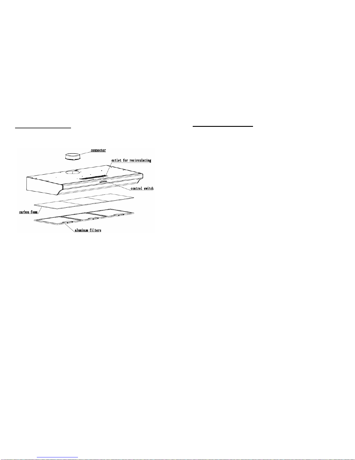
Description of Parts
Electrical Connection
Before completing any connection, make sure the house voltage corresponds
with the voltage indicated on the label affixed inside the hood.
It is advisable to call a qualified technician to make the electrical connection.
Appliance fitted with plug
Connect it to a socket which conforms with current regulations.
If you intend to connect it directly to the electric mains, remove the plug and fit
an approved bipolar switch with a minimum contact opening of not less than
3mm.
If the plug is not accessible once it has been inserted in the socket, it will
however be necessary to fit an approved bipolar switch with a minimum
contact opening of no less than 3mm.
Appliance without plug
Fit an approved plug or an bi-polar switch with a minimum contact opening of
no less than 3mm.
The manufacturer are not liable for any problems caused by the user’s failure
to observe the above instructions
11

10
Installation (2)
STEP 1 : Remove the aluminum filters and place them in a safe location to avoid
damage.
STEP 2 : Hang the hoods first and then Install the 2 screws in the wall through the
inside of the hoods like below picture showed.
STEP 3 : Turn the screws clockwise until locked.
Finished!
7
Ducted vs. Re-circulating modes
Your cooker hood can be configured to operate in the ducted or re-circulating
mode.
A. DUCTED MODE (VENTED MODE)
• In the ducted mode, cooking fumes are vented outdoors through suitable
connection of 125mm diameter. In this mode, only the aluminum filters
are installed, carbon foam is optional.
B. RE-CIRCULATING MODE
• Fumes are filtered for grease and outdoor through the aluminum grease
filters and the charcoal filters respectively and re-introduced into the
kitchen environment. In re-circulating mode, both the aluminum grease
filters and the carbon foam must be installed.

Installation (1)
STEP 1 : Remove the aluminum filters and place them in a safe location to
avoid damage.
STEP 2 : Install the 2 screws on the wall.
8 9
Installation (1) (Continued)
STEP 3 : Hang the hood on the 2 screws.
STEP 4 : Tighten the 2 screws completely.
Finished!
This manual suits for next models
1
Table of contents
Other EF Ventilation Hood manuals

EF
EF EFCH 9211 HM SS User manual

EF
EF EFCH 6201 HM SS User manual

EF
EF EFCH 9402-AL User manual

EF
EF POWER SLIM 90SS User manual

EF
EF POWER SLIM 90X/V User manual

EF
EF CK-SPECCHIO User manual

EF
EF CK-Vetro User manual

EF
EF EFCH 9401 HM SS User manual

EF
EF EFCH9103 HM SS User manual

EF
EF EFCH 9111 910 HM SS User manual


Popular Ventilation Hood manuals by other brands

Gorenje
Gorenje S3 IHGC963S4X manual

KOBE
KOBE ISX2136SQB-1 Installation instructions and operation manual

U.S. Products
U.S. Products ADVANTAGE-100H Information & operating instructions

Kuppersberg
Kuppersberg DUDL 4 LX Technical Passport

Framtid
Framtid HW280 manual

Thermador
Thermador HGEW 36 FS installation manual


