Efapel 40226 User manual

Folheto Informativo n.º 6/2021 (290 304)
REF. 40226 | 40426 S
BOTÃO DE PRESSÃO QUÁDRUPLO D40 - PT
P. 2
BOTÓN DE PRESIÓN CUÁDRUPLO D40 - ES
P. 9
4-GANG PUSH BUTTON D40 - EN
P. 16
POUSSOIR QUADRUPLE D40 - FR
P. 23
4-FACH-TASTER D40 - DE
P. 30

2
PT
BOTÃO DE PRESSÃO QUÁDRUPLO D40
LEGENDA
Botão de Programação
LED de
Modo de Funcionamento (MF)
Botões de Comando
(A|B|C|D)
Botão de RESET
Nota:
Instalação e fixação por parafusos em caixas de aparelhagem (tipo
I1
)
.

3
MODOS DE FUNCIONAMENTO
EM REDE - ONLINE
Não contém atuadores.
Apenas permite comandar outros aparelhos da Série Domus40.
COLOCAÇÃO DO BOTÃO DE PRESSÃO QUÁDRUPLO EM REDE -
ONLINE
1ºPASSO
Pressionar RESET
7” até os LEDs
ficarem todos a
meio brilho.
2ºPASSO
Click em
PROG.
2.1 - O LED MF
começa a piscar,
indicando que está
pronto a ser adicio-
nado à rede, durante
um período de 10” .
1.1 - O LED MF liga.

4
EMPARELHAMENTO DOS APARELHOS JÁ COLOCADOS EM REDE -
ONLINE
NO BOTÃO DE PRESSÃO QUÁDRUPLO
1ºPASSO
Click em PROG
(programação).
1.1- O LED A
liga, indicando que
pode iniciar o EM-
PARELHAMENTO.
3ºPASSO
Click no botão de
comando da Chave
da Instalação (Ref.ª
40925) na proximi-
dade do Botão de
Pressão Quádruplo.
3.1 - O LED começa
a piscar vermelho,
indicando que está à
procura do aparelho a
adicionar.
3.2 - O LED pisca verde
e desliga, o LED MF do
aparelho desliga e os
LEDs A, B, D, Cligam e
desligam em sequência,
indicando que o Botão
de Pressão Quádruplo
foi adicionado à rede
com sucesso.
Nota: No caso do LED da Chave
da Instalação não ficar verde e
desligar, repetir desde o 1º passo.

5
2ºPASSO
Conforme o botão
que deseja em-
parelhar, click A,
B, Cou Dpara
iniciar EMPARELHA-
MENTO.
2.1- O LED Afica a
piscar e todos os apa-
relhos em rede ficam
igualmente a piscar.
Nota: No caso de aparelhos
alimentados a bateria (Ref.ª
40227), o LED não pisca para
maximizar a durabilidade
da bateria.
NOS APARELHOS ATUADORES
3ºPASSO
Para selecionar a
função desejada,
click no botão de
seleção de função
sucessivamente.
3.1 - LEDs indicam
função:
ON - Ligar carga
TG - Comutar
(ON/OFF)
OFF - Desligar
carga
ON|TG|OFF
DESLIGADOS -
Sem EMPARELHA-
MENTO

6
NO BOTÃO DE PRESSÃO QUÁDRUPLO
4ºPASSO
Click em PROG
para concluir o EM-
PARELHAMENTO.
4.1- O LED A apa-
ga, indicando que
pode iniciar o EM-
PARELHAMENTO
está concluído.
Nota: Para localizar o Atuador emparelhado a um botão Emissor, é suficiente reiniciar o
EMPARELHAMENTO (1º PASSO e 2º PASSO). Desta forma, o LED Cdos aparelhos com Atuador
emparelhado fica ligado.

7
CARACTERÍSTICAS
Função - Emissor
Alimentação 230V~ - 50Hz
Temperatura de Funcionamento -5º - +35°C
Tecnologia Rádio Frequência 2.4 GHz
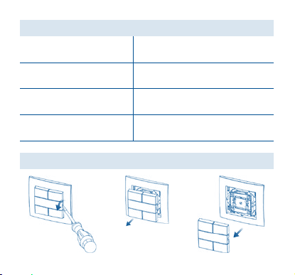
DESMONTAGEM DA TECLA

8
ESQUEMA DE LIGAÇÃO
(ENTRADAS EXTERNAS OPCIONAIS)
L
N
8 mm
1x1,5 mm2
0,6x3,5mmM2,5
DECLARAÇÃO DE CONFORMIDADE UE SIMPLIFICADA
A EFAPEL declara que os equipamentos com rádio pertencentes a este folheto informativo estão
conforme a diretiva 2014/53/UE.
A declaração de conformidade UE completa está disponível no site www.efapel.com/domus40
A EFAPEL reserva o direito de modificar este documento ou os produtos nele contidos sem aviso prévio.
Em caso de dúvida, contacte a EFAPEL.

9
ES
BOTÓN DE PRESIÓN CUÁDRUPLO D40
LEYENDA
Botón de Programación
LED de
Modo de Funcionamiento (MF)
Botones del Mando
(A|B|C|D)
Botón de RESET
Nota:
Instalación y fijación con tornillos en cajas de mecanismos eléctricos (tipo
I1
)
.

10
MODOS DE FUNCIONAMIENTO
EN REDE - ONLINE
No tiene actuadores.
Solo permite controlar otros mecanismos de la Serie Domus40.
COLOCACIÓN DEL BOTÓN DE PRESIÓN CUÁDRUPLO EN RED -
ONLINE
1ER PASO
Presionar RESET 7”
hasta que todos los
LED estén medio en-
cendidos.
2ºPASO
Hacer clic PROG.
2.1 - El LED MF em-
pieza a parpadear,
indicando que está
listo para ser añadi-
do a la red, durante
un período de 10” .
1.1 - El LED MF
se enciende.

11
EMPAREJAMIENTO DE LOS MECANISMOS QUE YA ESTÁN PUESTOS EN RED -
ONLINE
EN EL BOTÓN DE PRESIÓN CUÁDRUPLO
1ER PASO
Hacer clic PROG
(programación).
1.1- El LED A se
enciende, indi-
cando que puede
iniciar el EMPARE-
JAMIENTO.
3ER PASO
Hacer clic en el
botón de control
de la Llave de
Instalación (Ref.
40925) cerca del
Botón de Presión
Cuádruplo.
3.1 - El LED empieza a
parpadear rojo indicando
que está buscando el me-
canismo que va añadir.
3.2 - El LED parpadea
verde y se apaga, el
LED MF do mecanismo
apaga y los LEDs A,
B, D, Cse encienden y
apagan en secuencia,
indicando que el Botón
de Presión Cuádruplo ha
sido añadido a la red
con éxito.
Nota: Si el LED de la Llave de
Instalación no se pone verde
apagar y repetir desde el 1
er
paso.

12
2ºPASO
En función del
botón que quiere
emparejar, haga
clic en A, B, Co
Dpara iniciar EM-
PAREJAMIENTO.
2.1- El LED Ase
queda parpade-
ando y todos los
mecanismos en red
también empiezan
a parpadear.
Nota: En el caso de mecan-
ismos alimentados con bat-
ería (Ref. 40227), el LED no
parpadea para maximizar la
durabilidad de la batería.
EN LOS MECANISMOS ACTUADORES
3ºPASO
Para seleccionar la
función deseada,
hacer clic en el
botón de selección
de función sucesiva-
mente.
3.1 - Los LED
indican función:
ON - Conectar
carga
TG - Conmutar
(ON/OFF)
OFF - Desconectar
carga
ON|TG|OFF
APAGADOS - Sin
EMPAREJAMIENTO

13
EN EL BOTÓN DE PRESIÓN CUÁDRUPLO
4ºPASO
Hacer clic PROG
para finalizar el EM-
PAREJAMIENTO.
4.1- El LED Ase
apaga, indicando
que el EMPARE-
JAMIENTO ha fi-
nalizado.
Nota: Para localizar el Actuador emparejado a un botón Emisor es suficiente con reiniciar el
EMPAREJAMIENTO (1
er
Paso y 2º Paso). De esta forma el LED C de los mecanismos con actuador
emparejado queda encendido.
14
CARACTERÍSTICAS
Función - Emisor
Alimentación 230V~ - 50Hz
Temperatura de Funcionamiento -5º - +35°C
Tecnología Radio Frecuencia 2.4 GHz
DESMONTAJE DE LA TECLA

15
ESQUEMA DE CONEXIÓN
(ENTRADAS EXTERNAS OPCIONALES)
L
N
8 mm
1x1,5 mm2
0,6x3,5mmM2,5
DECLARACIÓN DE CONFORMIDAD UE SIMPLIFICADA
EFAPEL declara que los equipos con radio pertenecientes a este prospecto se ajustan a la directiva
2014/53/UE.
La declaración de conformidad de la UE completa está disponible en el sitio www.efapel.com/domus40.
EFAPEL se reserva el derecho de modificar este documento o los productos contenidos en él sin previo
aviso. En caso de dudas, por favor póngase en contacto con EFAPEL.

16
EN
4-GANG PUSH BUTTON D40
LEGEND
Programming Button
Operating Mode
LED (OM)
Command Buttons
(A|B|C|D)
RESET Button
Note:
Installation and fixing by screws on mounting boxes (type
I1
)
.

17
OPERATING MODES
IN A NETWORK - ONLINE
Does not contain actuators.
Only enables to command other devices of the Domus40 Series.
CONNECT THE 4-GANG PUSH BUTTON TO THE NETWORK - ONLINE
1ST STEP
Press RESET 7 seconds
until all the LEDs are
at half brightness.
2ND STEP
Click on
PROG.
2.1 - The LED OM
starts to blink, indi-
cating that it is ready
to be added to the
network, during a pe-
riod of 10 seconds .
1.1 - The LED
OM switches on.

18
PAIRING OF THE DEVICES THAT ARE ALREADY IN A NETWORK -
ONLINE
ON THE 4-GANG PUSH BUTTON
1ST STEP
Click on PROG
(programming).
1.1- The LED A
switches on, indi-
cating that you can
start the PAIRING.
3RD STEP
Click on the com-
mand button of the
Installation Key (Ref.
40925) in close prox-
imity to the 4-Gang
Push Button.
3.1 - The LED starts to
blink red, indicating
that it is searching for
the device that is going
to be added.
3.2 - The LED blinks
green and switches
off, the device’s LED
OM switches off and
the A, B, D, CLEDs
switch on and off in
sequence, indicating
that the 4-Gang Push
Button was successfully
Note: If the Installation Key LED
does not turn green and switch
off, repeat from the 1
st
step.

19
2ND STEP
According to the
button you wish to
pair, click A, B, Cor
Dto start PAIRING.
2.1- The LED Acon-
tinues to blink and
all the devices in the
network blink as well.
Note: In the case of battery
powered devices (Ref. 40227),
the LED does not blink in order
to extend the battery’s life.
ON THE ACTUATOR DEVICES
3RD STEP
To select the desired
function, click on the
function selection
button continuously.
3.1 - LEDs indicate
the function:
ON - Switch load on
TG - Switch between
(ON/OFF)
OFF - Switch load off
ON|TG|OFF
OFF - No PAIRING

20
ON THE 4-GANG PUSH BUTTON
4TH STEP
Click on PROG to
complete PAIRING.
4.1- The LED A
switches off, indi-
cating that the PAIR-
ING is complete.
Note: To locate the Actuator that is paired to a Transmitting button, simply restart the PAIRING (1
st
STEP
and 2
nd
STEP). This way, the LED Cof the devices with paired Actuators stays on.
This manual suits for next models
1
Table of contents
Languages:
Other Efapel Switch manuals


Popular Switch manuals by other brands


QSFPTEK
QSFPTEK S7600-24X2C quick start guide

GRASS VALLEY
GRASS VALLEY KAYAK HD Installation planning guide

Eaton
Eaton P1-32/IGF1/SVD-SW/HI11/ATEX22 operating instructions

Bühler technologies
Bühler technologies Nivotemp 61-0-WW Brief instructions

Allnet
Allnet ALL-SG8310PM user manual

KinAn
KinAn DM6202 user manual