Efcon omy Instruction Manual

Installation & User Manual - Sampling Systems
Version 140618 UK
Page 1
Efcon® Water
Installation & User Manual
Sampling systems

Installation & User Manual - Sampling Systems
Version 140618 UK
Page 2
Table of content ` Page
1.1 General 4
1.2 pplication area 4,5
1.3 Transportation 5
1.4 System set-up 5, 6
2 Enclosure 6 12
2.1 Technical specifications 6, 7
2.2 Dimensions and parts 7, 8
2.3 Installation 8 10
2.3.1 Mechanical installation 8
2.3.2 Electric installation 9, 10
2.4 Maintenance 11
2.5 Trouble shooting 11
3 Sampler Settings 12 17
3.1 Technical specifications 12
3.2 Operation explanation 13, 14
3.2.1 Sampling 13
3.2.2 Container distributor system 13
3.2.3 Cycle data 13
3.2.4 larm function 13, 14
3.2.5 Sampling on programmed periods 14
3.2.6 Stop sampling after xx containers 14
3.3 Manual operation 14
3.4 Display & cycle data read out 14
3.5 Change sampler settings 15 17
3.5.1 Changing Date/Time 15
3.5.2 Changing Settings 15
3.5.3 Changing Sampling Settings 16
3.5.4 Changing Distributor settings 16
3.5.5 Changing Program Settings 17
3.5.6 Changing Input . Output Settings 17
3.5.7 Changing Cool Unit Settings 17
4 Vacuum sampler 18 21
4.1 Technical specifications 18
4.2 Parts 18
4.3 Principle of operation 19
4.4 Installation instructions 19, 20
4.5 Changing sample volume 20
4.6 Maintenance 20, 21
4.7 Trouble shooting 21
5 ILS Guillotine G05 sampler 22 25
5.1 Technical specifications 22
5.2 Measurements and parts 22
5.3 Principle of operation 23
5.4 Installation instructions 24
5.5 Changing sample volume 24
5.6 Maintenance 24
5.7 Trouble shooting 25

Installation & User Manual - Sampling Systems
Version 140618 UK
Page 3
Table of content (continued) ` Page
6 ILS 2-way sampler 25 27
6.1 Technical specifications 25
6.2 Measurements and parts 26
6.3 Principle of operation 26
6.4 Changing sample volume 27
6.5 Maintenance 28
6.6 Trouble shooting 29
7 ILS 3-way SS sampler 29 33
7.1 Technical specifications 29
7.2 Measurements and parts 30
7.3 Principle of operation 30
7.4 Installation instructions 31
7.5 Changing sample volume 31
7.6 Maintenance 32
7.7 Trouble shooting 33
8 ILS 3-way PVC sampler 34 36
8.1 Technical specifications 34
8.2 Measurements and parts 34
8.3 Principle of operation 34
8.4 Installation instructions 34, 35
8.5 Changing sample volume 36
8.6 Maintenance 36
8.7 Trouble shooting 36
9 Peristaltic Sampler 37 40
9.1 Technical specifications 37
9.2 Measurements and parts 37
9.3 Principle of operation 38
9.4 Installation instructions 38
9.5 Changing 39
9.6 Maintenance 39
9.7 Trouble shooting 40
10 Spare parts 41
11 CE Declaration 42
12 Menu Navigation Jazz Controller 43

Installation & User Manual - Sampling Systems
Version 140618 UK
Page 4
1.1 General
Efcon
is developed by .V.M. (Netherlands) as a complete package for
Effluent Control Systems. Efcon
products are designed for measuring and
controlling wastewater flows.
Efcon
products meet the tough Dutch regulations (NEN 6600-1) and the
international standards according ISO 5667-2/3&10.
Products from the Efcon
program
Samplers (several types), level controllers, pump controllers, registration
equipment, sample distributor systems, flowmeters (industrial and
sewers), measurement pits, cool units, mobile systems, etc.
BEFORE YOU START
Read the manual before you connect the unit to a power supply or
install.
In case of illegal use or use in non-defined areas, any form of warranty will
be denied. The user needs to be informed about the user manual and
application dangers.
Installing and adjusting parameters of the sampling system should be
done by qualified personnel.
Check transported equipment for any transport damage. In case of
damage, directly contact your supplier and do not install the equipment.
The equipment is tested (different quality tests) in the VM factory (Hei-
en Boeicop, Netherlands) before it is transported. Required maintenance
or repair, which will not influence the warranty period, will have to be
carried out by trained Efcon
specialists. ll equipment returned to VM
needs to be cleaned, sterilised and transported in a safe enclosure to avoid
health-threatening situations. In case of service or repair, the equipment
will not be accepted by VM if there is no declaration of origin and safety
added to the equipment. Extra cleaning can be refused or will be charged!
Warranty will be denied if there are mechanical, electronic or software
changes in the unit which are not performed by VM.
BASIC WARRANTY PERIODS
When used and installed according specifications, not used for more than
150 samples and 24 distributor turns a day in a non-aggressive well
ventilated environment.
•
••
•48 months for thermoplastic enclosures for stationary use
•
••
•24 months for electronic components
•
••
•12 months for moving parts, such as pumps, pinchers & actuators.
•
••
•3 months under courtesy for wearing Parts such as Seals, Rotor & discs of
the vacuum pump.

Installation & User Manual - Sampling Systems
Version 140618 UK
Page 5
1.2 Application area Efcon
equipment
Be aware! Wrong application or misuse can damage the equipment or
the surrounding of the unit and is not covered by any form of warranty.
Surrounding conditions
•Temperature: 0°C / +40°C (-25°C / + 55°C optional).
•Well ventilated place.
•Efcon
advises not to place the enclosure into direct sunlight, for
an optimal cooler output. Systems in direct sunlight cool less
efficient due to a higher surrounding temperature!
Use in explosion hazardous environment is prohibited
unless mentioned on product and manual!
Sample Medium
•Free of solid parts (guillotine excluded).
•Free of air inclusion.
•Temperature: +0,1°C / +50°C. (higher optional).
•Minimal conductivity: 50µS (only for vacuum systems).
1.3 Transportation
• Transport all systems, equipped with a cool unit, straight up.
• For warranty claims, send the system packed in the original
package and on the supplied pallet.
1.4 System set up
Efcon
sampling systems are available in different thermoplastic
enclosures and are standard equipped with a Unitronics Jazz controller.
Efcon
sampling systems can be supplied in various operation principles,
for different circumstances, according NEN 6600-1 & ISO 5667-2&10.
Standard enclosures
•Efcon
omy Monoblock: on request in mobile version available
(with wheels and carry brackets).
•Efcon
Industrial: industrial model with Plug-In-Cool unit. Bigger
compartment for electronic components like recorders /
measurement electronics etc.
•Efcon
CarryBox: portable enclosure for vacuum samplers without
cooler.
•Efcon
omy SystemBox: enclosure for built-in flowmeters,
samplers, air compressors etc. To combine with Efcon
omy
Monoblock enclosure.
•Efcon
Industrial SystemBox: enclosure for built-in flowmeters,
samplers, air compressors, CIP installations, switch boxes etc. To
combine with Efcon
Industrial enclosure.
CPU’s
•Jazz controller: with basic functionality.
•Vision controller: custom made controllers on request.

Installation & User Manual - Sampling Systems
Version 140618 UK
Page 6
Sampling principles
•Vacuum principle: suction system from open channels
•In-line principle: In-Line-Sampler (ILS) are suited for wastewater
sampling from 100% filled pipes and available in different types:
•ILS Guillotine: pneumatic driven SS 316 sampler, for raw
wastewater.
•ILS 3WP *22: pneumatic driven, SS 316 flush system for
raw wastewater, available in multiple diameters and
pressure classes.
•ILS 3WE *12: electric driven, cost-effective PVC flush
system, with SS 316 sample bullet, available in multiple
diameters and pressure classes.
•ILS 2WE 412: electric, cost-effective PVC-sampler with SS
316 sample bullet.
2 Efcon
omy enclosure
2.1 Technical specifications
Efcon
omy
Electric
• Power supply / current
• Power
230V C ±5% / 2,5 / 50 Hz
± 400 W
Enclosure
• Height
• Width
• Depth
• Material enclosure
• Material window
• Material plates
• Isolation
Thermoplastic Green (different colours optional)
• 1100 mm ± 2%
• 600 mm ± 2%
• 600 mm ± 2%
• LLDPE double wall according VM patent
• Polycarbonate
• SS 316 / PE
• 40 tot 60 mm PUR foam
Surrounding conditions
• Protection class
• mbient temperature
• Direct sunlight
• Zone
• IP 54/ Cool shaft IP23
• (option -25°C) 0 / +40°C (optional +55°C)
• llowed, if possible avoid
• Not in explosion hazardous environments.
Cooling characteristics
• Principle
• Coolant
• Evaporator spiral
• Compressor
• Condenser
• Cool temperature
• Defrost cycle
• Heater
• Forced 24VDC ventilator moist protected
• R134
• Efcon
SS 316 / V4
• Electrolux coated
• Coated
• +3°C tot +5°C according NEN6600-ISO 5667
• utomatic (adjustable on controller)
• 24VDC-25W SS spiral (option)
Sample container
• without distributor
• with direct distributor
Material Polyethylene - White (optional glass)
• from 2L till 50L
• 2x25L / 4x13,5L / 12x2L / 24x1L
• CE-Declaration • Yes

Installation & User Manual - Sampling Systems
Version 140618 UK
Page 7
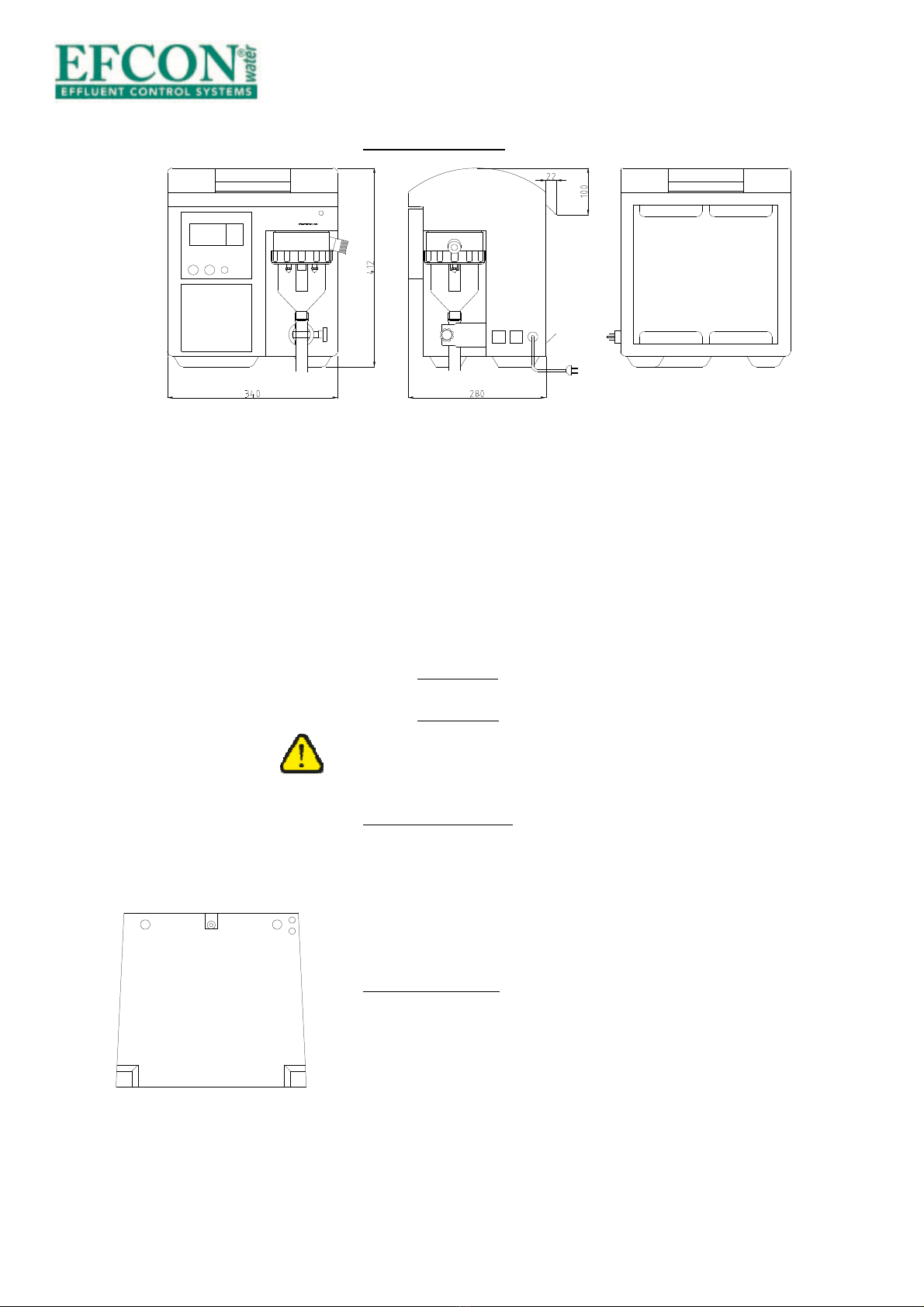
Efcon
®
Carrybox (vacuüm monsternemer)
Elektrisch :
•Voedingsspanning / stroom
•Vermogen
230V AC ±5% / 1 A / 50 Hz
±100 W
Behuizing
•Hoogte
•Breedte
•Diepte
•Gewicht
•Materiaal
•Afsluitplaat
Thermoplastisch Groen draagbaar model
•412 mm± 2%
•340 mm ± 2%
•302 mm ±2%
•± 9 kg
•LLDPE
•Aluminium met ophang sparing
Omgevingscondities
•Protectie klasse
•Omgevingstemperatuur
•Zon instraling
•Zone
•IP 41
•0°C tot +40°C
•Mogelijk, bij voorkeur voorkomen
•Niet in explosiegevaarlijke ruimtes.
2.2 Measurements and parts
Efcon
omy enclosure
) Main switch (left side standard)
B) Sample / suction hose inlet
C) Protect cover of the cool shaft
D) Power supply
E) Mounting brackets
F) Electrics front plate with buttons and display
G) Sample garniture (only for vacuum systems)
H) Distributor engine with bracket
I) Sample container
J) Cooled sample storage compartment
A
B
C
B
D
E
E
F
G
H
I
J
Fig. 2.2a
Installation & User Manual - Sampling Systems
Version 140618 UK
Page 8
R
Efcon
Carry-Box Enclosure
) Handle
B) Operating panel
C) Vacuum chamber
D) Pincher
E) Splash board
F) Connectors
G) Power supply
H) Suspension bracket
2.3 Installation
2.3.1 Mechanical
First determine where the sampler must be placed (in case of an ILS
system) before installing the enclosure. This way you can check if the
sample hose (from sampler to enclosure) has a gradual slope.
Efcon
omy enclosure
Place the enclosure on a firm horizontal (water-levelled) ground and fix
the enclosure with the two supplied SS mounting brackets, bolts and
plugs. BE CAREFULL! Don’t turn the M6 bolt too tight in the enclosure.
Beneath the enclosure a condensate drain outlet is fitted. The outlet has a
push-in fitting for 8 mm tubing. See fig. 2.3a.
Carrybox enclosure
This enclosure is only available for vacuum and peristaltic samplers.
Mount ±300 mm DIN-rail horizontal to the wall on which the enclosure is
placed. Make sure there is sufficient height for an gradual, siphons free
and nod free sample drain to the container.
A
D
D
A
B
C
E
F
F
H
Fig. 2.3a
Fig. 2.2b
G

Installation & User Manual - Sampling Systems
Version 140618 UK
Page 9
2.3.2 Electric:
Work as followed when installing the enclosure:
•Remove the protection cover (B in fig.2.3b) from the cool shaft by
loosening the four bolts which hold the cover. If necessary remove
the connector and earth cable from the fan on the cover to create
more working space. Loosen the two grip nuts from the electro
front plate ( in fig.2.3b). Unplug the connectors to remove the
plate from the enclosure
•Pull the connection cable through the cable tubes which run
through the enclosure ( in fig.2.3c).
•Pull the cable through the cable glands (B in fig.2.3c) on the
separation plate between the cool shaft and electronic
compartment. Strip the cables long enough to reach the terminal.
Terminal connections
Power supply
Connect the power supply cable (230V C/50Hz) to contacts 1 (live), 2
(null) and 3 (ground) of the terminal (see sticker in fig.2.3d).
Pulse Input
Connect the potential free pulse / batch contact to contacts 4 and 5.
(pulse input) for pulse registration and pulse proportional sampling. Be
aware: keep the pulse input frequency <1 Hz. Use a pulse length of ±100
msec.
When using the pulse input for batch control sampling, the pulse counter
in the display counts every batch contact.
Digital Input 1 & Digital Input 2
Connect a potential free contact to contact 4 & 6 (DI1) and/or
4 & 7 (DI2), check §3.5.6 to configure the inputs.
Analogue Input (current)
Connect the 4—20m flow signal cable to terminals 8 (+) & 9 (-). Check
§3.5.5 to configure the analogue input.
Digital output 1 (2= optional)
Terminals 10 and 11 are used for the programmable digital output 1,
The relay output is normally open. Terminals 10 & 12 are used for digital
output 2. Check §3.5.6 to configure the digital output.
A
B
A
Fig. 2.3b
Fig. 2.3c
Fig. 2.3d

Installation & User Manual - Sampling Systems
Version 140618 UK
Page 10
In-/output Connectors (optional)
Optional for
Efcon
systems are connectors on the side. Connect the pins
of the connectors according fig. 2.3e. Place the cable inlet downwards to
prevent moisture inside the connector.
230V C Power supply in (male connector)
•Pin 1 = L 230V C 50Hz
•Pin 2 = N 230V C 50Hz
•Pin PE = GND
24VDC Power supply in (female connector)
•Pin 1 = +24V DC
•Pin 2 = 0V DC (gnd)
Flow Input (female connector)
•Pin 1 = + 4-20m
•Pin 2 = - 4-20m
•Pin 3 = potential free contact
•PE = potential free contact
Distributor Output (female connector)
•Pin 1= + 24V DC
•Pin 2 0 V (Gnd)
Sampler Output (female connector)
•Pin 1 = +24VDC sampler
•Pin 2 = -24VDC sampler
•Pin 3 = sampler response signal (24VDC pulse) optional
Digital Outputs (optional), (male connector)
•Pin 1 = Digital output 1 (potential free contact)
•Pin 2 = Digital output 2 (potential free contact)
•Pin 3 = Common digital output1&2
230V C Power supply out (female connector)
•Pin 1 = L 230V C 50Hz
•Pin 2 = N 230V C 50Hz
•Pin PE = GND
Fig.2.3e
Fig. 2.3e

Installation & User Manual - Sampling Systems
Version 140618 UK
Page 11
2.4 Maintenance
Be aware! Switch off power supply before maintenance or revision.
Remove compressed air couplings and remove pressure and medium
from wastewater piping.
Maintenance and reparations should be done by qualified personnel.
Avoid direct contact with wastewater. Wear protective gloves during use,
maintenance and reparations.
The maintenance frequency depends on wastewater characteristics. Clean
(or replace if necessary) all parts which come in contact with the sampled
medium regular.
Check if the cool shaft of the cooler is clean / not clogged by dust.
Cleaning the enclosure can be done with a moist cloth, but avoid all
electrical parts.
Check annually if the screws of all the electronic connection are tightened.
2.5 Trouble shooting
Problem Diagnose Solution
Cooler freezes the
containers
Wrong settings controller
Door not closed
Door “leaks” air
24VDC circuit out of
range
Check setting (§3.5.7)
Close door, check rubber
seal of the door with a
flash light.
djust the pot. meter on
the power supply to
24,00 VDC ±0,10 VDC.
Cooler doesn’t cool Wrong settings controller
Fan inside the protection
cover doesn’t work
Check settings (§3.5.7)
Check / replace fan
Distributor does not turn
(properly)
Wrong distributor
settings
Check settings (§3.5.7)
Hex. bolt on the
distributor engine is loose
Fasten bolt
Silicon hose doesn’t turn
free in rotation
Shorten silicone hose
Installation & User Manual - Sampling Systems
Version 140618 UK
Page 12
3 Program settings
Be aware! Incorrect settings may lead to defect hardware.
Adjusting parameter settings should be done by qualified personnel.
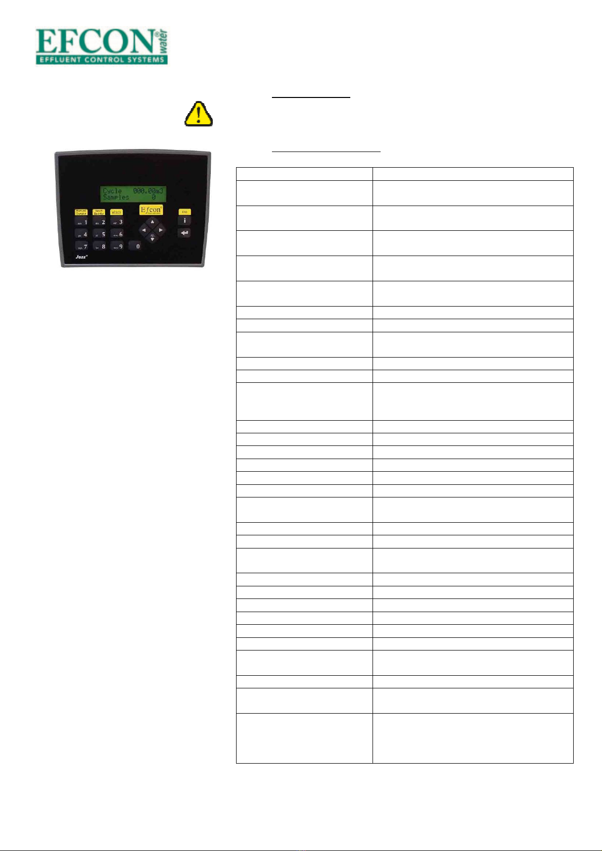
3.1 Technical specifications
Setting Range
Display 2 lines 16 characters, 16 keys, Totalizer
3000000,0 m
3
max (autom. resets)
I/O hardware 8 digital inputs, 4 analogue inputs, 11 relay
outputs
Basic operation Manual sample button, Next container button,
Reset button
Inputs Pulse input, Current flow input (4-20m ),
2x digital inputs (free config.)
Outputs 1x 24VDC relay output (free config.)
(2x optional)
Sample principle ILS / Vacuum / Peristaltic
Sample program Volume / Time / Batch
Sample interval 0,1- 2500,0 m
3
/ sample
2- 250 minutes / sample
Max error samples 0-999
Sample Volume 1-9999 ml
Vacuum settings
Peristaltic
Purge time 1-99 sec
Max suction time 1-99 sec
Dose time 1-99 sec
ILS settings ctivation time 1-99 sec
Turn time 00:00 - 23:59
Select day (MTWTFSS)
Turn Interval 00:00:00 - 99:59:59 (HH:MM:SS)
Container config. 1-24 containers, volume 0,01-99,99 l
Overflow protection Off, move next container, stop sampling
Program settings Start program according date & time (0=Off)
Stop program according date & time (0=Off)
Stop after xx containers 0-99 (0= Off)
Password Yes, (1-9999)
Date & time Changeable (no automatic summer / winter
time)
Cool unit set points On = 1-99°C, Off = 1-99°C
Defrost cycle Interval 1-99 hours, duration 1-99 minutes
Offset -99 - 99 °C
Defrost time 0-99 hours (0= continue cooling)
Eco cool On/Off
Flow signal Pulse / current / pulse + current
Pulse input
0,1 – 1000,0 m
3
Pulse unit: m3 / l / p
Current 20m = 1,0 – 360,0 m
3
/h
Input Options
(2 inputs)
Program on/off, Start program, Stop program,
take sample, next container, start cool unit.
Output Options (1 output)
(2
nd
output optional)
General alarm, sample alarm, sampling active,
sample ok, high temperature, sample error,
1m3 Pulse, 0,1 m3 pulse, 0,01 m3 pulse,
Containers full

Installation & User Manual - Sampling Systems
Version 140618 UK
Page 13
3.2 Operation explanation
3.2.1 Sampling
Sampling system can take samples on three different principles:
•Manual sample, by pushing a button on the operation panel.
•utomatic sample, as programmed:
-Time proportional sampling
-Volume proportional sampling(by pulse input or current input)
-Batch sampling (start time prop.sampling when the pulse
input is active).
•utomatic sample on programmed start- and stop date.
3.2.2 Container distributor system (optional)
The distributor ensures a proper sample distribution across different
sample containers.
Systems with multiple sample containers are equipped with a direct
distributor. The distributor positions the sample hose from the sampler
(clockwise) above the container. This operates automatically (by program)
of manually (by push button). The distributor is programmable to turn on:
•Fixed time (example: set on 10:00) & selected days.
•Time interval (example every 2 hours), time interval starts after
programmed fixed time.
•fter a number of taken samples, dependable on sample and
container volume (overflow protection).*
* When the distributor turns the cycle totalizer & sample counter
are reset. These values are stored in the jazz controller.
3.2.3 Cycle data (optional)
The display totalizes the cycle’s m
3
and taken samples. These values reset
when a new cycle is started (the distributor rotates to the next container).
The values are stored with the average temperature and date & time. The
controller stores up to 24 cycles.
3.2.4 Alarm function (optional for In Line Samplers)
fter multiple sample failures or power failure the alarm output relay of
the sampling system closes.
When a sample cycle is not completed the CPU registers an error sample.
fter a set number of error samples (default = 3) the sampler stops taking
automatic samples and switches to alarm condition. The alarm is
perceptible on 2 ways:
• programmed output relays switches.
•Display describes current alarm status.

Installation & User Manual - Sampling Systems
Version 140618 UK
Page 14
Push the Reset button on the controller to reset the alarm. fter
resetting, the system will sample according program. lso when power
failure occurs, the alarm contact closes.
3.2.5 Sampling on programmed periods
By activating this setting it is possible to start and stop automatic sampling
on a programmed date and time. This way the system can be
programmed (§3.5.11) to take samples only.
3.2.6 Stop sampling after xx containers
When activated the sampler stops sampling after a programmed number
of containers. By pushing Reset, the system samples further until the
same number of samples are taken §3.5.12.
3.3 Manual operation
The sampling system can be manually operated by 3 numeric keys on the
sampler controller. But only when the menu is not entered.
•(1) Manual Sample, push to take an manual sample.
•(2) Next Bottle, push to sample in the next container
(The distributor will wait 3 seconds).
•(3) Reset alarm, if the alarm is activated (too many error
samples), push this button to reset an alarm.
3.4 Display & cycle data read out
The display changes every 5 seconds between:
1
st
row: Totalizer in m
3
, this totalizer doesn’t reset.
2
nd
row: Program status, this shows the status of the program.
1
st
row: Cycle totalizer in m
3
, resets when turning to next container.
2
nd
row: Samples taken this cycle, also resets when turning.
1
st
row: Time & current flow (in m
3
/h).
2
nd
row: Date & current temperature (in °C).
Access stored cycle data:
When one of the above displays is active, press ▼to read the previous
cycle data, press ▼ again to read the cycle before that, press ▼ again
etc..
1
st
row: Data cycle number, end date & end time of the cycle
2
nd
row: Total m3 counted this cycle
Press ►to check the number of taken samples & average temperature
1
st
row: Data cycle number, number of taken samples this cycle
2
nd
row: verage temperature during this cycle
Total 00000,00m3
Program stopped
Cycle 00000,00m3
Samples 236
16:55 0,0m3/h
10/07 3°C
#1 31.12 08:00h
> 1000,00m3
#1 100 S
< 4°C

Installation & User Manual - Sampling Systems
Version 140618 UK
Page 15
3.5 Changing Sampler settings
To change settings it is necessary to enter the program of the Jazz
controller. The controller is password protected (default 5555), this
password can be changed or canceled.
3.5.1 Changing date/time
•Press Enter to enter the password
•Enter 5555 and press Enter
•Select Program settings with 2x ►
•Press Enter to select
•Press 3x▼and press Enter
•Enter the date with numeric keys and press enter
•Enter the time with numeric keys and press enter
•Press 2x ESC to go back to the total display
3.5.2 Changing Settings
See the attached menu diagram ( ppendix I) for a quick view of all the
parameters.
To change settings:
•Press Enter to enter the menu,
•Enter password (default 5555) & press Enter
•Select the submenu with ► or ◄ and press Enter
•Scroll with ▼and ▲ trough the parameters
•Press Enter (◄ or ► with parameters with ← or → signs) to
change the parameter value.
•Use numeric keys to enter a value & press Enter to store
Submenu
Parameters
Sample settings
Sample by, Sample Interval, Error Sample Max,
Sample Volume, Purge time (VS/PS), Max.
suction time (VS/PS), Dose (VS/PS), activation
time (ILS)
Distributor settings
Turn Time, Turn Day, Turn Interval, Containe
r
Config., Overflow protection
Program settings
Start date/t
ime, Stop date/time, Stop fter xx full
containers, Change date/time, Change password
Input
/output settings
Flowsignal, Pulse Value, Current 20m value,
Input 1&2 config, Output 1&2 config, Com.
settings(optional)
Cool Unit Settings
Set
points Cool unit, Defrost cycle, Temperature
offset, Defrost Time, Eco Cool settings.

Installation & User Manual - Sampling Systems
Version 140618 UK
Page 16
3.5.3 Changing Sample Settings
Select submenu Sample Settings and press Enter.
Select from the following parameters. Press Enter to change its value.
Parameter
Description
Sample by
Select with
◄
or
►
the following:
Volume Interval: sample every xxx,xx m
3
by flow
signal (pulse or current).
Time Interval: sample every xx minutes.
Batch: sample every xx minutes when the pulse
input is activated.
Sample interval
Enter the value of the desired interval
.
Error sample max
Enter the
max
.
number
of consecutive error
samples to trip the sample alarm.
Sample volume
Enter the sample volume
.
Purge
-
, Max suction
-
,
Dose- (VS only) &
ctivation Time (ILS
only)
Purge time:
time to clean
the suction tube
.
Max suction time: maximum time to reach the
level pins. Dose time: time to dose the sample.
ctivation time: time to activate the ILS sampler.
3.5.4 Changing Distributor Settings
Select submenu Distributor Settings and press Enter.
Select from the following parameters. Press Enter to change its value.
Parameter
Description
Turn Tim
e
Enter the
clock
time the distributor needs to
change the sample outlet to the next container.
Turn Da
il
y
Select the days the distributor needs to turn,
Everyday, Skip Sunday, or Off(don’t turn on the
Turn time)
Turn Interval
Enter the desired time int
er
val for the distributor
to turn (0=off).
Container c
onfig.
Enter the number of containers & container
volume.
Overflow protect.
Select
what action to take when the container
starts to overflow: Off (continue program), Next
container, Stop sampling (& restart when the
turn time is reached).

Installation & User Manual - Sampling Systems
Version 140618 UK
Page 17
3.5.5 Changing Program Settings
Select submenu Program Settings and press Enter.
Select from the following parameters. Press Enter to change its value.
Parameter
Description
Start Date-time Enter date & time to start sampling (00-00 = off).
Stop Date-time Enter date & time to stop sampling (00-00 = off).
Stop after full containers Enter desired number of container to be filled, the
sampler then stop sampling & restarts when reset is
pushed.
Date time. Enter time & date. Change it when needed.
Password Enter a number from 1-9999 to change the password.
3.5.6 Changing Input / Output Settings
Select submenu Input / Output Settings and press Enter.
Select from the following parameters. Press Enter to change its value.
Parameter
Description
Flow signal Select with ◄ or ► to totalize the desired flow signal.
Pulse = totalize contact (>50 ms) on the pulse input.
Current = totalize a 4-20m flow signal.
Pulse + Current = totalize contact on the pulse input,
current is only to display.
Pulse input value Select the pulse unit= 0=none, 1=m3, 2= l, 3=p
lso assign a value to the pulse contact, 0,1 -1000,0
(0,1 for current flow signal).
Current Value Enter the 20m value of the current signal
2600,0m
3
/h max.
Input 1 config.
Input 2 config.
Select with ◄ or ► to configure the inputs.
Choose from the following functions:
Start/Stop PRG, Start Program, Stop program
Take Sample, Next container, Start Cool unit,
Not in Use.
Output 1 config.
Output 2 config.
Select with ◄ or ► to config. the outputs.
Choose from the following functions:
General larm, Sample larm, Temperature High,
Sampling ctive, Sample OK, Error sample, 1 m
3
pulse,
0,1 m
3
pulse, containers full.
Communication settings ID# = Unit ID number, sign a unique network ID
number, Pari= Parity (0=even, 1=odd, 2=none),
Baudrate (legal baudrates=300, 600, 1200,2400, 4800,
9600)
3.5.7 Changing Cool unit Settings
Select submenu Cool Unit Settings and press Enter.
Select from the following parameters. Press Enter to change its value.
Parameter
De
scription
Cool Unit On/Off On and off set points cool unit.
Defrost cycle Fill in the desired interval (F) in hours and how many
minutes the Cool Unit needs to defrost (t).
Temperature. offset Temperature offset, to correct the temperature
measured inside the cabinet.
Defrost Time Fill in the desired time (in hours) to stop the cool unit.
Set to 0 hours to activate the Cool Unit again.
ECO cool Not available.

Installation & User Manual - Sampling Systems
Version 140618 UK
Page 18
4 Vacuum sampler
4.1 Technical Specifications
Vacuum
sampler conform ISO 5667
-
2&10
and
NEN 6600
-
1
Sample principle
• Max. suction height
• Minimal suction speed
• ir pump
• Pincher
• Sample volume
• Repeatability
• Dose accuracy
• Medium temperature
• Max. sample frequency
• Diameter suction hose
• Coupling suction hose
• Material vacuum chamber
• Sample settings
Principle Vacuum suction
• 4 meter (optional 6)
• 0,5 m/sec
• 24 VDC bi - directional ± 2800 rpm
• 24 VDC bi - directional ± 30 Nm with Current
Limiter.
• 20 ml tot 250 ml adjustable, 50 ml prefab
• 2% (at 50 ml and more)
• 4% (at 50 ml and more)
• max 50°C (higher on request)
• 1 sample / 2 minutes (software blocked)
• 16 mm (minimal 12 mm) inside
• 3/4”
• Polycarbonate
• djustable purge, suction time out, dose
time
4.2 Parts
Hardware of the vacuum sampler is located in the sample storage
compartment, with exception of the air pump.
) Coupling suction hose
B) Vacuum head
C) PP glass holder
D) Vacuum glass
E) Contact pins
F) Sample volume hose
G) Pincher
H) Pincher nut / bolt
I) Sample drain hose
A
A
B
C
F
E
D
G
G
H
I
Fig. 4.2a

Installation & User Manual - Sampling Systems
Version 140618 UK
Page 19
4.3 Operation principle
The sampling cycle from a vacuum sampler:
•CLOSING PINCHER: the pincher squeezes the silicone hose air
tight.
•PURGE: the air pump starts and generates pressure in the sample
chamber. From the end (inlet) of the suction hose air bubbles will
escape. Which is a sign the ‘old wastewater’ has left the suction
hose.
•SUCTION: the air pump changes rotation and a vacuum is created
inside the sample chamber. Wastewater will be sucked up
through the suction hose until it reaches the level pins. If the pins
aren’t reached within a programmed time (default 30 sec.) the
sampling system will count an error sample and will wait until the
next sample must be taken. fter (default setting 3) error samples
the sampling system will switch in alarm.
•DOSE: The level switch changes the rotation direction of the
pump. This creates pressure in the sample chamber and will blow
the excess volume back through the suction hose. fter a short
period (default 10 sec.) air bubbles escape from the end (inlet) of
the suction hose.
•PINCHER OPEN: the pincher opens and the sample will drop to the
container. fter several seconds the air pump stops and the cycle
is complete. The sampler waits a minimum of 1 minute* (due to
cooling period air pump) till the next automatic sample is taken.
* ll vacuum samplers have a 1 minute pause time between two
taken samples to give the air pump time to rest / cool.
4.4 Installation instructions
Follow the following procedures during installation
•Connect the suction hose to the supplied suction hose coupling.
Feed the hose through the inlet and fasten the gland air tight.
•Mount the end (inlet) of the suction hose on a fixed
representative turbulent point to sample homogeneous
wastewater. Ensure the suction hose is always emerged in the
wastewater / medium.
Fig. 4.4a
Fig. 4.3a

Installation & User Manual - Sampling Systems
Version 140618 UK
Page 20
Keep in mind
•Maximum suction height: 4 meter.
•Maximum suction length: 20 meter.
•void siphons in the suction hose.
•Mount the end (inlet) from the suction hose always downward
and on a lower point than the sample chamber.
4.5 Changing sample volume
With vacuum systems the sample volume is adjustable by the length of
the silicon hose (3 in Fig. 4.5a) inside the vacuum chamber (4). The longer
the hose the smaller the sample volume. Standard sample volume is ± 50
cc. Follow the following procedures to change the sample volume.
• Disconnect power supply.
• Carefully loosen the PP glass holder (2) counter clockwise until the
glass (4) is loose from the vacuum head.
• If necessary remove the white bolt from the pincher to create
more working space.
• Determine the length of the silicon hose (3) (lengthen or shorten).
• Reassemble the parts and connect power supply.
4.6 Maintenance Vacuum samplers
Be aware! Remove power supply, compressed air supply and medium
pressure before maintenance or reparations.
Maintenance and reparations should be done by qualified personnel.
Avoid direct contact with wastewater / medium. Wear protective gloves
during use, maintenance and reparations of the sampler.
Be aware! When removing the sample drain hose from the pincher, the
danger of fingers entering the pincher occurs. This can cause serious
injuries.
Points of attention Vacuum samplers
-Clean the inside of the vacuum chamber.
-Check if the silicone sample hose is intact, replace if necessary.
-Check regularly if the suction hose is clean and intact, replace if
necessary.
-Regularly check the air pump capacity.
-Check if the power supply is 24 ± 0,1VDC.
Afb. 2.5 “Correcte installatie”
Fig. 4.5a
Fig. 4.4b
Table of contents


